Week 9 - Project 1 - Door Applique Design with Engineering Features
DRAFT ANALYSIS OF OF DOOR APPLIQUE
Objectives:
To create TOOLING AXIS, CLASS A, CLASS B & CLASS C surface for DOOR APPLIQUE.
To add thickness to DOOR APPLIQUE & SUPPORT FACE.
To design LOCATORS & HEAT STAKES of DOOR APPLIQUE & add thickness to it.
To perform draft analysis on final component of DOOR APPLIQUE part model.
Creation of DOOR APPLIQUE:
1) Steps to create Class A surface:-
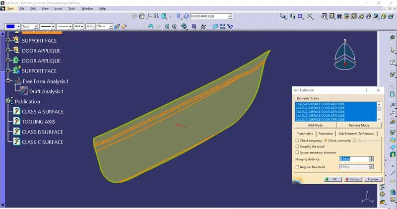
First, create Class A surface using JOIN command to connect different surfaces given in part file. Here merging distance is given 0.1 mm. Rename it as Class A surface.
Publish it using PUBLICATION.
2) Steps to create Tooling Axis:-
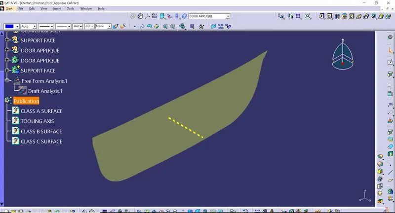
Select Class A surface and create a center point on it and place axis system on it. Use this point to create line in Z direction. Rename it as TOOLING AXIS.
Publish this TOOLING AXIS using PUBLICATION.
3) Steps to create Class B surface:-
Here Class B surface must be above Class A surface to create solid part of required thickness of 2.5 mm.
Extract and Untrim 3 surfaces as shown in figure.
Extrapolate and Trim them together as required.
Apply edge fillet of [15.5 (measured from Class A surface) - 2.5 (part thickness)] = 13 mm as shown in figure.
Rename this fillet as Class B surface.
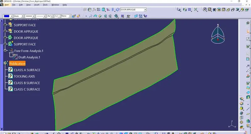
Publish this Class B surface using PUBLICATION.
4) Steps to create Class C surface:-
EXTRACT boundary from Class A surface using MULTIPLE EXTRACT with no propagation.
Now, use CURVE SMOOTH option to smooth out every curve extracted from Class A surface.
Apply SWEEP on the CURVE SMOOTH with draft direction option.
Here use CURVE SMOOTH as guiding curve and TOOLING AXIS as draft direction. Apply 3° draft and length should be about 15 mm for FINAL TRIM.
For corners, EXTRACT boundary separately.
Use SWEEP with draft direction as given in above steps.
JOIN surfaces with merging distance of 0.001 mm except corners.
EXTRAPOLATE surfaces around corners and TRIM them together with this JOIN.
Rename & Publish this TRIM as Class C surface using PUBLICATION.
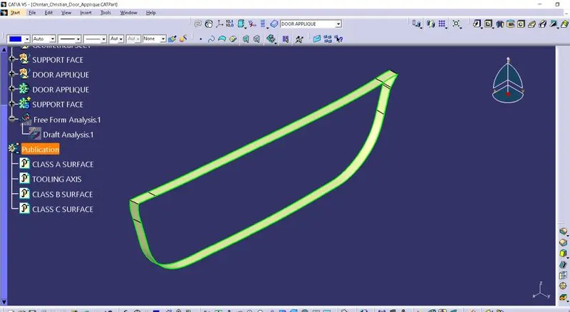
5) Steps to create DOOR APPLIQUE PART:-
Connect Class A and Class C surface using JOIN command.
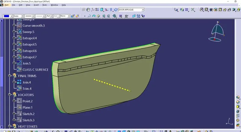
Now, TRIM this with Class B surface.
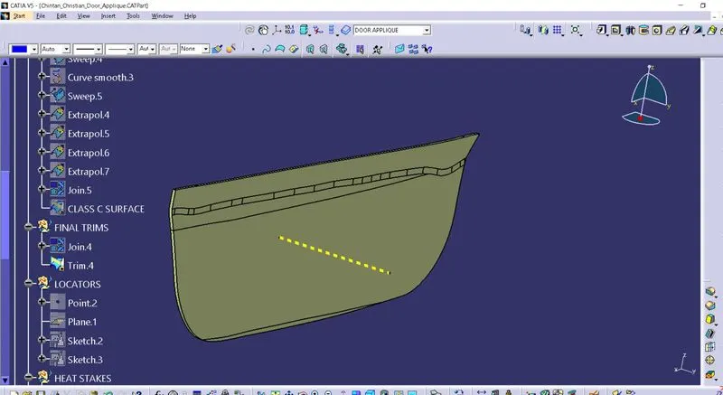
Check this FINAL TRIM for gaps using BOUNDARY command.
When there is no gaps between surfaces, use CLOSE SURFACE to create a solid body from surface.
In this way, DOOR APPLIQUE is created.
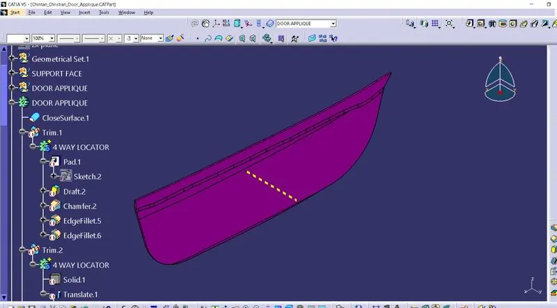
Creation of SUPPORT FACE:
First, create Class A surface using JOIN command by attaching 2 surfaces. Here merging distance is given 0.1 mm. Rename it as Class A surface.
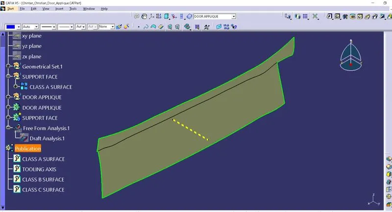
Add thickness to this Class A surface about 2.5 mm.
This will be our SUPPORT FACE.
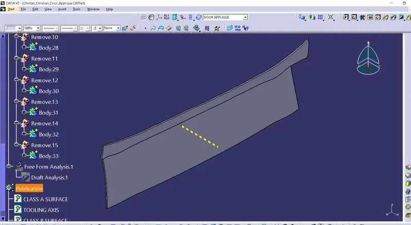
3 - 2 - 1 PRINCIPLE: This principle is used for locating the job. Every object have 12 degrees of freedom - translational as well as rotational movement along X,Y & Z direction. When part is needed to be machined or welded, operator needs to think about how to stop unnecessary movements of an object and to setup object in required direction of motion.
Heat Staking: It is an assembly method which uses controlled melting and reforming of a plastic stud or boss to capture or lock another plastic or metal component of an assembly in place.
Locators: These are supporting parts, which are required to fix position of parts in assembly. Here 4 way locator and 2 way locator is used.
Creation of LOCATORS & HEAT STAKES on DOOR APPLIQUE:
Here shape of DOOR APPLIQUE part is like triangle. So one can place 3 locators as described below.
1) LOCATORS:
First, create a center point and a plane parallel to ZX plane.
Create sketch of 4 WAY LOCATOR as shown in figure.
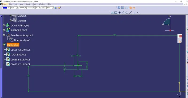
Extrude it about 28 mm towards Class A surface and thicken it about 1.3 mm.
Now, apply 0.5° draft same as RIBS.
Apply chamfer of 3 mm at 45° angle. Apply fillet of 3 mm on these chamfer edges.
Apply 0.3 mm fillet on other edges.
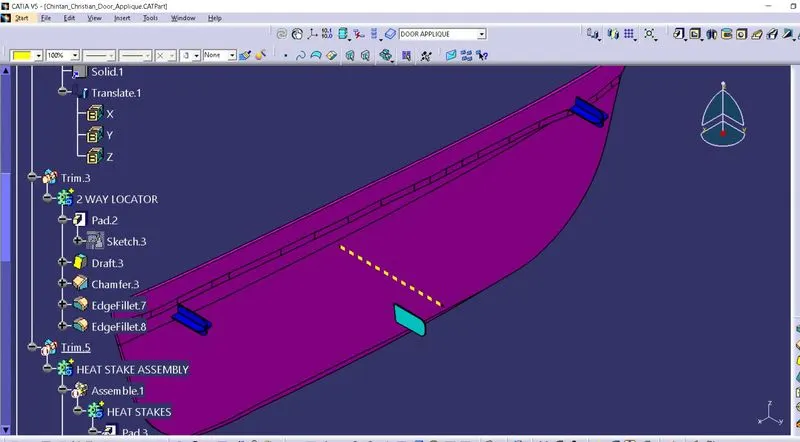
Now, use PASTE SPECIAL and copy paste this locator on DOOR APPLIQUE.
TRANSLATE it as shown in figure.
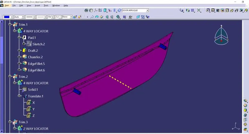
Same way create a 2 WAY LOCATOR on DOOR APPLIQUE.
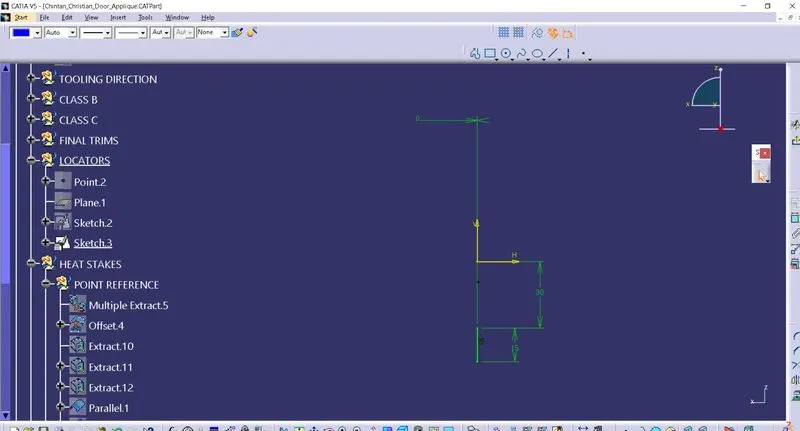
Apply chamfer of 3 mm at 45° angle and fillet it about 3 mm. Apply 0.3 mm fillet on outer edges.
TRIM these 3 locators with DOOR APPLIQUE body.
2) HEAT STAKES:
Extract boundaries from Class A surface using MULTIPLE EXTRACT.
Extract top surface from Class A surface.
Now, use PARALLEL CURVE to offset this Multiple curves.
Create points at equidistance on top straight curve and bottom curve.
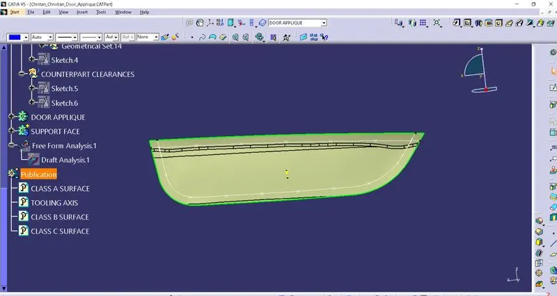
Now, create new sketch on one point with 5 & 7 mm diameter concentric circles.
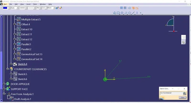
EXTRUDE this sketch upto Class A surface and give draft of 0.5° angle on it.
Now, use PASTE SPECIAL to copy-paste this one HEAT STAKE on different points on parallel curves, which were created in earlier steps. These HEAT STAKES are total 12 in numbers.
Now, ASSEMBLE all HEAT STAKES in a single HEAT STAKE ASSEMBLY body.
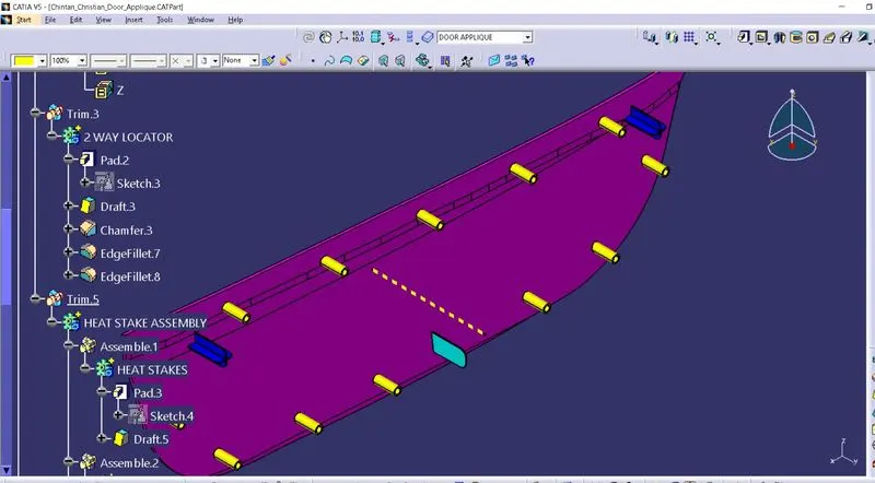
TRIM this assembly body with DOOR APPLIQUE body.
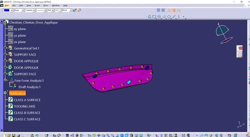
3) COUNTERPART CLEARANCES in SUPPORT FACE:
For LOCATOR HOLE:
0.1 mm gap required along diameter between locator and its hole according to guideline.
Copy sketch of Locator and create 14.9 mm diameter hole in this sketch.
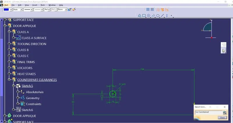
EXTRUDE this sketch upto Class A surface and give it draft of 0.5° angle.
Now, use REMOVE operation to remove this extrude body from support face.
Paste this body of locator hole using PASTE SPECIAL.
TRANSLATE it on position of another 4 WAY LOCATOR as well as 2 WAY LOCATOR.
For HEAT STAKE HOLE:
0.5 mm gap required along diameter between heat stake and its hole according to guideline.
Copy sketch of Locator and create 8 mm diameter hole in this sketch.
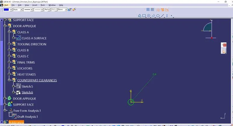
EXTRUDE this sketch upto Class A surface and give it draft of 0.5° angle.
Now, use REMOVE operation to remove this extrude body from support face.
Paste this body of locator hole using PASTE SPECIAL.
TRANSLATE it on position of other 11 points on curves.
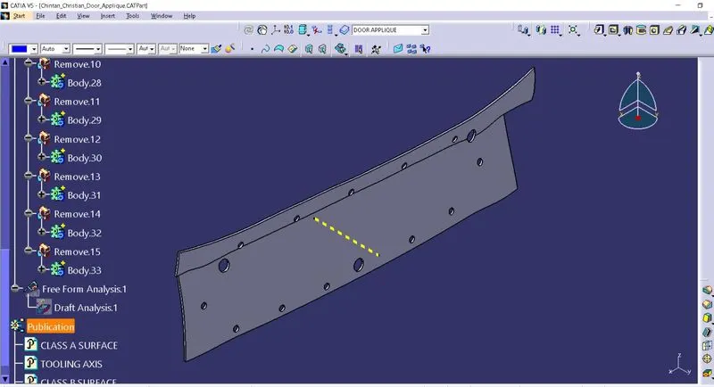
Steps to do draft analysis on DOOR APPLIQUE model:
Go to insert > analysis > feature draft analysis or directly click on Feature draft analysis icon from menu.
First select compass option from pop-up menu to set axis system coincide with tooling axis.
Here change position of TOOLING AXIS by moving compass location and use lock option to fix it to give every surface a proper draft.
Surface model will turn into green colour surface, which shows that draft for model is in limit upto 3 degrees. Here I have given green colour for 0.5 degree draft, light blue for 0 and red colour for negative draft.
Run quick analysis on model and if any draft angle is more than limit, then one can apply new value of it in pop up box.
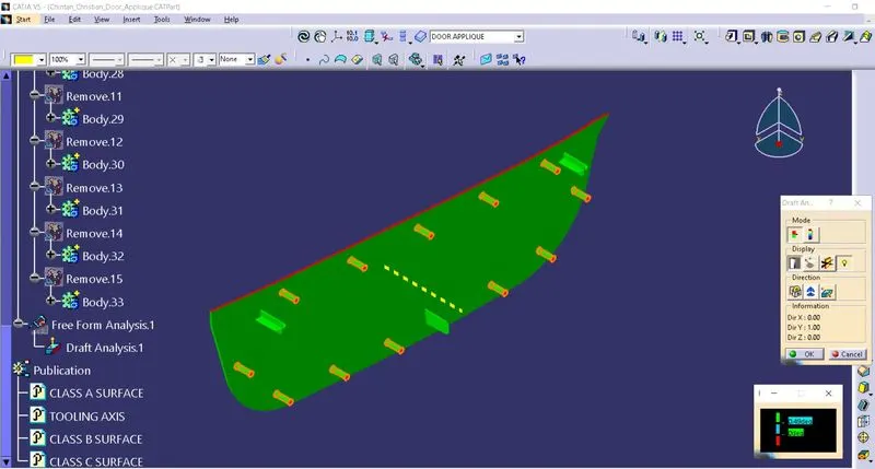
Full analysis shows different draft angles with different colours as shown in figure.
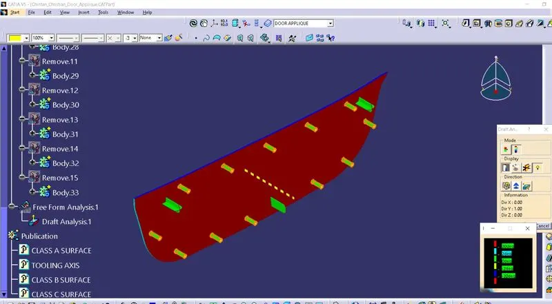
Here is an example of INVERT DRAFT DIRECTION analysis.
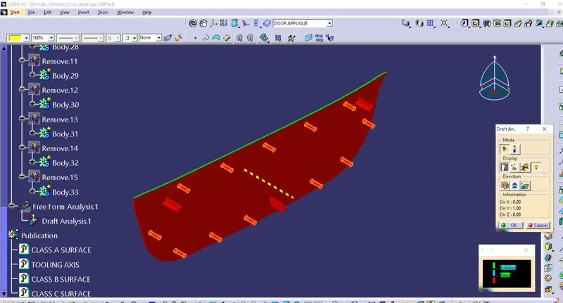
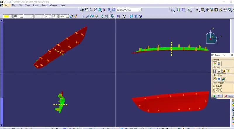
Below image shows the different views of draft analysis of DOOR APPLIQUE model.
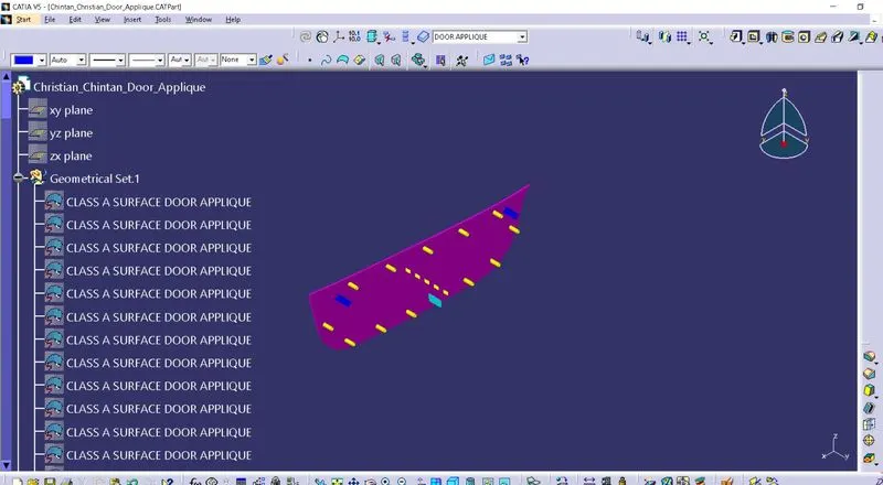
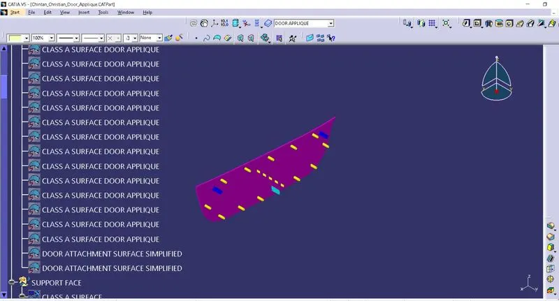
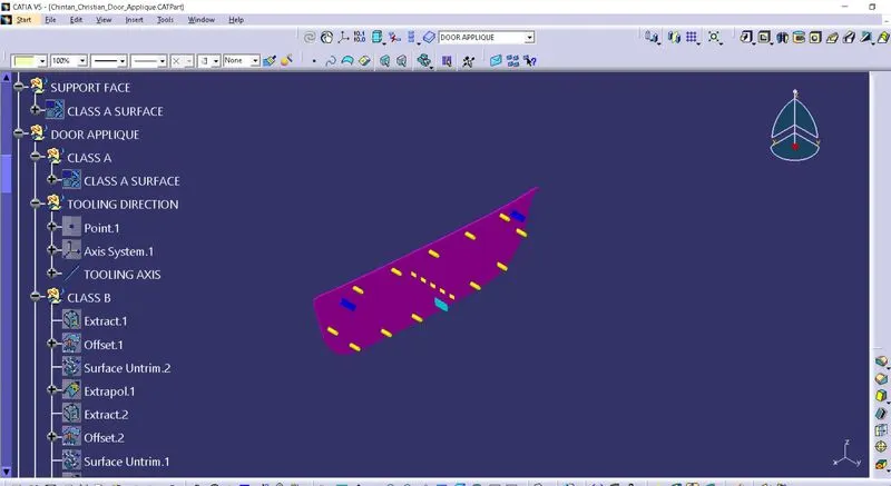
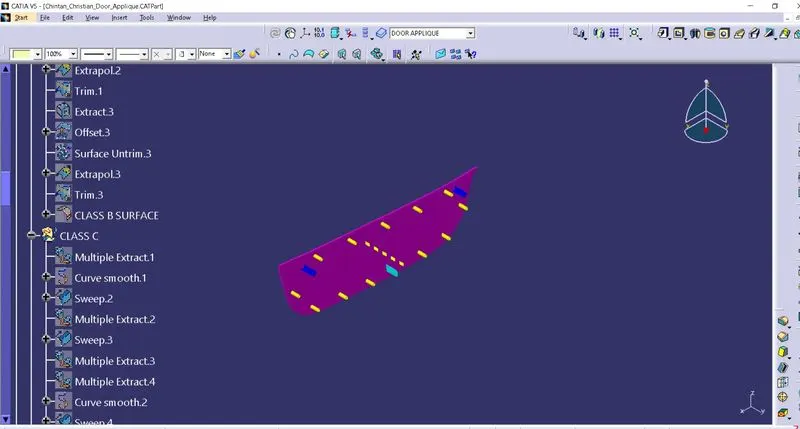
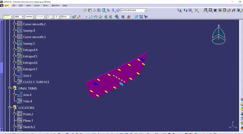
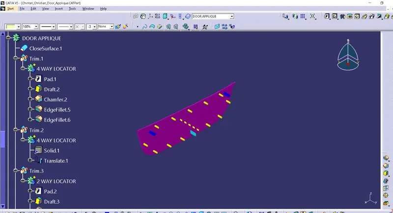
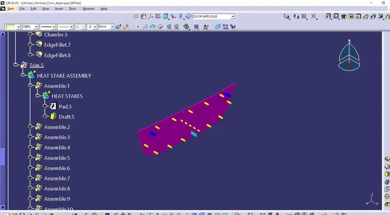
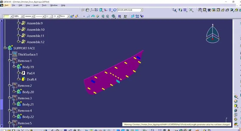
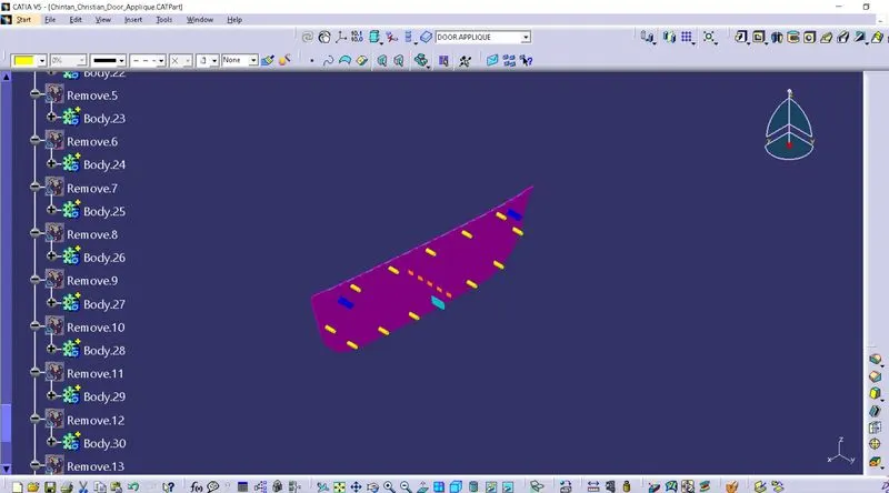
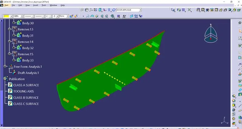
Here are snaps of feature tree of this DOOR APPLIQUE model:

Conclusion:
I have learned about creation of LOCATORS & HEAT STAKES for DOOR APPLIQUE model in this challenge.
Also, I understand the importance of LOCATORS & HEAT STAKES design in terms of industry guidelines.