Photo Realistic Rendering
Modelling and Rendering of American Chopper in Solidworks
Objective:
To create different 3D parts of American Chopper by using 2D sketch.
To assemble different parts of American Chopper and create a full 3D model of it.
To render American Chopper in real environment using Solidworks.
Introduction:
American chopper is a custom build motorcycle, which originated from California in 1950s era.
It gives a stretched appearance because of its especially long forks and modified steering angles. It can be built from scratch or by modifying an original motorcycle.
Characteristics features to know an American chopper by look are lengthy front forks, larger front wheels, long frames, V-Twin engine, custom built dual exhaust pipes and wider rear wheel without any suspension.
In this project report, a complete process of making individual parts is illustrated for creating assembly & rendering of American Chopper with the help of Solidworks and Solidworks Visualise Software. Solidworks is a renowned design software for creating 3D model using 2D sketch. For the rendering of 3D model, one can use Solidworks Visualise for it.
Solidworks: This software is used for creating 3D models, assembly & rendering.
Solidworks Visualise: It is used for high quality render image of 3D model.
Features used:
Extrude: It is used for creating 3D solid from 2D sketch in specified direction (normally at right angle).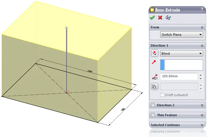
Revolve: To create 3D geometry by revolving 2D sketch about a center axis.
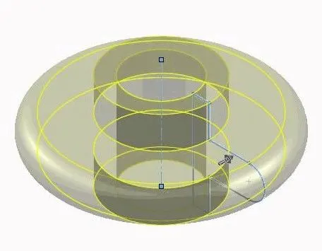
Sweep: To create solid or surface geometry by sweeping 2D sketch across a defined path. Example: Cross-sectional shapes
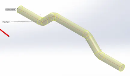
Loft: It is used for creating solid or surface between different cross sections.
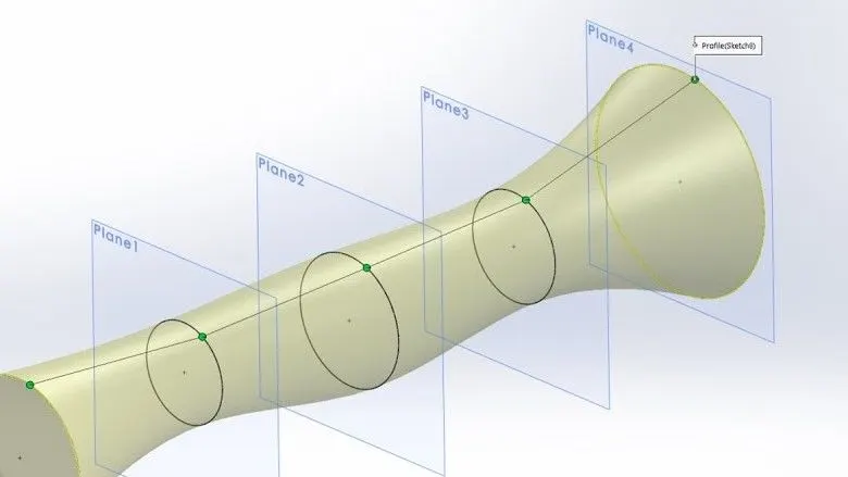
Boundary: To create a profile by following two different profiles in different directions.
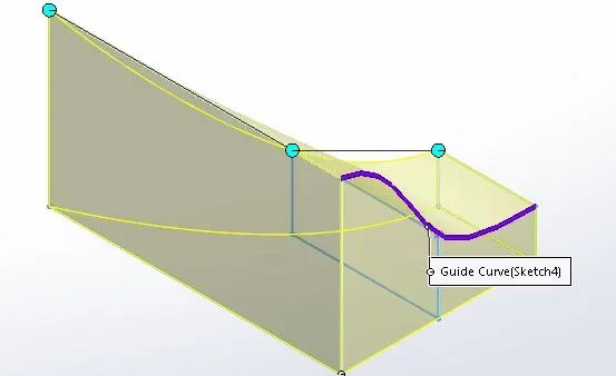
Split: To divide a single face into multiple separate faces by selecting various contours of face.
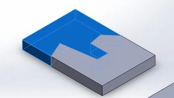
Combine: This tool is used to add/subtract multiple bodies into a single body.
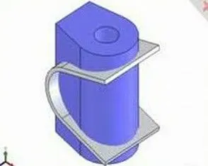
Dome: It is a curved formation over a solid body part.
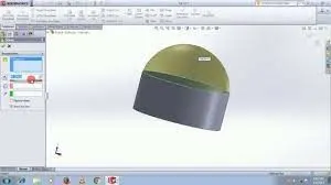
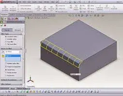
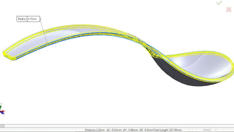
Fillet: It is used for giving radius to edges and corners of object.
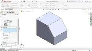
Chamfer: To cut corner into a slope design.
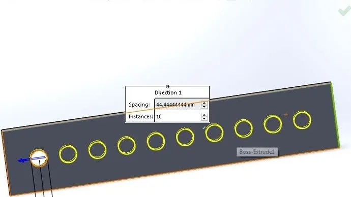
Linear Pattern: To create multiple copies of an object in horizontal or vertical direction.
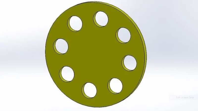
Circular Pattern: To create multiple copies of an object in circular path.
Mirror: To create mirror image of the object.
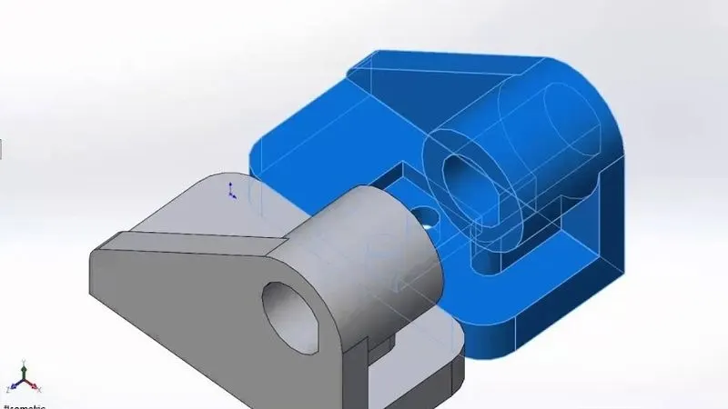
Curve Driven Pattern: To create pattern of an object around given curve.
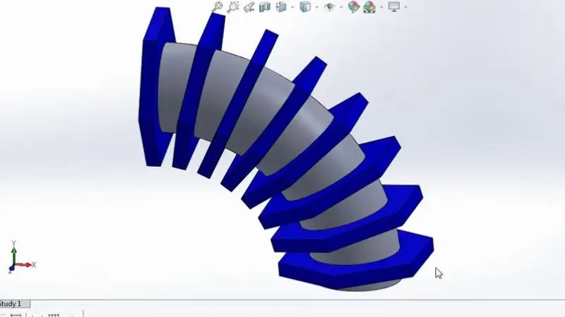
Shell: To create hollow part from solid body.
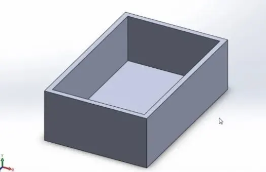
Reference Axis / Plane: To create axis or plane & use it as a reference for given design.
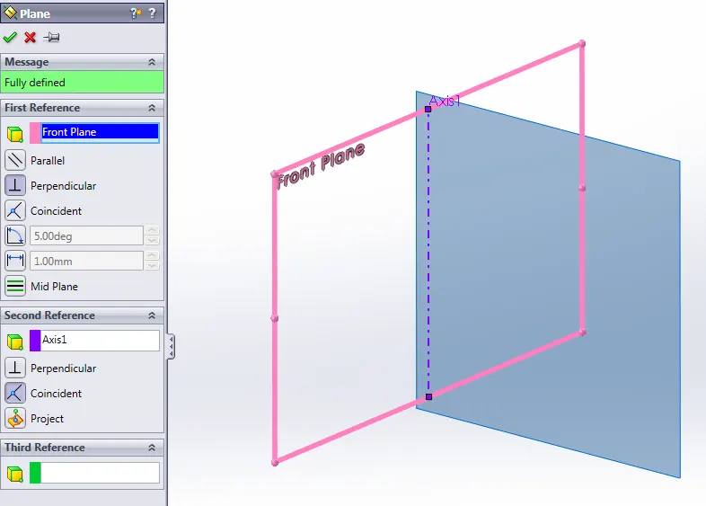
Project Curve: To project curve on different faces of part.
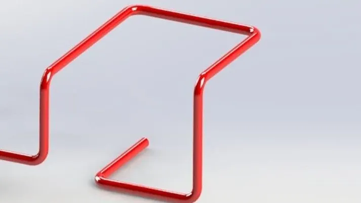
Composite Curve: To join different curves on part.
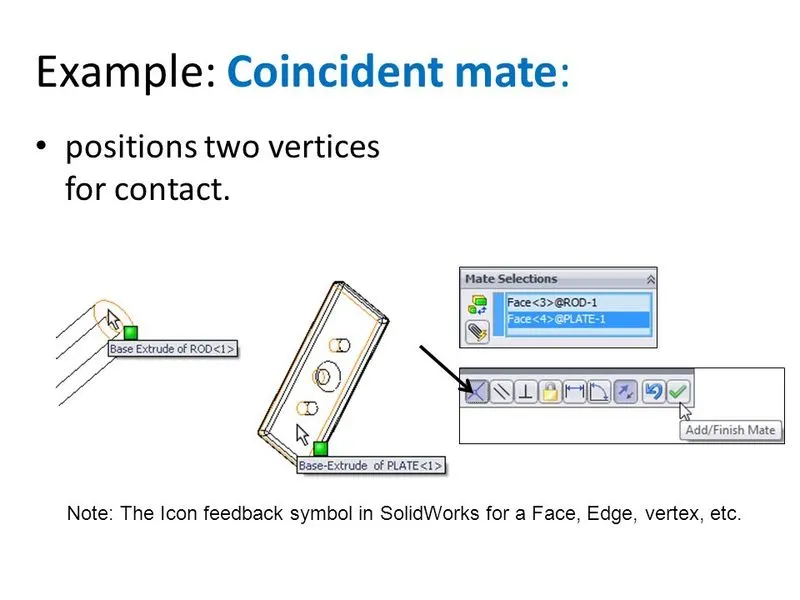
Mate: To give relationships between different parts in assembly. (Examples: coincidence, concentric, offset, etc.)
Component Pattern: To create pattern of different 3D parts. (Examples: Linear / Circular Pattern)
Render Tools: To render and give look to 3D model & assembly in realistic environment just like things in real world.
Design Approach:
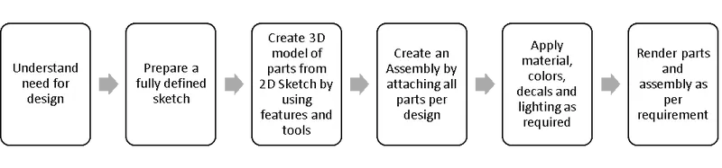
Parts of American Chopper:
This assembly includes different parts as given below:
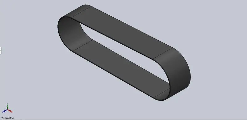
- Transmission Belt:- It is used for transmitting power from engine to gear box.
- Process: First sketch of cross-section of belt is created using two different diameter circles and two lines. Bottom line is horizontal and top line is slant one. Both lines are given tangent relation with these circles. Then this sketch is given certain offset. After completion of sketch of Belt, it is converted into 3D model by using extrude option and then some fillet is applied to it.
- Features used: Extrude, Fillet
- Relation given: Tangent, Horizontal
- Material applied: Matte rubber
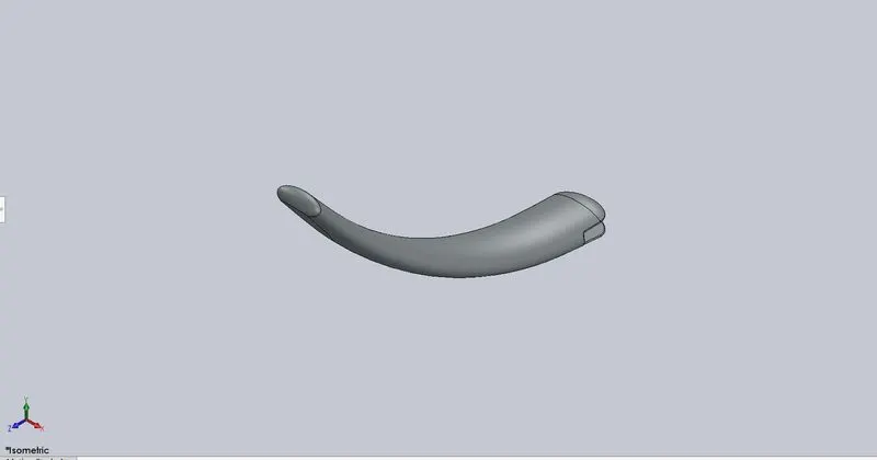
- Kickstand:- It is used for supporting Chopper body when it is at rest position.
- Process: To create body of kickstand, first two different size of ellipse are connected by loft process. Then two ends of it are given dome shape. To connect it with chassis, a portion of material is removed by Extrude-cut & a Boss-extrude is given. Here some fillet is applied for finished edges. In the end of process, a small portion of material is removed by Split option to make it grounded.
- Features used: Loft, Dome, Extrude cut, Extrude, Fillet, Split
- Relation given: Coincident, Horizontal, Vertical
- Material applied: Chromium plate
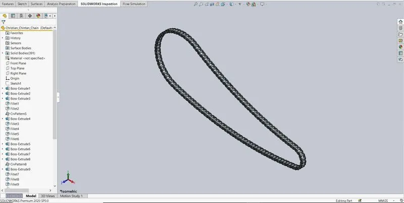
- Chain:- It is used for transmitting power from gearbox to rear wheel via sprocket mounted on wheel & engine.
- Process: First a path for chain is created by drawing a fully defined sketch with two different diameter circles and two different splines. Then a link is generated with use of extrude for two front chain plates and one back plate with 3 pins. Also, some fillet radius is given to these. After creation of link, a curve driven pattern is used for making copies of link along curve for different sections of it. One last back chain plate is created & attached individually to complete one side of chain. In the end, mirror is used to make it as whole part.
- Features used: Extrude, Mirror, Fillet
- Relation given: Tangent, Collinear, Coincident, Vertical
- Material applied: Chromium plate
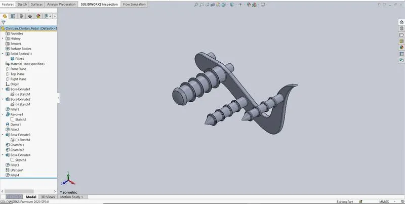
- Pedal:- It is used to give rest to rider’s feet while driving.
- Process: Sketch of Pedal is created by using circles, lines, arc & splines. Then its model is generated using extrude. For foot support, total 5 bosses of different sizes are created using extrude and some rings are created along 3 of these bosses. These rings are created with the help of linear pattern. The biggest boss among these 3 is given large fillet radius with dome at the end of it. The other two bosses are chamfered at their front ends to make cone shape. Last 2 bosses of smaller size on the back side of pedal is used as pins for mounting on chassis. At last, a common fillet radius is given to component as shown in figure.
- Features used: Extrude, Linear pattern, Fillet, Chamfer
- Relation given: Coincident, Tangent, Horizontal, Vertical, Angle
- Material applied: Chromium plate
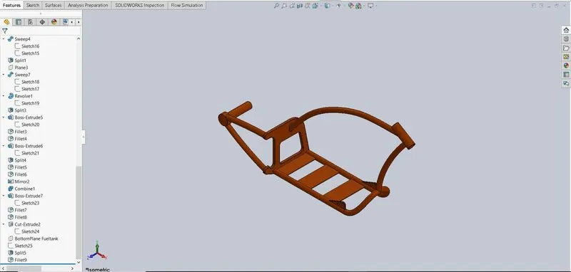
- Chassis:- It acts as framework to support various parts like Engine, Gas tank, Oil tank, Pedal, Front fork, Kick stand.
- Process: First create a half horizontal tubes of chassis. To do that, 4 different curves are drawn & by using composite curve option, a single curve according to blueprint is generated. Then by using, sweep option, a first portion is created and after that mirroring this portion with plane vertical to it, a full horizontal portion is created. Now, backside of chassis, which supports rear wheel, is extruded from 2D sketch. Material is removed from backside with extrude cut & some chamfer and fillet also applied to this portion. Again, 2 sweep tubes are used for making support for rear wheel. At the intersection of these tubes, a boss extrude is created and on its backside, a dome shape is applied. Here 3 base plates are created by extrude along horizontal portion and a portion to connect pedal is also created & mirrored along plane. A pin hole is given for kickstand. Front fork support is created on front side of chassis with the help of sweep tubes and a hollow boss extrude at joint between them. Fillet required is given all over the chassis. A bottom fuel tank plane is also defined. To give unrestricted motion to the chain, a corner part of chassis is chamfered.
- Features used: Sweep, Extrude, Extrude cut, Fillet, Chamfer, Mirror, Combine, Dome
- Relation given: Tangent, Horizontal, Vertical, Concentric, Angle, Coincident
- Material applied: Siena
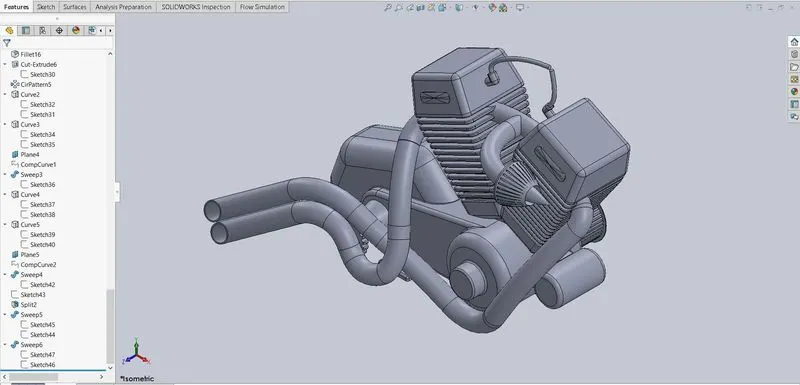
- Engine:- Engine is the most important part because it gives power for running any vehicle. Here multi-cylinder V type engine is used in American Chopper.
- Process: Here engine outer body is created by using extrude and fillet option for different portions and with the help of blueprint. Two boss extrudes are created on side of it for supporting transmission belt. To retain proper grip of belt on these bosses, number of flat teeth are modelled with the help of extrude & circular pattern on the periphery of these. Dome shape and bolt head holes are applied on outer side of these bosses. Required fillet & chamfer is given them also. Here electric motor casing & its mounting plate is joined with engine outer body. Then a single engine cylinder, its head & its outer fins is created by extruding & giving linear pattern to a fully defined sketch of it. Mirror of this cylinder is given at angle to make them V-shape. Required fillet is applied. 4 mounting plates of T-shape is created at bottom of engine. For chain drive mounting at gearbox side, a sprocket is created. After this, a conical air filter with its intake manifold pipe connected with cylinders is modelled according to dimensions. Also two round L shaped spark plugs with cables are created. In last, two custom exhaust pipes are designed with the help of splines, composite curves and their ends are converted into ellipse cross section with the help of split tool.
- Features used: Extrude, Extrude cut, Sweep, Composite curve, Reference plane, Linear & circular pattern, Fillet, Chamfer, Split, Dome
- Relation given: Horizontal, Vertical, Coincident, Concentric, Angle, Tangent
- Material applied: Rubber for Spark plugs, Chromium plate for Engine
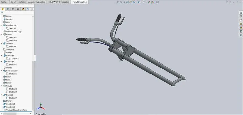
- Front Fork:- It connects front wheel to chassis with triple clamps. It helps rider to turn chopper in desired direction.
- Process: First create half 3D portion of Front fork. In this portion, a single side bar, 2 half triple clamps, a headlight & one side handle bar with brake are included. First create side bar with revolve option. Then create a half triple clamp by using extrude & fillet. Here generate another half clamp by giving linear pattern to original. To create a headlight, use revolve option & to give it real look, make groove on front of headlight by using extrude cut. Give this a dome shape & inside-outside edges some fillet. After that, create a handlebar by using composite curve & sweep. Make handle grip with the help of revolve. To design a brake handle with brake wire, first create a reference plane & then use revolve and extrude for brake handle and for brake wire, sweep is used. At bottom side of fork, create a reference middle plane in right angle direction on bar. Then use the plane to mirror this half portion and complete a fully designed Front fork. A boss is created to join these two triple clamps. These 2 half portions are connected with Combine option. To view front view of the fork, a special “Vertical plane” is made.
- Features used: Extrude, Revolve, Extrude cut, Fillet, Sweep, Combine, Mirror, Body move
- Relation given: Horizontal, Vertical, Coincident, Right angle, Tangent
- Material applied: Chromium plate
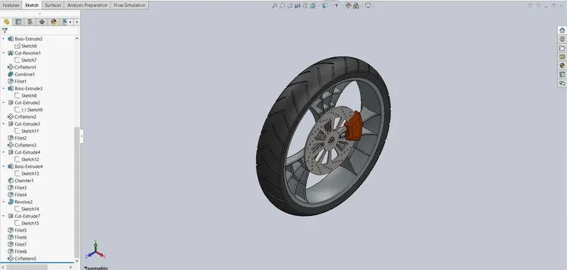
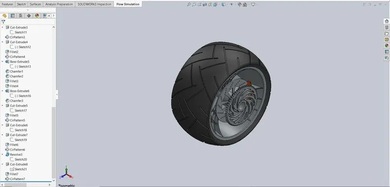
- Front Wheel:- Wheel is essential part of vehicle because it comes in direct contact with road & it transfers power from engine to road to propel vehicle forward. It also gives comfort against uneven road surface with the help of air tubes around its rim. Here front wheel is larger in diameter and smaller in thickness compared to rear wheel in American chopper bike. It is attached to front fork and is covered by fender.
- Process: Front wheel includes a tyre, spider web rim, a brake calliper and friction disk with air vents. First rim is created by revolving its cross-section drawing around a center axis. With its center hub, shape of web is extruded and material is removed by extrude cut. After that, 3 boss extrudes are created inside of web. To get final shape of spider web, revolve cut is used. Here another 2 copies are created with circular pattern. Required fillet is given here. Now friction disk is designed with required shape & air vents according to model parameters. A brake calliper is created with the help of extrude, fillet and chamfer options. At last, a rubber tyre is created with tyre treads around its periphery.
- Features used: Revolve, Extrude, Extrude cut, Revolve cut, Fillet, Chamfer, Circular pattern, Revolve cut, Combine
- Relation given: Coincident, Horizontal, Vertical, Mid-point, Intersection point, Tangent, Angle
- Material applied: Matte rubber for Tyre, Siena for Calliper, Chromium plate for Friction disk (Rotor), Carbon steel for Rim
- Rear Wheel:- Rear wheel in American chopper is wider and smaller in diameter compared to front wheel. It is connected with engine via chain drive.
- Process: The same process is used for designing rear wheel as for front wheel. Except in rear wheel, a chain sprocket alongside rotor and calliper is given. This sprocket is created with the help of revolve, circular pattern, extrude and fillet.
- Features used: Revolve, Extrude, Extrude cut, Revolve cut, Fillet, Chamfer, Circular pattern, Revolve cut, Combine
- Relation given: Coincident, Horizontal, Vertical, Mid-point, Intersection point, Tangent, Angle
- Material applied: Matte rubber for Tyre, Siena for Calliper, Chromium plate for Rotor, Rim and Sprocket
- Gas Tank:- Gas tank is used for storage of fuel in any vehicle. Here gas tank is attached with seat part.
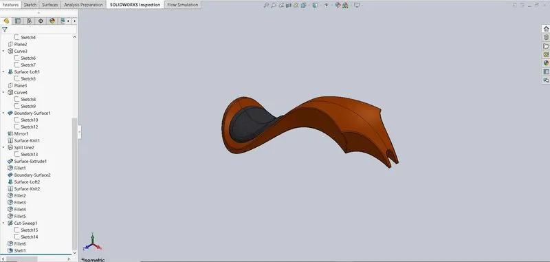
- Process: First, a path is created for surface sweep according to blueprint. Then Surface trim is used to remove extra material. Front side surface of gas tank is created with loft and backside surface is created with boundary surface. Now this half portion of tank surface is mirrored against mid plane. To join this two halves, Knit surface is used. To create a seat, Split is used on tank surface and then surface extrude is used for its 3D modelling. Some fillet is applied to it. Bottom surface of tank is also created with loft and then knit is used for joining these surfaces. Required fillet is applied. Now to position gas tank on chassis, some groove is required on front-bottom side of it, which is done by sweep-cut. In last, a shell feature is used for making gas tank hollow.
- Features used: Surface sweep, Surface loft, Boundary Surface, Mirror, Surface knit, Split, Fillet, Sweep cut, Shell
- Relation given: Horizontal, Pierce, Coincident, Vertical, on the edge
- Material applied: Grey cotton for Seat, Siena for Gas tank
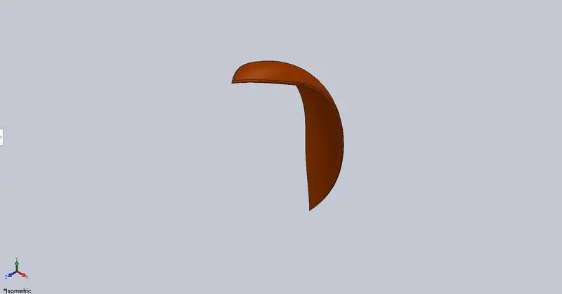
- Front Fender:- Fender is used for protection and cover for wheel. Front fender has less width compared to Rear fender.
- Process: Front fender is created by using revolve its cross-section around center axis with two limiting angles. Then its front and rear end is shaped according to dimension by using Split tool. Then some fillet is given around fender.
- Features used: Revolve, Split, Fillet
- Relation given: Horizontal, Vertical, Symmetrical, Coincident
- Material applied: Siena
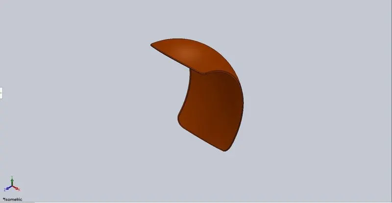
- Rear Fender:- Rear fender is wider compared to Front fender. It covers rear wheel and supports gas tank at seat portion.
- Process: Same process is applied for Rear fender as Front fender. Except under side of rear fender is given “Shell”.
- Features used: Revolve, Split, Fillet, Shell
- Relation given: Horizontal, Vertical, Symmetrical, Coincident
- Material applied: Siena
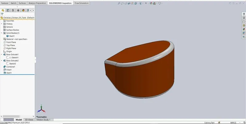
- Oil Tank:- It is used to store oil which is utilized for lubrication, cooling and cleaning purpose in various parts of an engine in vehicle.
- Process: Oil tank is generated with combination of two extrude bodies - one wedge body and other one is simple extrude. Some fillet around edges is applied. Then to make it hollow, Shell is applied to body extrude.
- Features used: Extrude, Combine, Fillet, Shell
- Relation given: Vertical, Symmetric, Tangent, Coincident
- Material applied: White for fillet edges, Siena for Oil tank
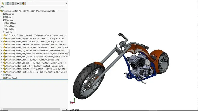
Assembly of American Chopper:
Here isometric view of American Chopper is shown below. In new assembly file, first chassis is inserted and fixed to certain point. Then engine is mounted on it using different mates. Exhaust pipes are modified to remove any interference with other parts. Chassis is chamfered due to interference with chain. For assembly, two pedals are required. So one pedal is mirrored and attached. Then kickstand is modified and attached to chassis. After that, transmission belt is assembled between engine and gearbox with mates. Here oil tank is attached between engine and seat. After this, rear wheel and rear fender is attached to chassis. Chain is connected between rear wheel sprocket and gear box. After that, gas tank is inserted upon engine. Now, Front fork is attached in front part of chassis. Here front wheel and front fender is attached to front fork as final assembly parts. Different materials for parts are also applied.
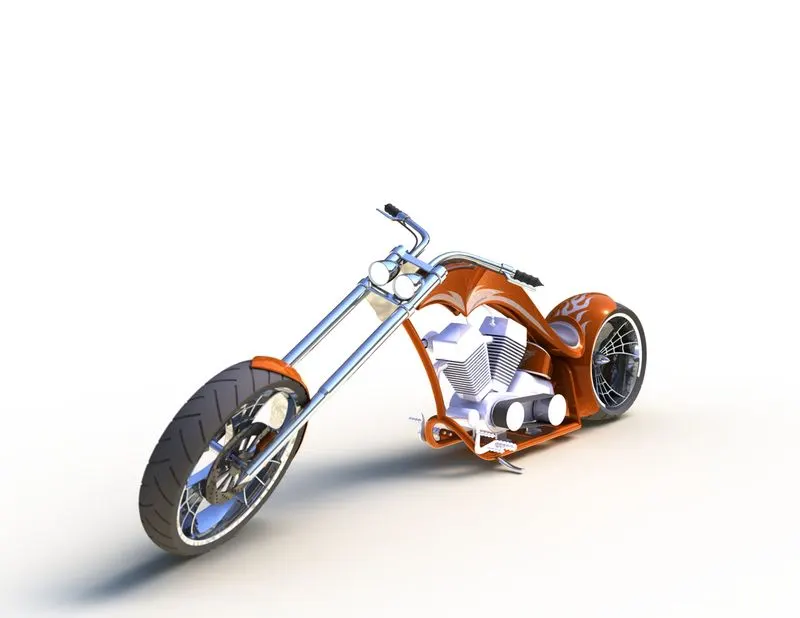
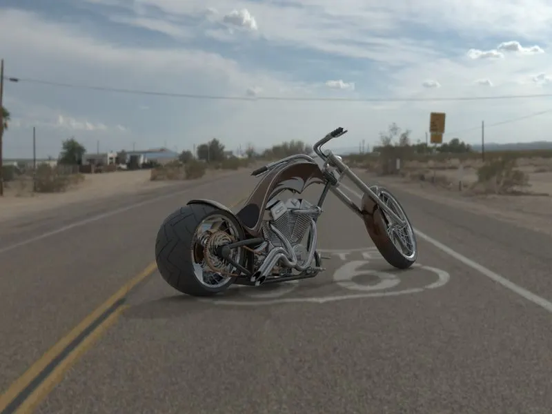
Rendering of American Chopper:
For rendering purpose, one can use of Photoview 360 or Solidworks Visualize. Here American chopper is rendered with Solidworks Visualize. Different appearance are used for parts in assembly.
A new environment “Route 66” is used for Final render by applying different options such as height, size, gamma, brightness, snap to floor, etc. ‘Good’ Quality is used for rendering. Final render image is rendered with ‘Fast’ option with 100 pass and resolution of 1440 X 1080.
Conclusion:
In modelling & rendering of American Chopper, I have learned to create various 3D models design, assembly & a good render image of it in Solidworks as well as Solidworks Visualize.