Week 8 - Challenge 3 - Switch Bezel Design
DRAFT ANALYSIS OF SWITCH BEZEL
Objectives:
To create Class-A surface, Class B and C surface
To create tooling axis for the model
To generate solid part from surface model of SWITCH BEZEL
To perform draft analysis on given SWITCH BEZEL surface as well as part model
Steps of creation of Class-A surface of SWITCH BEZEL model:
Create a Class-A surface of SWITCH BEZEL by connecting different surfaces using JOIN or BOUNDARY command. Class-A surface will be seen yellow as shown in figure. Maximum join limit should be upto 0.003 mm.
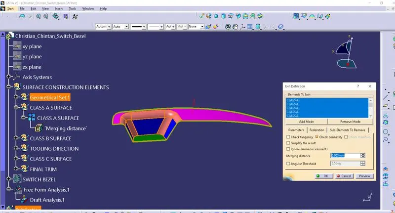
If any green line is seen on surface it means discontinuity exists. To remove all discontinuity use FILL option. Apply different colours to BASE, BEZEL REST SURFACE as well as WALLS surface for identification purpose.
Steps of creation of tooling axis for Class A surface of SWITCH BEZEL:
After joining this model, a tooling axis needs to be created.
Tooling axis is created for applying same draft over model regardless of position of surfaces on it.
First, extract BASE from Class A surface. Create a center point as well as a new axis system on it.
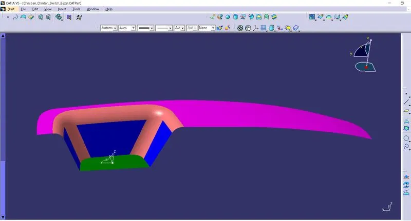
Then use YZ plane from new axis and center point to create intersection of surface in Y direction. Create lines on two inclined lines of this intersection & then use it to generate a bisecting line between them.
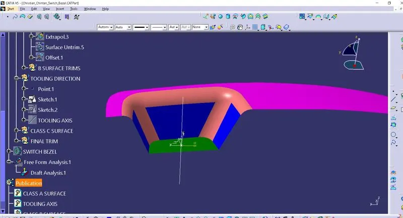
Now create an intersection using ZX plane from new axis system and center point. Here only one inclined line is present. So create another line and give angle between these lines about 3 degrees.
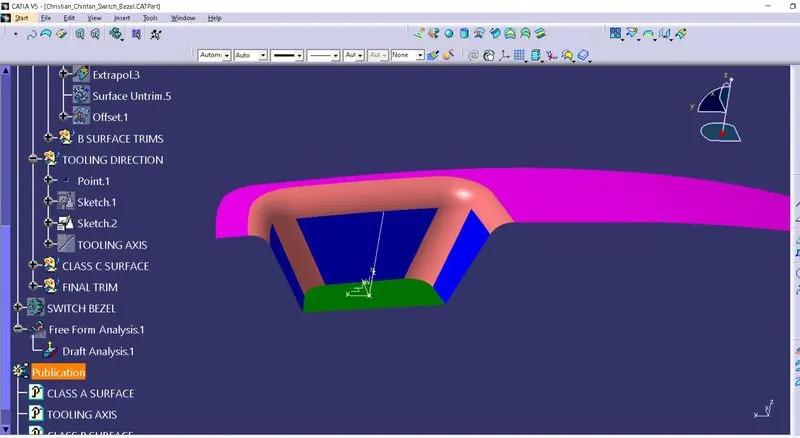
Now, use lines from first and second intersection and make a bisecting line using them. This will be our TOOLING AXIS. Apply colour, thickness and line type to it.
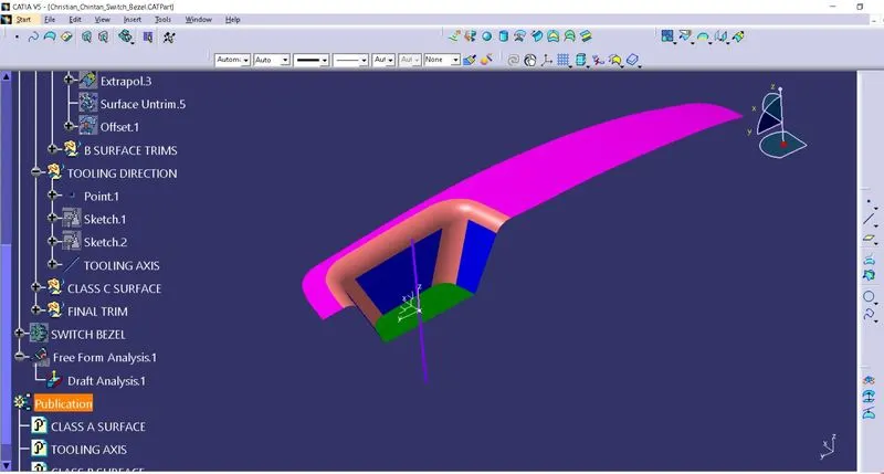
Publish SWITCH BEZEL Class-A surface as well as TOOLING AXIS by using “PUBLICATION” from Tools menu.
Steps of creation of Class-B surface of SWITCH BEZEL model:
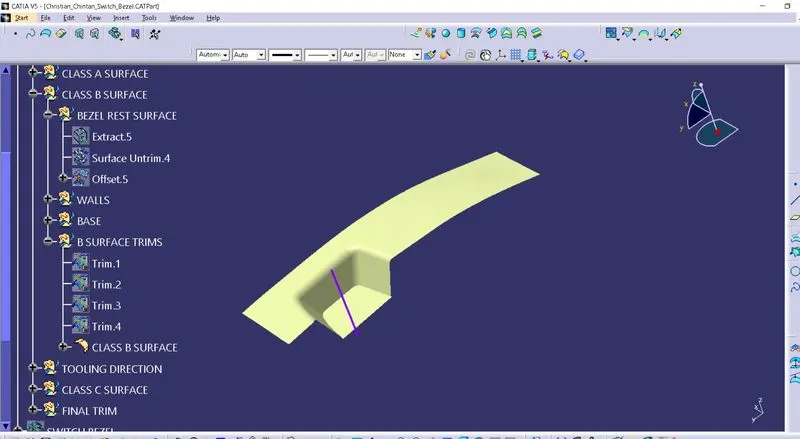
Here consider thickness of part about 2.5 mm. Also, BASE part is extracted while creation of tooling axis. Now, untrim and extrapolate it. Then offset it downwards about 2.5 mm.
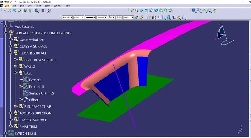
After that, select 3 blue coloured WALLS surfaces from Class A surface. Untrim & extrapolate them and offset them about 2.5 mm.
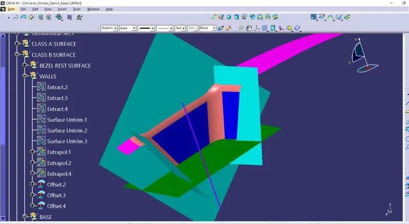
Now, comes the BEZEL REST SURFACE. Extract & untrim it. Then offset it downwards 2.5 mm.
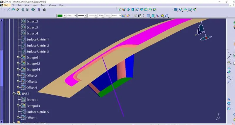
Trim all - BASE, WALLS & BEZEL REST SURFACE surfaces with respect to Class A surface. Give required edges fillet of 15 mm.
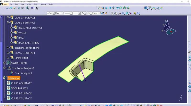
This will be our B surface. Rename this last fillet as “Class B surface” and use PUBLICATION to publish it.
Steps of creation of Class-C surface of SWITCH BEZEL model:
C surface comes into play when it is needed to connect Class A surface and Class B surface.
Here first use multiple extract with tangent continuity to select edges of Class A surface.
Then create boundary of these 2 multiple extracts by using BOUNDARY option with selecting two end points.
Use smooth curve options for these 2 boundaries.
Now create a sweep surface by using sweep with draft direction. Use Tooling axis as direction line. Give 3 degrees draft to these 2 smooth curves selected. Direction of sweep should be outside direction and towards Class B surface.
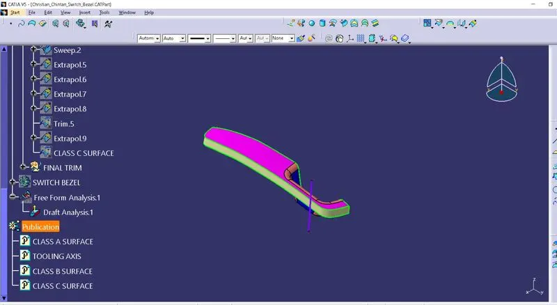
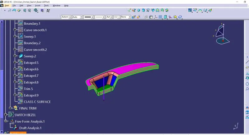
At this stage, if any gap seen in surface, use extrapolate and trim to remove it.
In this way, C surface is created.
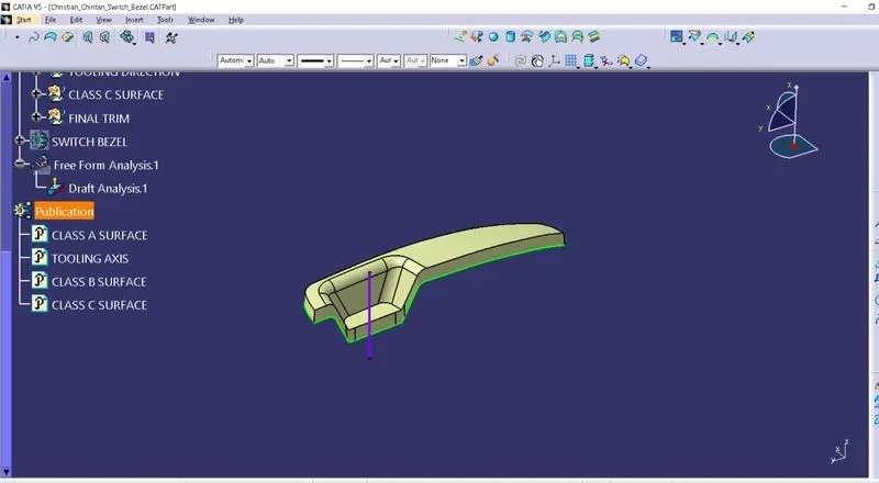
Now, join Class A surface with a C surface. Trim it with Class B surface and name it as final trim. Check any gaps remained in this final trim by using boundary option.
In part design workbench, use close surface to generate solid SWITCH BEZEL part from Class C surface.
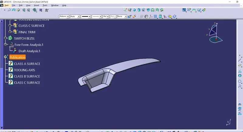
Steps to do draft analysis on SWITCH BEZEL model:
Go to insert > analysis > feature draft analysis or directly click on Feature draft analysis icon from menu.
First select compass option from pop-up menu to set axis system coincide with tooling axis.
After setting up axis on tooling axis, use lock option to fix it.
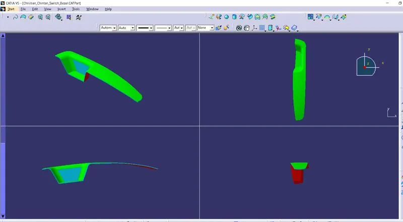
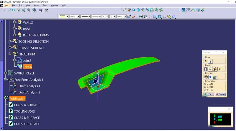
Surface model will turn into green colour surface, which shows that draft for model is in limit upto 3 degrees. Here I have given green colour for 3 degree draft, light blue for 0 and red colour for negative draft.
Run quick analysis on model and if any draft angle is more than limit, then one can apply new value of it in pop up box.
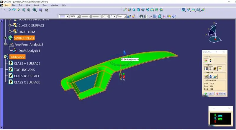
Full analysis shows different draft angles with different colours as shown in figure.
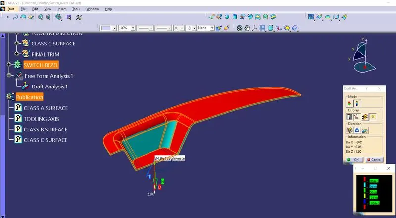
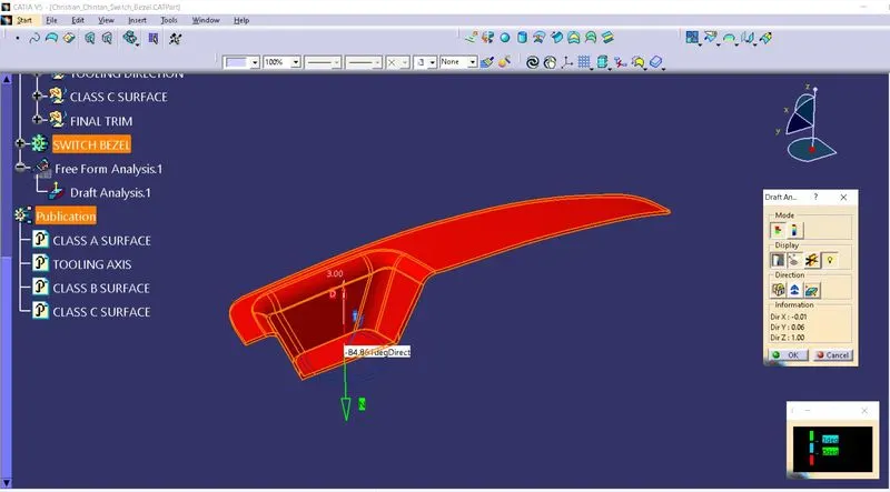
Here is an example of INVERT DRAFT DIRECTION analysis.
Below image shows the different views of draft analysis of SWITCH BEZEL model.
Draft analysis of Surface model:
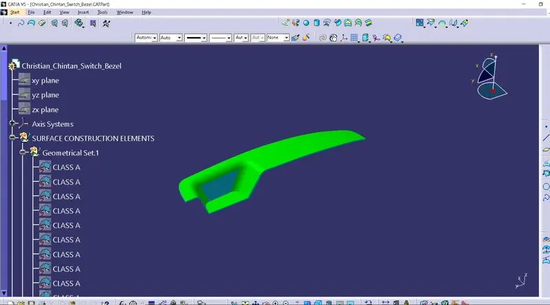
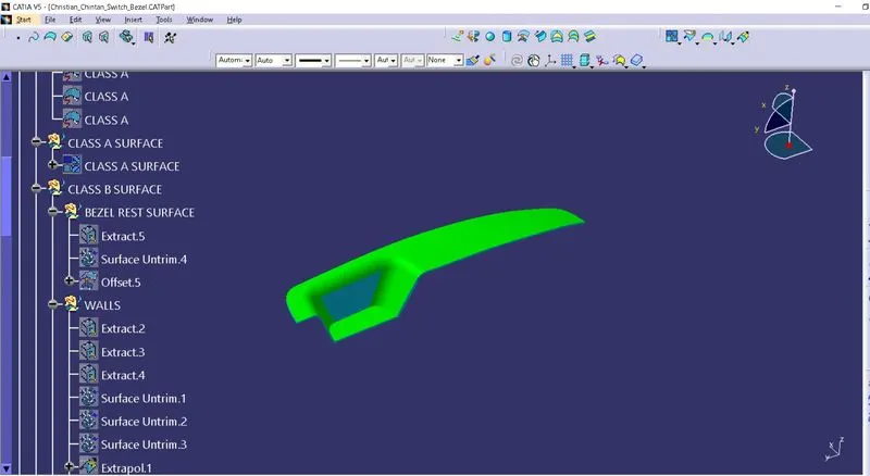
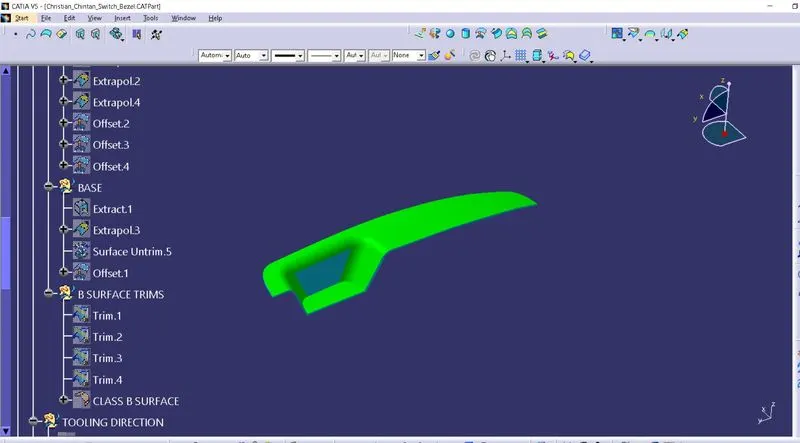
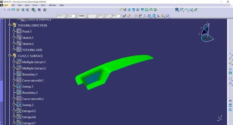
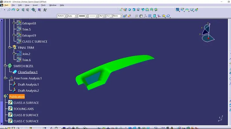
Here are snaps of feature tree of this SWITCH BEZEL model:
Conclusion:
In this challenge, I have learned about tooling axis creation, Class A, Class B & Class C surface creation and draft analysis for given SWITCH BEZEL model.