Week 9 - Project 1 - Door Applique Design with Engineering Features
Create the Door Applique Plastic component through the given Class-A surface.
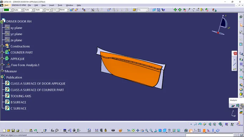
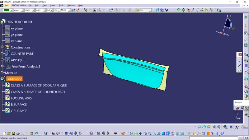
Given CLASS A SUREFACE of door applique and counterpart
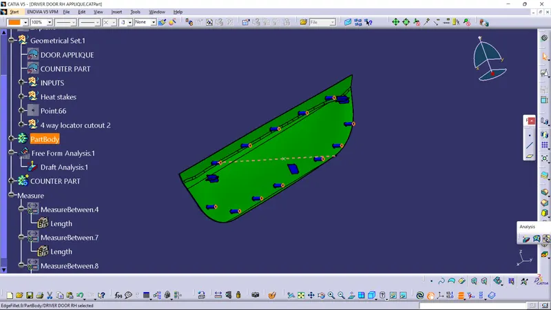
- Below images are Position sketches of 4 WAY LOCATOR, 2 WAY LOCATOR and HEAT STAKE are Iso-constrained
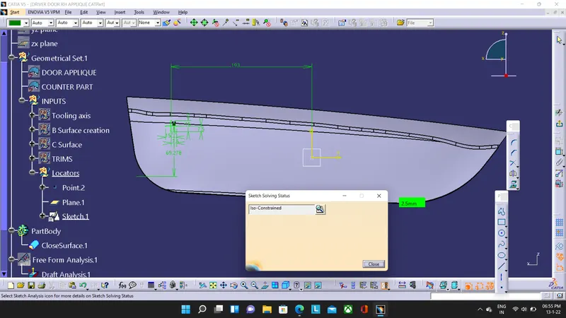
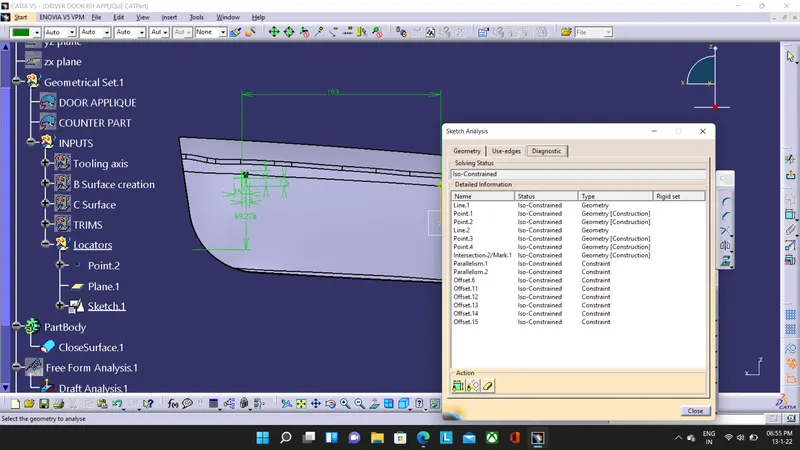
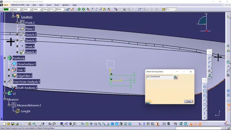
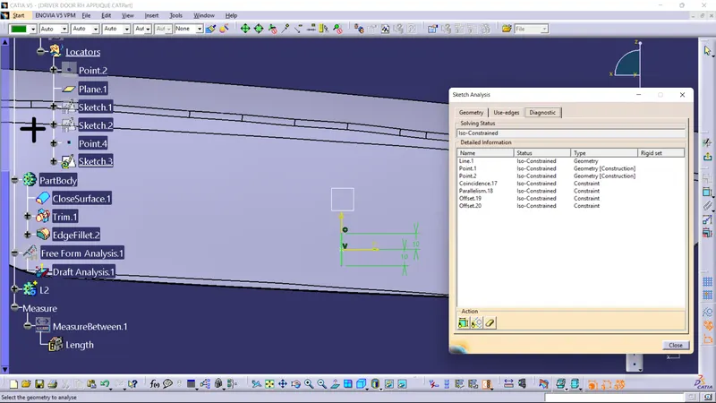
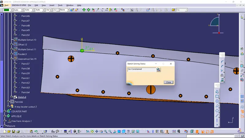
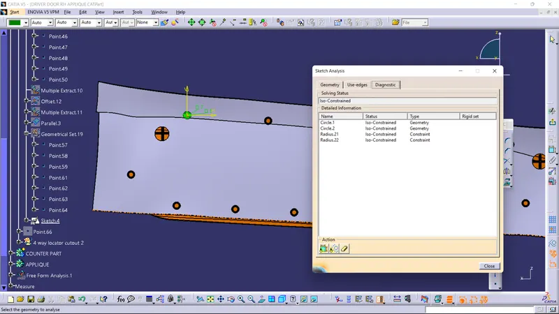
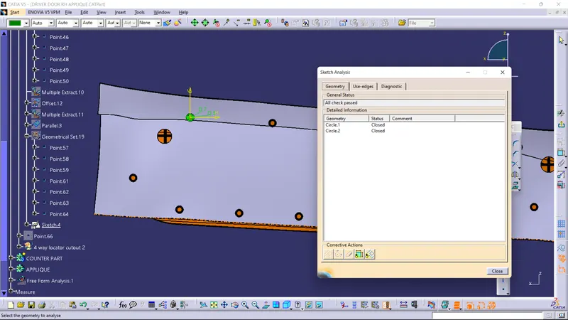
- Tree Structure having geometrical set as "INPUTS"
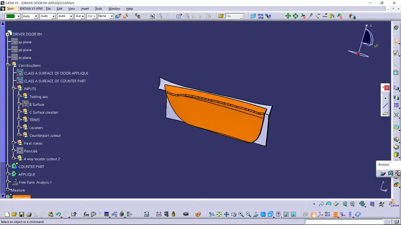
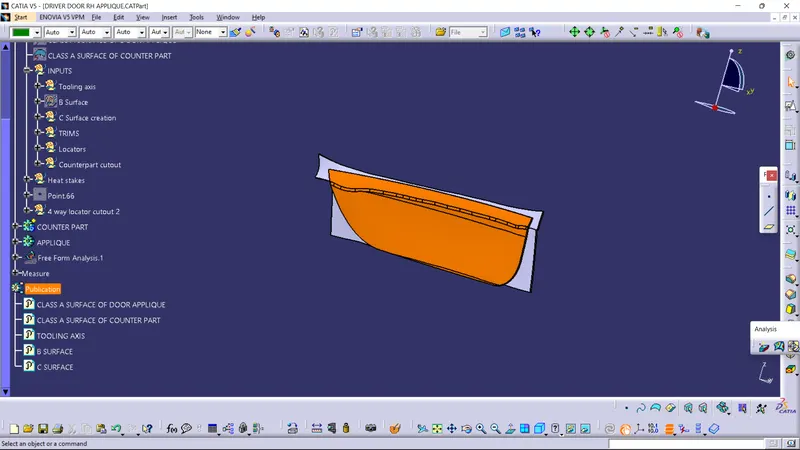
- Report
- A detailed report should be done explaining the draft analysis and the tooling axis creation.
- An explanation should be given on the way of creating the tooling axis particularly the Bisecting method.
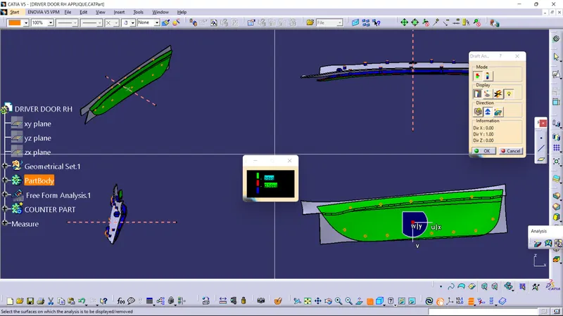
Draft analysis done on the given CLASS A SURFACE and TOOLING AXIS created along Y direction and through its midpoint ,perpendicular to the Class A Surface
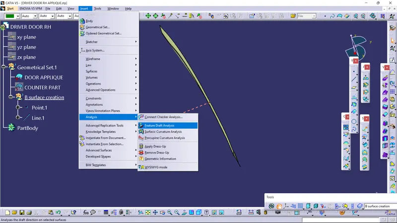
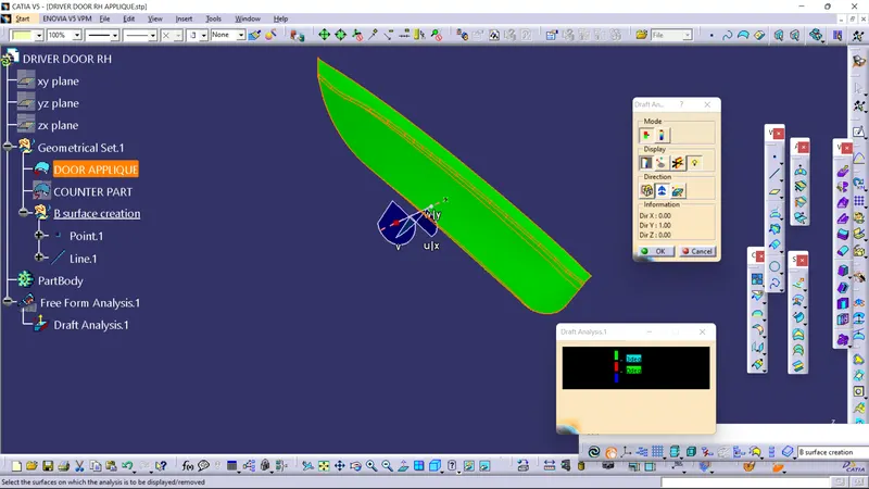
Class A surface shown in various iterations and compass inversion to clear the component on the other side
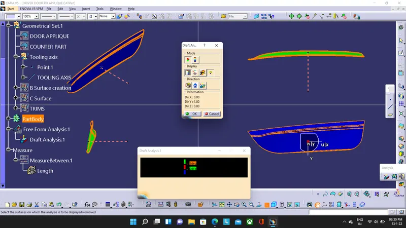
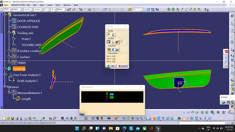
Below image shows The DOOR APPLIQUE draft analysis cleared
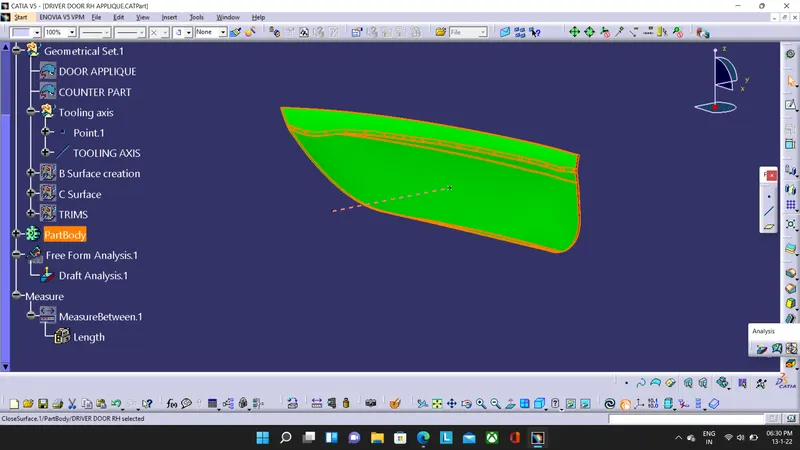
- CREATION OF 4 WAY LOCATOR,2 WAY LOCATOR and Design rules to be followed are as follows
- Create 4 way locator sketch in position sketch and have to be Iso-constrained
- PAD the sketch after creating a body in the tree structure
- Draft angle of 0.5 deg is given on its sides,neutral element being its lower face
- Chamfer angle 45 deg on its edges
- Minimum Edge fillet given as 0.3 deg
- using TRANSLATE command another locator can be positioned on the door applique elsewhere as required by the designer.
- Cutout to be made on the counterpart so sketch created ensuring minimum gap between 4 way locator and counterpart
- PAD the cutout sketch and select the counterpart,use REMOVE option.Cutout made
- Minimum gap for a locator should be 0.05 mm per side and 0.1 per side is also acceptable
- CREATION OF Heat stakes and Design rules to be followed are as follows
- Heat stake used to seal the components to the other by heating the component while its pressed againt each other
- Create a sketch in position sketch for heat stake and have to be Iso-constrained
- PAD the sketch after creating a body in the tree structure
- Minimum Edge fillet given as 0.5 deg
- using Point to Point option on TRANSLATE command another heat stake can be positioned on the door applique elsewhere as required by the designer.
- Point 1 should be the point of parent heat stake and Point 2 should be the desired location of the heat stake
- Cutout to be made on the counterpart so sketch created ensuring minimum gap between heat stake and counterpart
- PAD the cutout sketch and select the counterpart,use REMOVE option.Cutout made
- Heat stake as per design rules should be second in operation so has to be smaller in length compared to our locator in the above design
- The clearance gap between the heat stake and counterpart should be 0.05 per side and 0.1 per side is also acceptable
Below images show that the 4 way locators, 2 way locator and Heat stakes created following design rules.
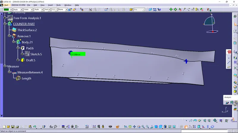
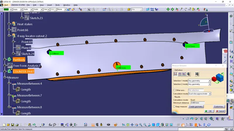
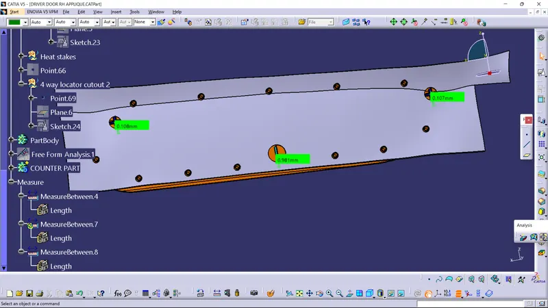
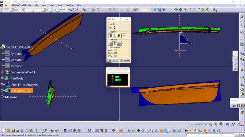
Draft analysis done on the counterpart and the Door applique component
Draft analysis angle given as 3 deg
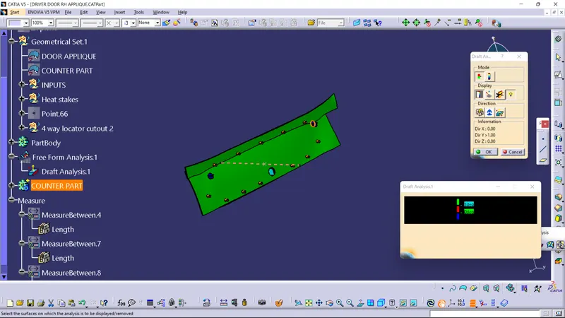
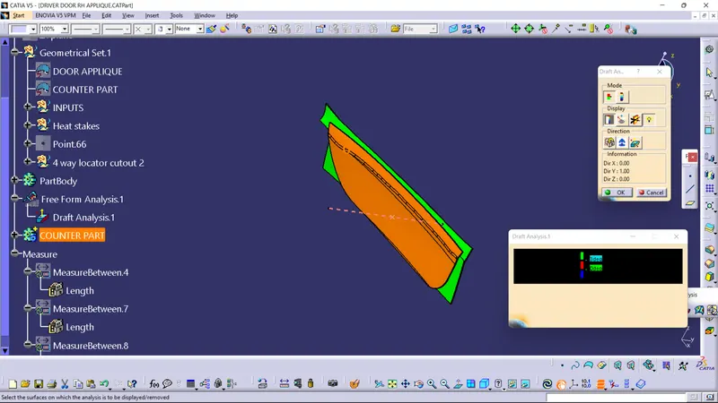
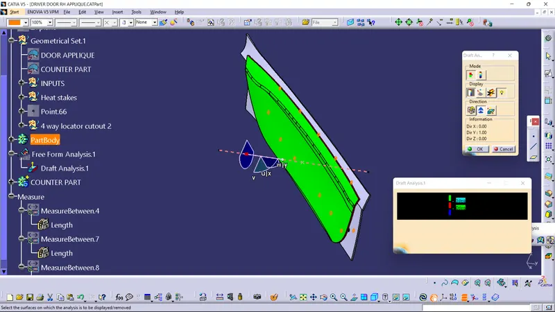
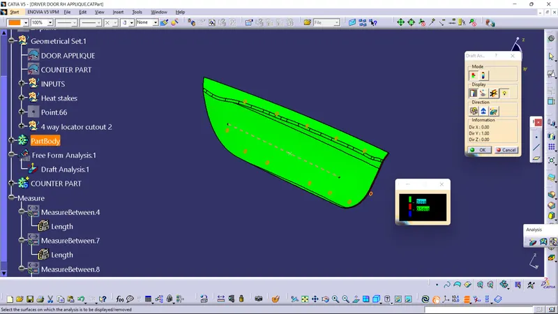
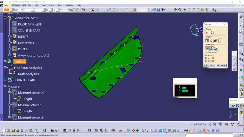
Door applique draft analysis cleared and shown in various iterations in the below image
Counterpart draft analysis cleared and shown in various iterations in the below image
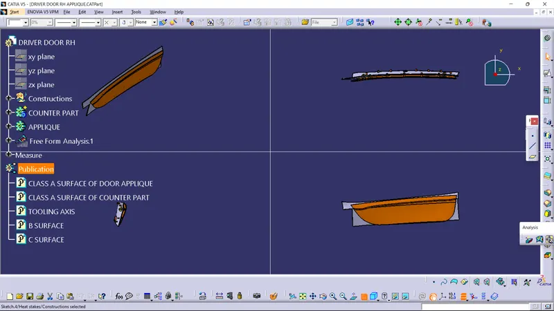
- Screenshots of the completed design in various orientations (Isometric, Front, Side, and Top View)
NOTE:The CATpart is submitted as an attachment below in ZIP file format
THANKYOU.