Week 9 - Project 1 - Door Applique Design with Engineering Features
Aim:
Creating a Door applique with class A,B and C surfaces and providing the heat stakes,4 way and 2 way locators on it.
Tools Used:
- Line
- Point
- Circle
- Extrapolate
- Trim
- Edge fillet
- Parallel surface
- pad
- Join
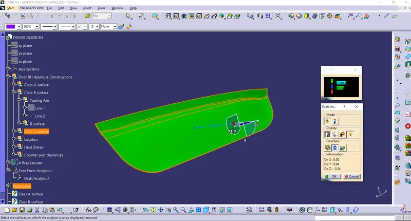
- Draft Analysis
Draft Analysis:
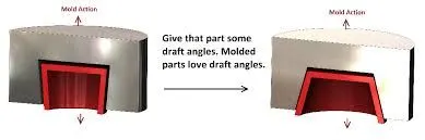
- On Injection molding the parts which are getting ejected will have some defects and very difficult to remove from the cavity, So to make easier and reduce the defects this draft analysis is used.
- The Below pic shows that the parts on the cavity with normal in shape and another is drafted.
- Basically the plastic components should be drafted at 3deg and for a sheetmetal components the draft angle should be 7 deg.
Tooling Axis:
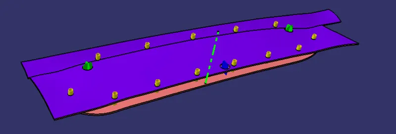
- Tooling axis represent the tooling direction of the mould part.so that the part can travel on the axis to achieve the draft angle.
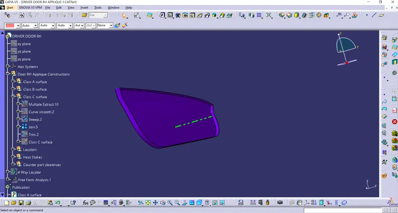
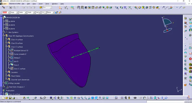
- The below fig green line represented as tooling axis by bisecting the two lines with respect to the surfaces the tooling axis will be provided.
- Creating the tooling axis we need to intersect the class A surface.
4 Way,2 Way locators and Heat stake:
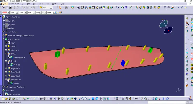
- Locators are used as an guide reference which helps to attach the main part into other plastic or steel parts.
- Heat stake helps to attach with the other plastic part with the main part and it will be welded into single part.
- Its purpose is to locate the mold in the correct position.
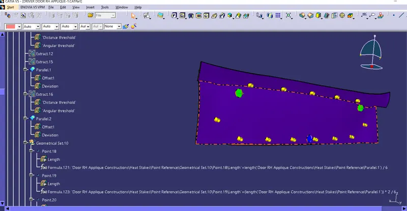
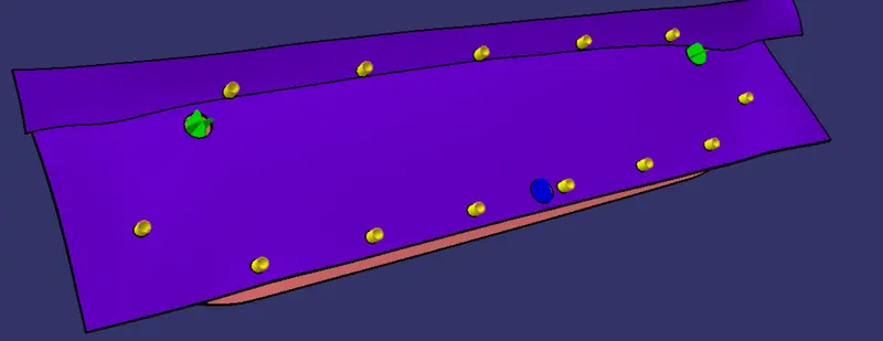
- The Green and Blue colored parts are locators and yellow colors are heat stakes.
Procedure:
- After creating the Tooling axis extract the surfaces to create Class B surface and trim the excess surface that are intersecting with Class A surfaces and offset it to 2.5mm and provide edge fillets accordingly.
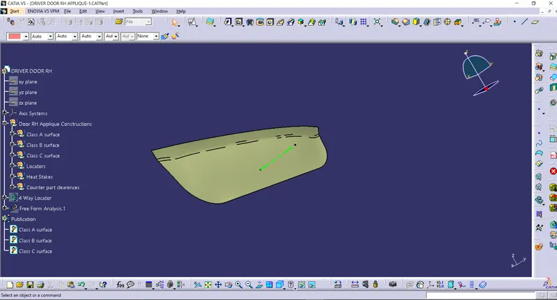
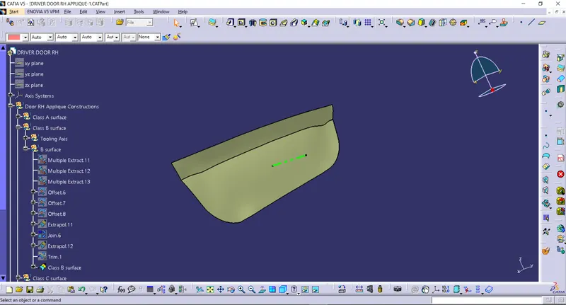
- Create a Class C surface by extracting the boundry of the class A surface and extrapolate to certain length and sweep it to 3 deg and join with Class A surface.
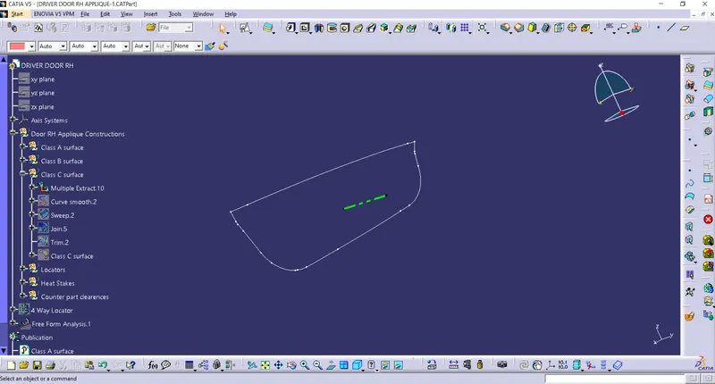
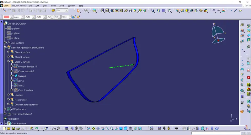
- Trim the Class A,B and C surfaces to get closed surfaces and join them into single part.
Draft Analysis:
- Create a 4 way locators,2 way locators and heat stakes by sketching and extrude it and adding edge fillets and chamfer
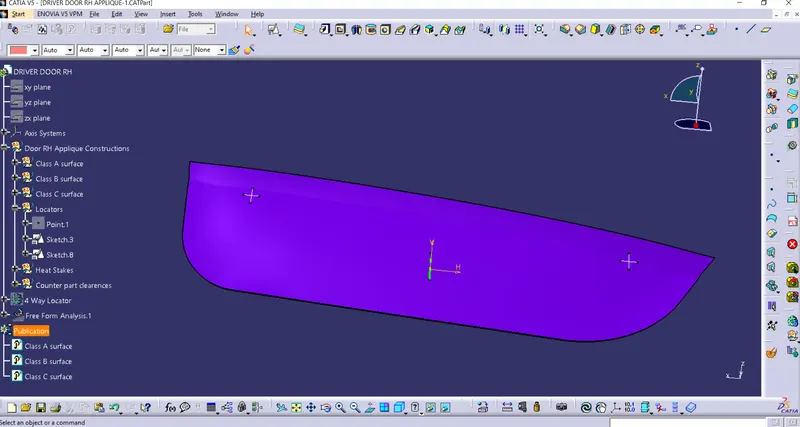
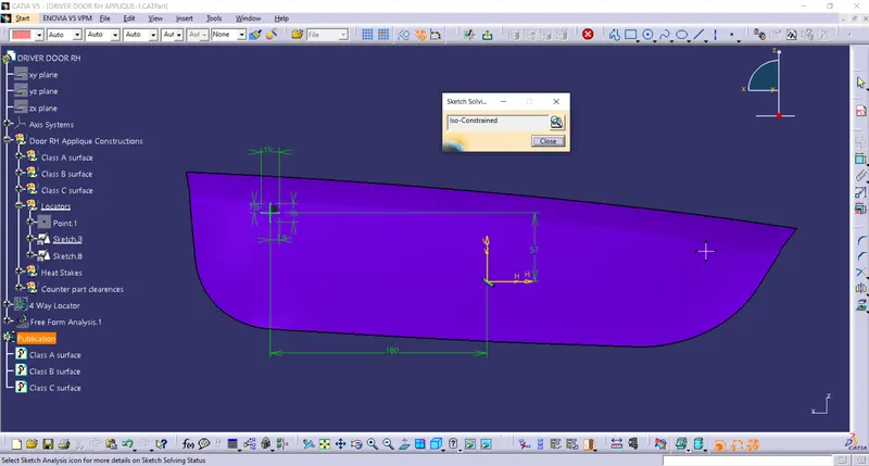
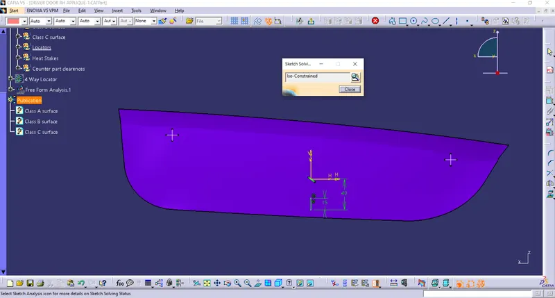
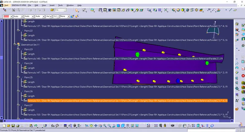
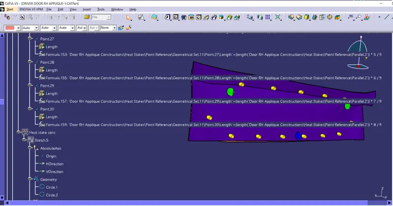
- For creating heat stakes boundry should be created by parallel surface to 2.5mm and create a particluar points and sketch,extrude it.
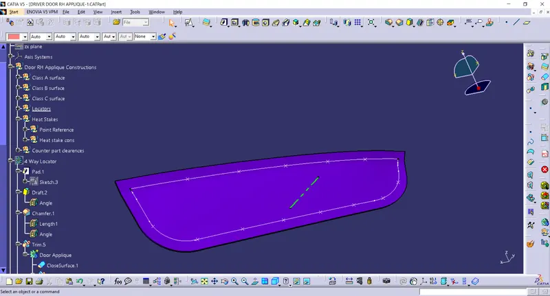
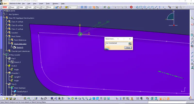
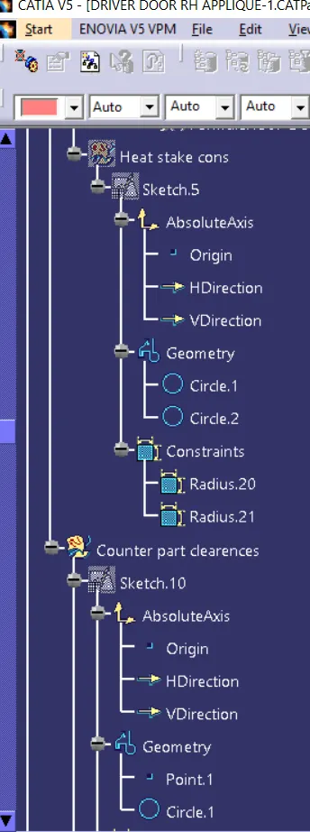
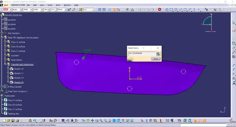
- Create a counter point clearances so that heat stakes will locate on the region and paste the sketch and translate it for further heat stakes.
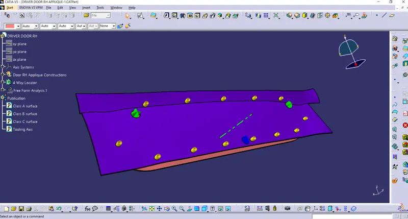
Views:(Isometric,Top,Front,Side)
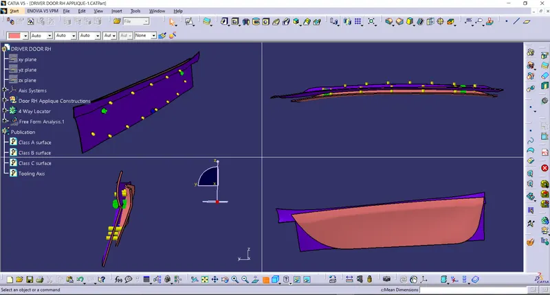
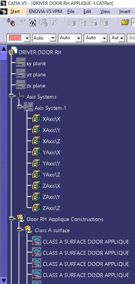
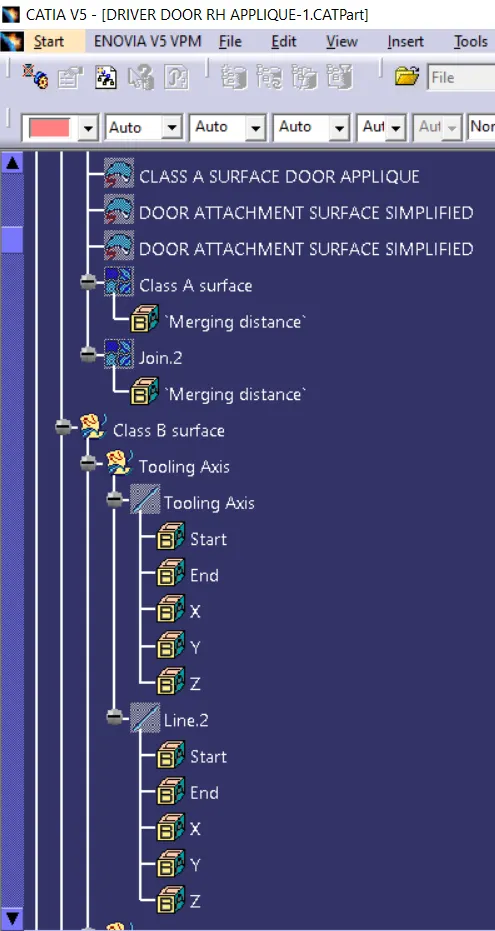
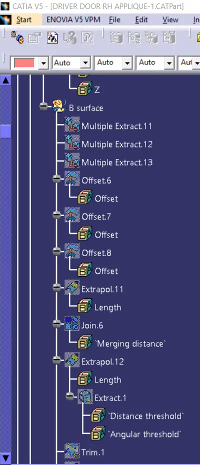
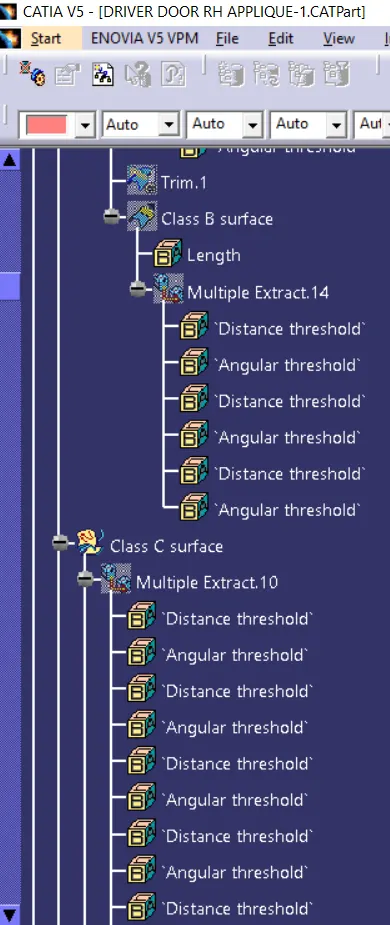
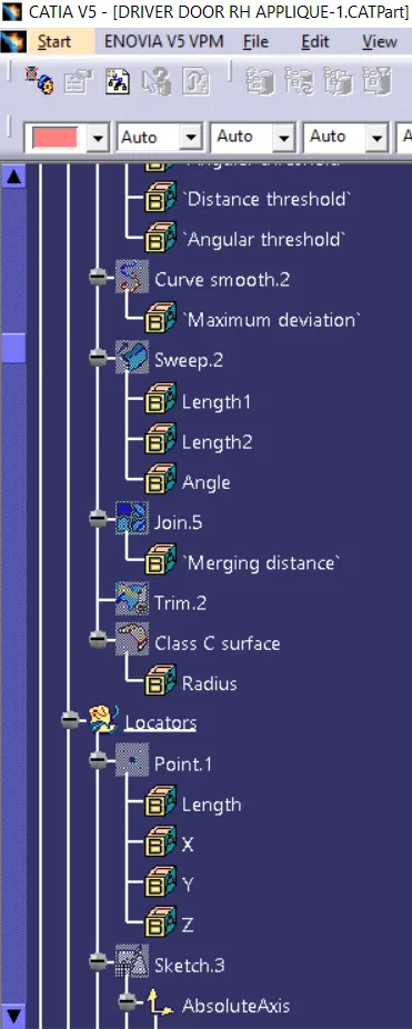
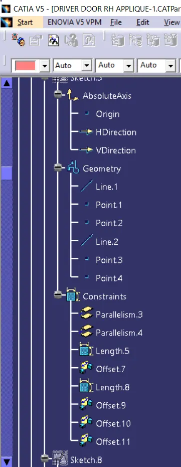
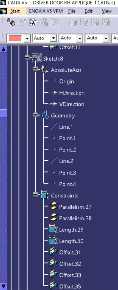
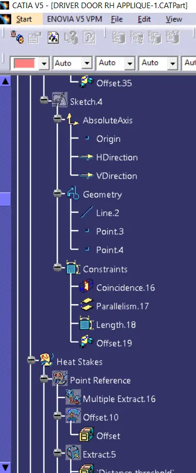
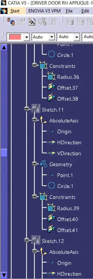
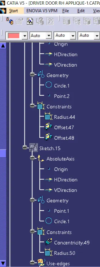
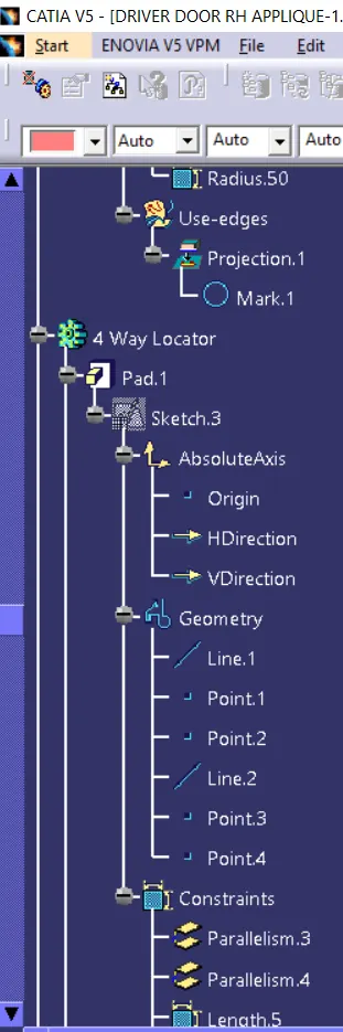
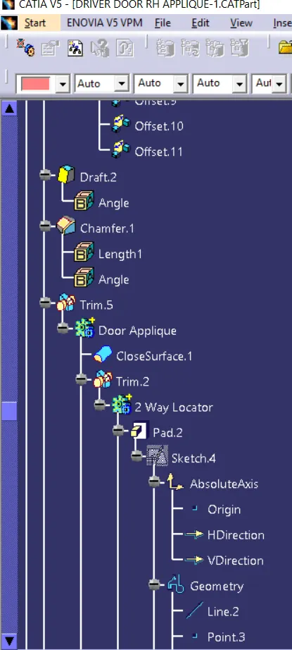
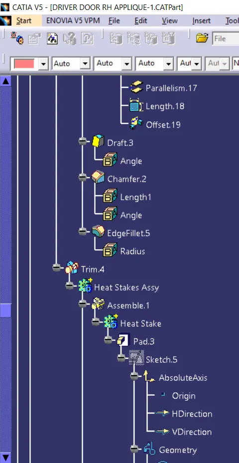
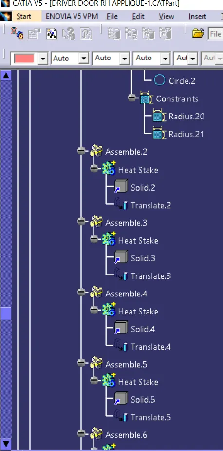
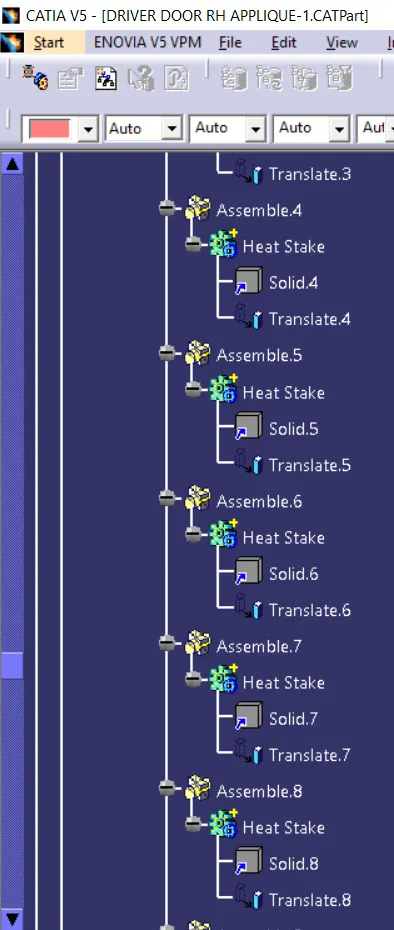
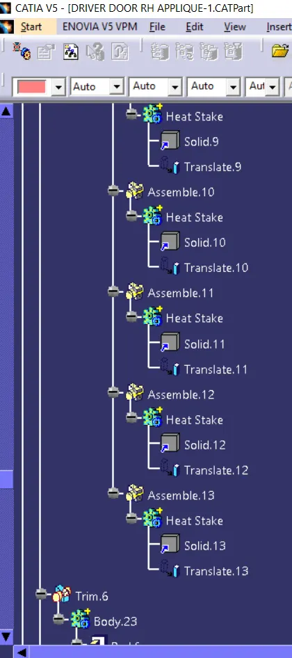
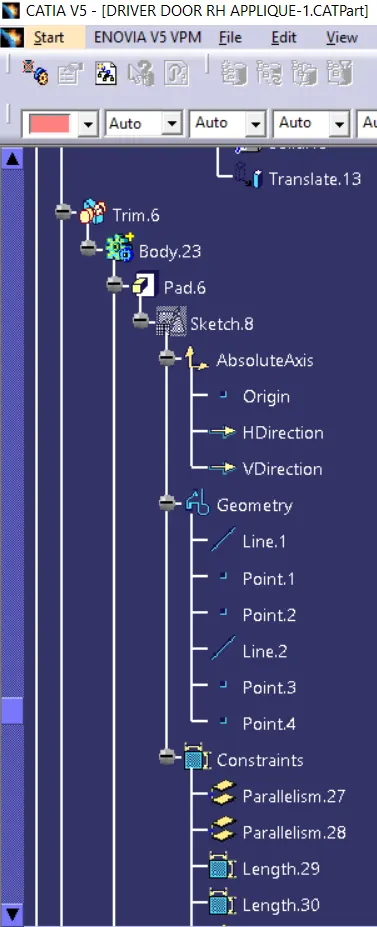
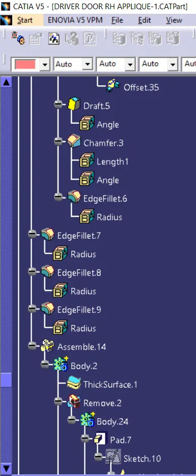
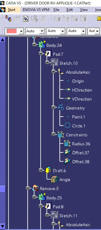
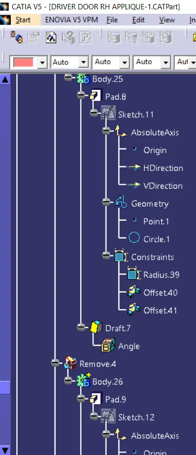
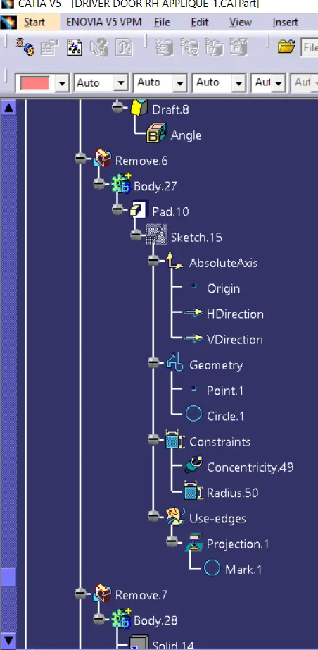
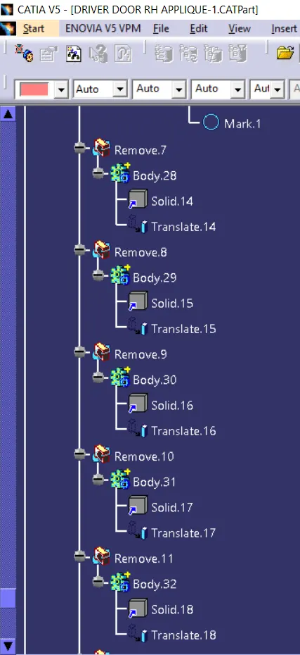
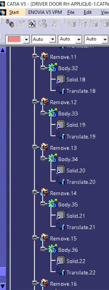
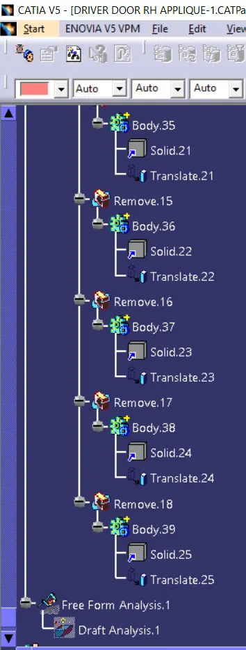
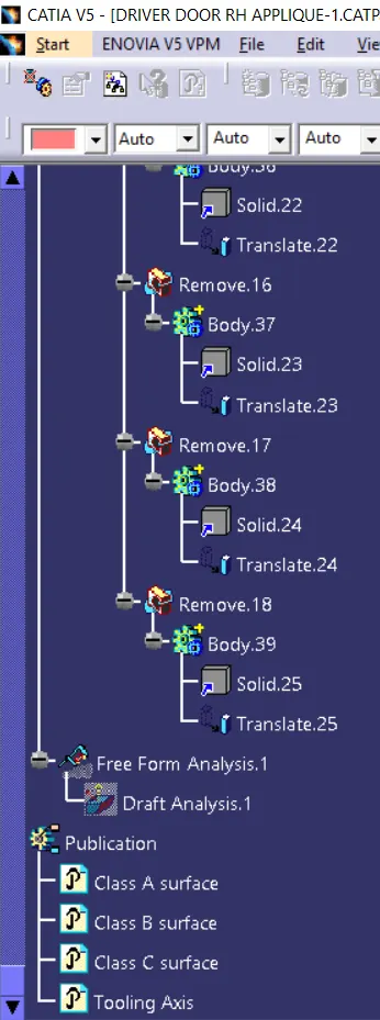
Feature Tree Manager: