Photo Realistic Rendering
Design of American chopper bike using solidworks
OBJECTIVE:
To create a model of American chopper bike using solidworks and also assemble of the parts and giving them a realistic 3D visualization for the model.
Introduction:
- American chopper is started in year 2003 and was one of the most popular motorcycle in America and has motorcycling shows of the OCC (Orange Country Choppers) for further details https://en.wikipedia.org/wiki/American_Chopper
- In this project we will be designing an individual chopper component, assemble the modelled component and finally a 3D visualisation appearance for the model.
Features Description:
- Fillet:
Fillet creates a rounded terminal or external faces on the part.you can fillet all edges of a face.
2. Dome:
It can be applied to the outside faces of the irregular faces and produces a smooth curvature on the faces
3. Offset:
It create an same sketch with different scale values either to have inside the sketch or outside the sketch
4. Extrude Boss:
It is a feature to convert a 2D sketch into 3D sketch
5. Lofted Boss:
It generates a complex geometry in a single feature by interpolating surfaces between various cross sections of a model.
6. Split:
It is a feature to cut or seperate the surface or bodies in the sketch,You can able to split faces on multiple bodies
7. Trim:
It helps to remove the excess line or geometry in the sketches and can remove 3D sketch.
8. Revolve:
It is similar to the boss extrude but here it will create an revolved(round) shape extrude with an controleld angles.
9. Dynamic mirror:
It creates a same selected entites with the help of construction line or reference line
10. Combine:
As the name prefers combining the two or more Bodies into a single body.
11. Pattern:
This feature creates a pattern for the selected entities these can be in linear,circular way
12. Lofted surface:
These are the surfaces generated by multiple 3D curves creating a smooth tangency between the selected curves.
13. Swept surface:
These are the surfaces generated from a section curve positioned along a path.
14. Surface Knit:
It is used to knit the two free edges of the surface together.Also it reduces the gap between the two edges of the surface.
15. Extend surface:
It is similar to the trim future but here it will create the line or extend from the created sketch,Here we can also extend the surface of it.
PART MODELLING:
It is a process of modelling an individual part or object, In this case, we have some parts to model the chopper bike the list of part models are given below
- Transmission belt
- Kickstand
- Front fender
- Rear fender
- Chain
- Oil tank
- Pedal
- Front wheel
- Rear wheel
- Front fork
- Chassis
- Engine
- Gas tank
Note:
- Before starting the part modelling make sure that you have selected the proper dimensioning units, planes, sketch tools, views are activated
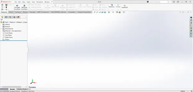
- The above image is an part modelling window where we can model the part or an object
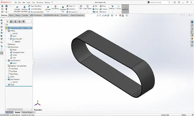
- Transmission belt:
Transmission of power from one shaft or one place to another with the help of the belt.
Features and Tools used:
Line
3 point arc
Fillets
Boss extrude
Views:
Isometric view:
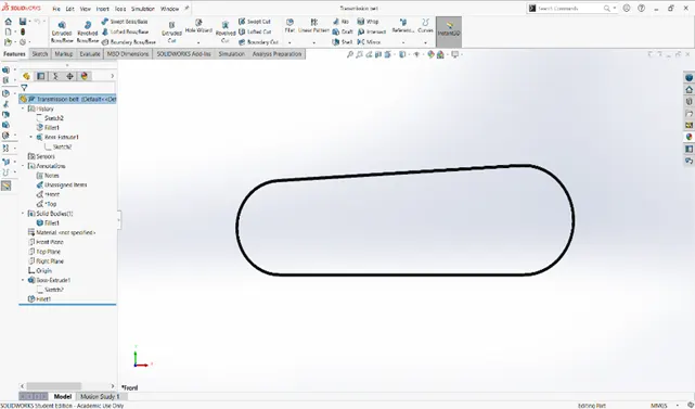
Front view:
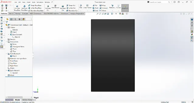
Side view:
2. Kick stand:
It is used to support the bike on the surface it usually used on parking the bike, so that it prevents the bike falling aside to near by object or a person.
Features and tools used:
· Spline
· 3 point arc
· Boss extrude
· Dome
· Cut extrude
· Fillet
· Circle
· Split
· Loft
Views:
Isometric view:
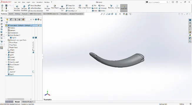
Front view:
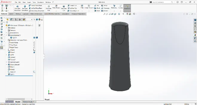
Side view:
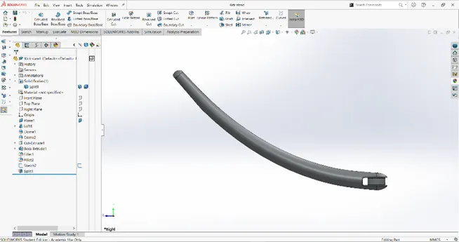
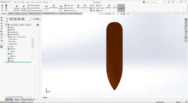
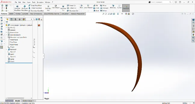
3. Front fender:
This part is located in the front side of the bike above the front wheel it act as an frame for the wheel and to prevent from dirt obstacles like mud, sand come from the rotating wheel.
Features and tools used:
Spline
Line
Trim
Fillet
Revolved boss extrude
Split
Views:
Isometric view:
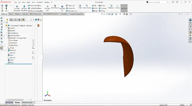
Front view:
Side view:
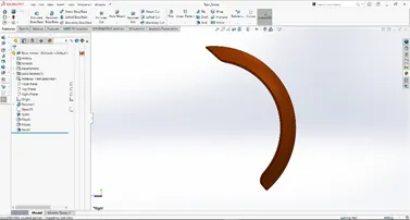
4. Rear Fender:
This part is located in the Rear side of the bike above the Rear wheel it act as an frame for the wheel and to prevent from dirt obstacles like mud, sand come from the rotating wheel.
Features and tools used:
Spline
Shell
Fillet
Appearances
Revolved boss extrude
Split
Trim
Views:
Isometric view:
Front view:
Side view:
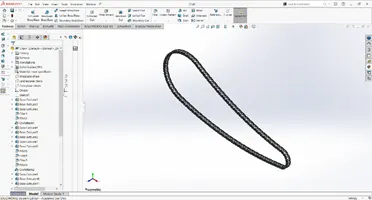
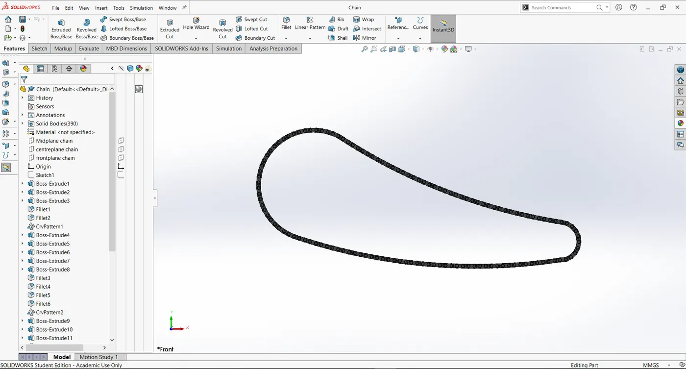
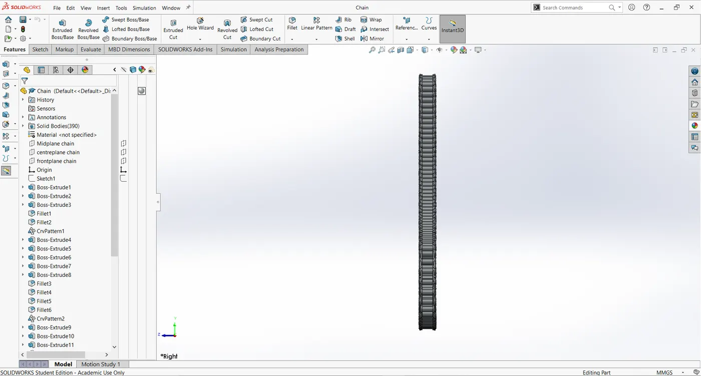
5. Chain:
A bike chain is a roller chain that transfers power form the engine to the drive wheel (Rear wheel).
Features and tools used:
Spline
Circle
Circular pattern
Trim
Boss extrude
Blocks
Fillet
Mirror
Views:
Isometric view:
Front view:
Side view:
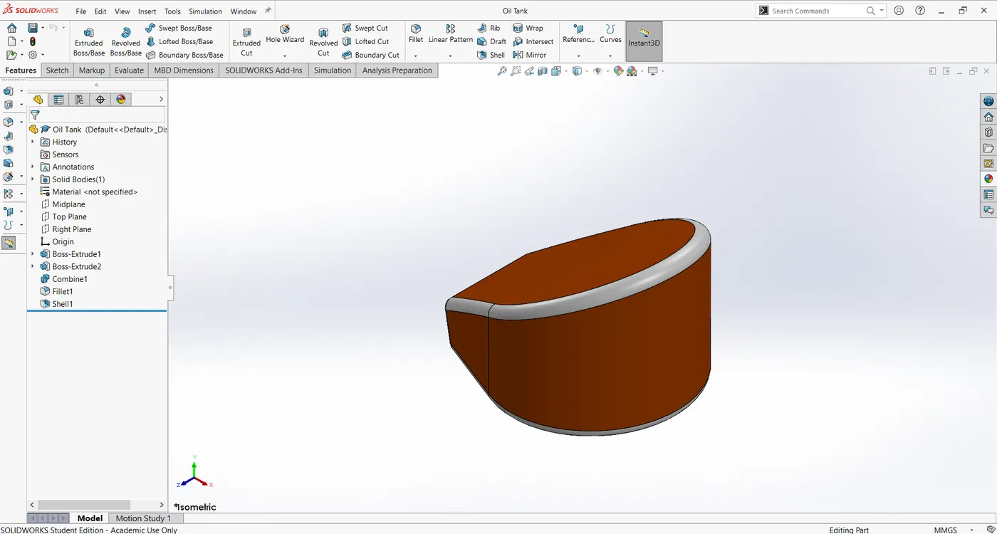
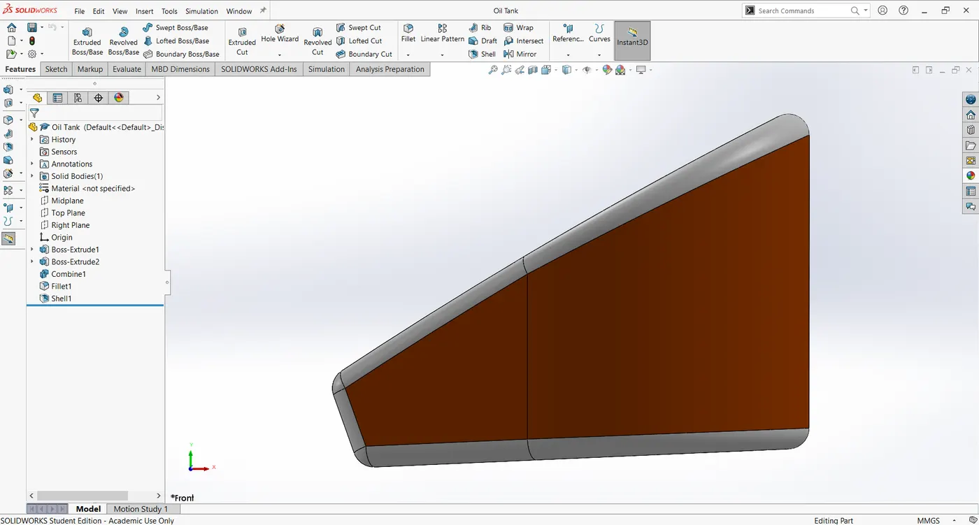
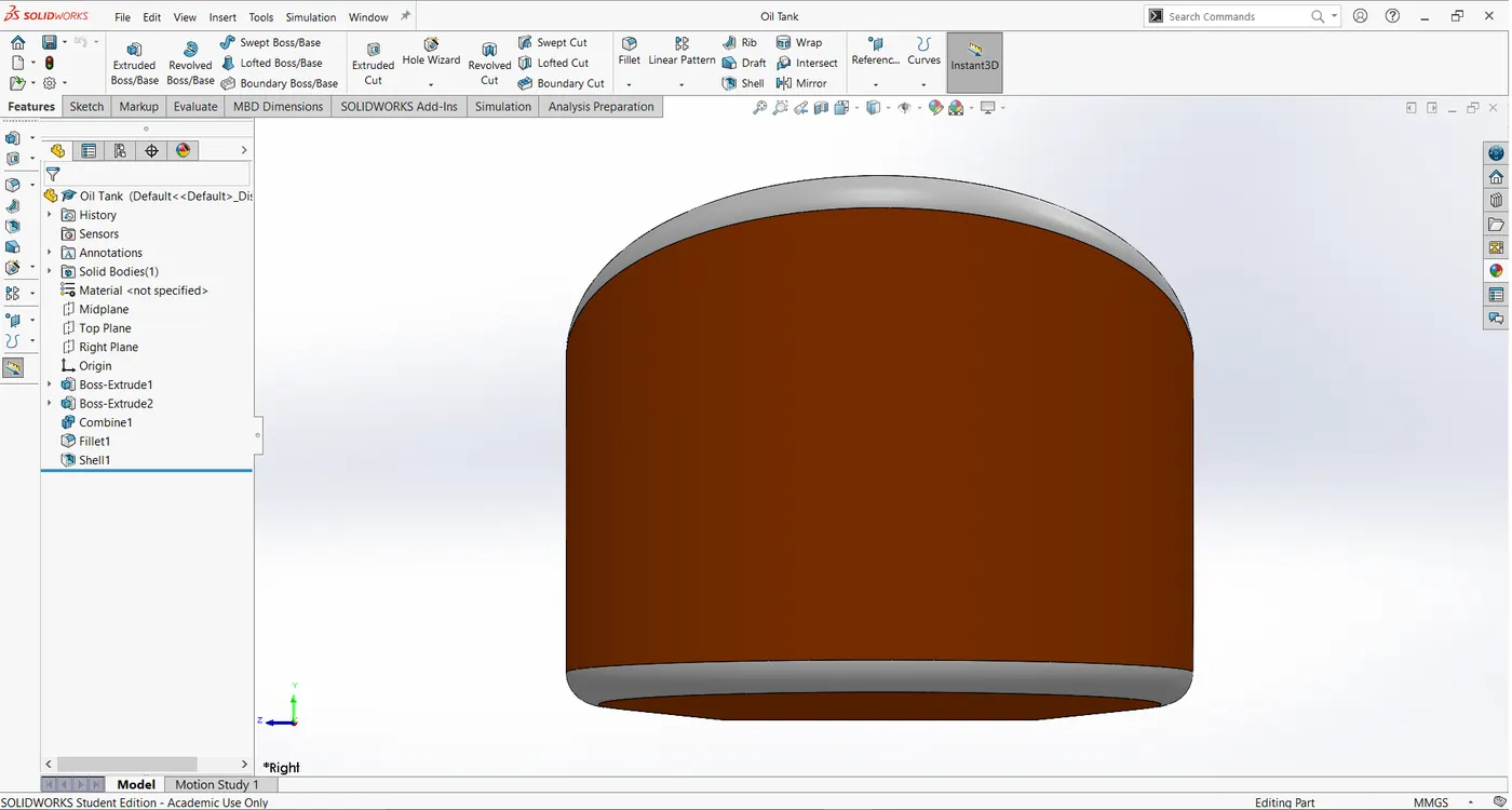
6. Oil Tank:
To store the oil for lubrication in the bike, Lubrication is necessary to avoid friction and give smooth function of rotating parts, so for lubrication purpose the oil tank is provided.
Features and tools used:
Line
Spline
Combine
Fillet
Shell
Trim
Smart Dimension
Boss extrude
Views:
Isometric view:
Front view:
Side view:
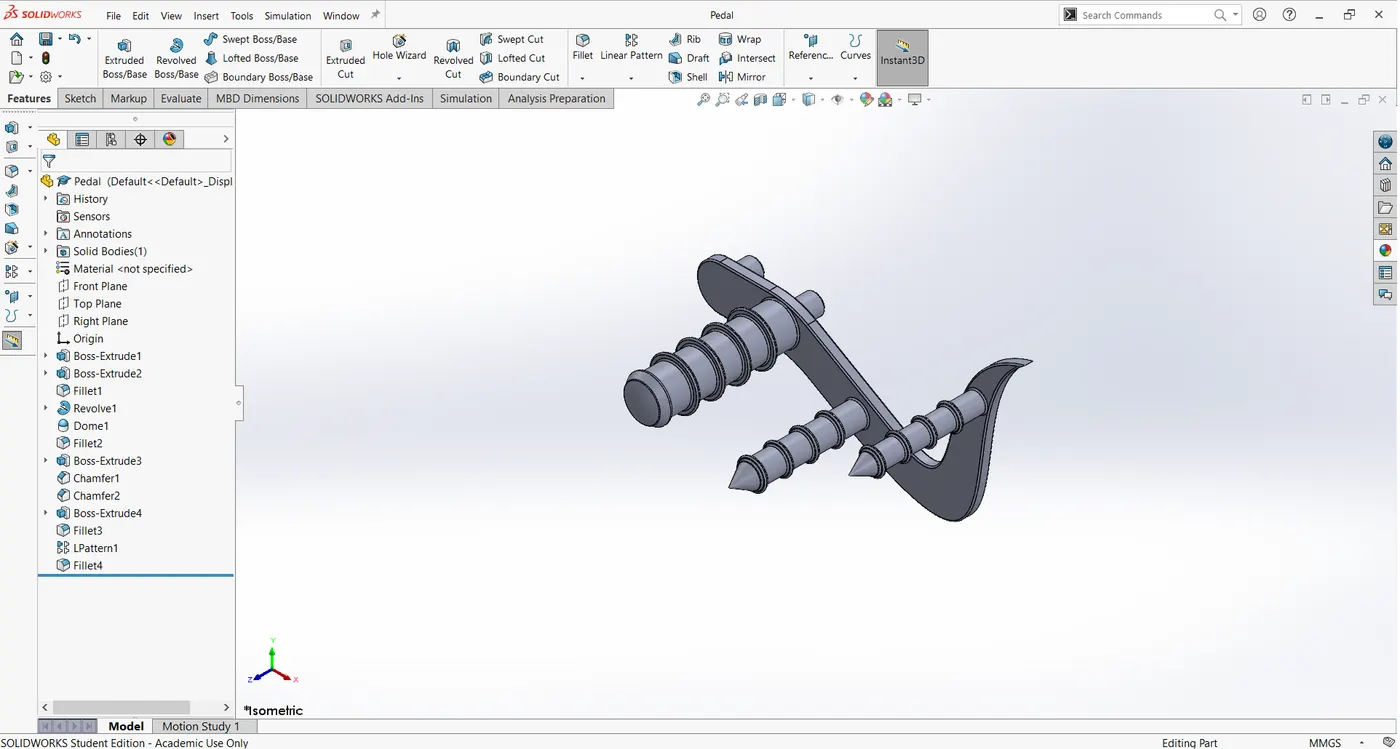
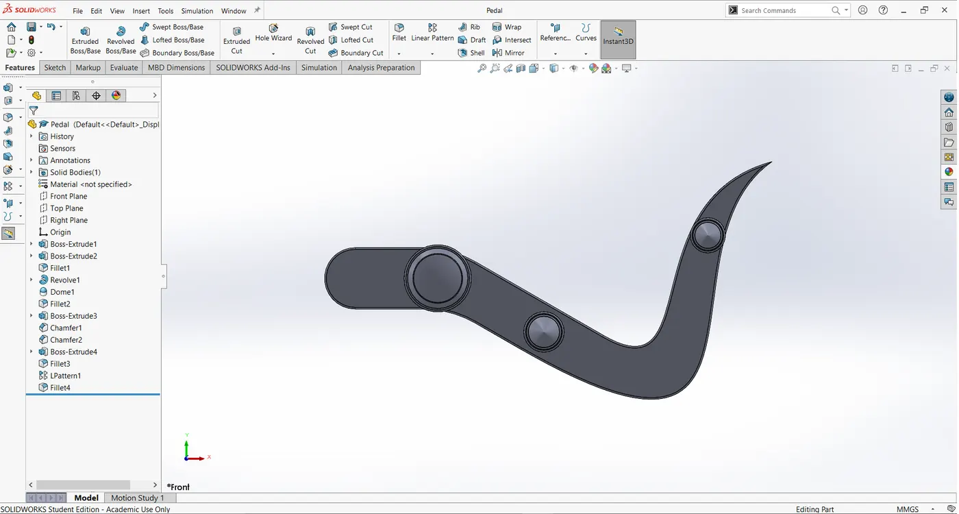
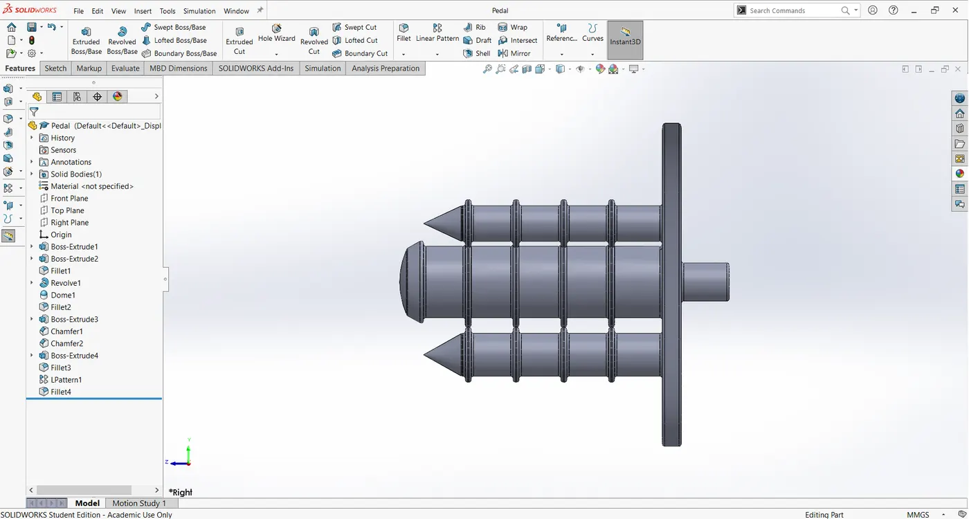
7. Pedal:
It is located on the sides of the bike its function is to shift gears for various speeds and act as a lever for brake to stop the bike.
Features and tools used:
Line
Revolve
Trim
Fillet
Linear pattern
Chamfer
Boss extrude
Dome
Views:
Isometric view:
Front view:
Side view:
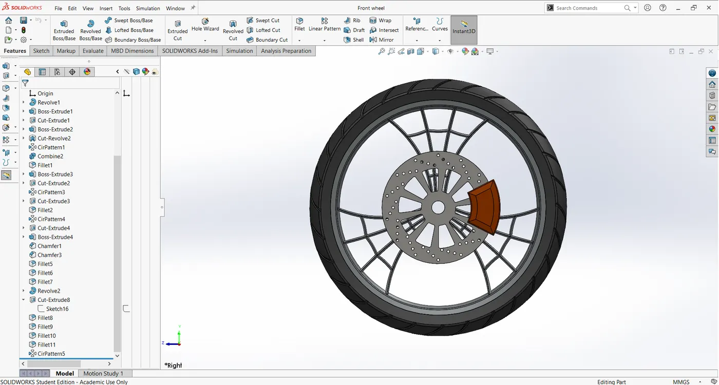
8. Front Wheel:
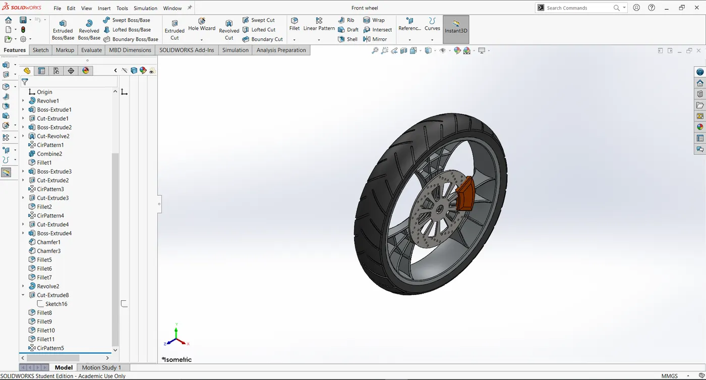
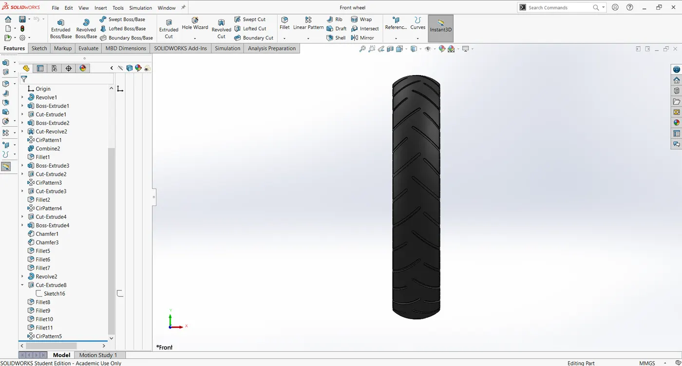
A circular object that revolves on an axle and is fixed below a vehicle or other object to enable it to move easily over the ground. It is located on the front side of the bike along with this wheel we have brake disc and calliper on it.
Features and tools used:
Line
Circle
Boss extrude
Cut extrude
Cut revolve
Revolve
Circular pattern
Combine
Fillet
Chamfer
Views:
Isometric view:
Front view
Side view:
9. Rear Wheel:
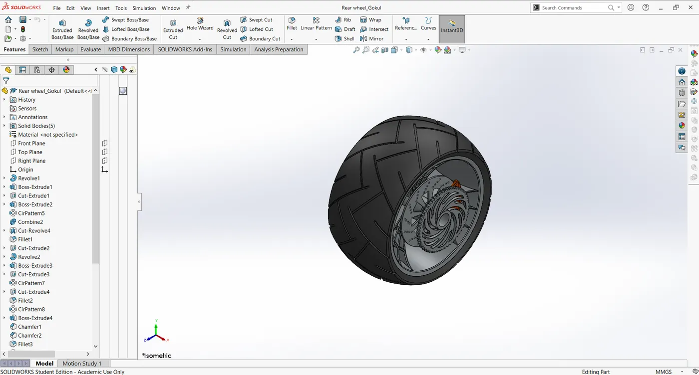
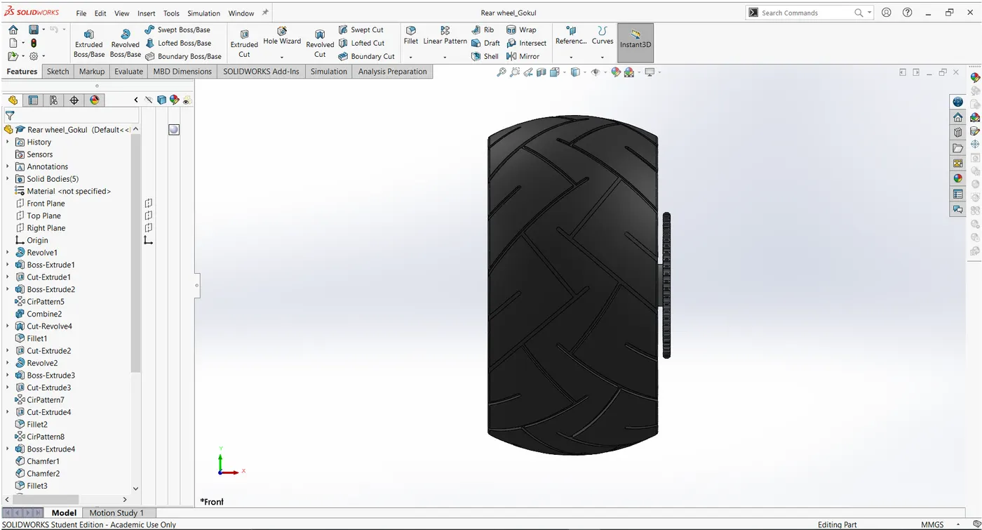
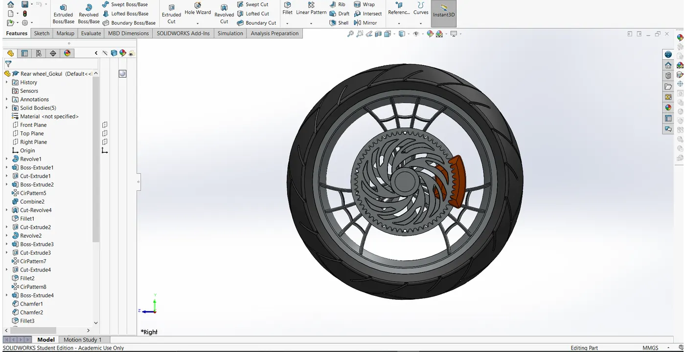
A circular object that revolves on an axle and is fixed below a vehicle or other object to enable it to move easily over the ground. It is located on the Rear side of the bike along with this wheel we have brake disc, Sprocket and calliper on it.
Features and tools used:
Line
Circle
Revolve
Boss extrude
Cut extrude
Circular pattern
Combine
Cut revolve
Fillet
Chamfer
Views:
Isometric view:
Front view:
Side view:
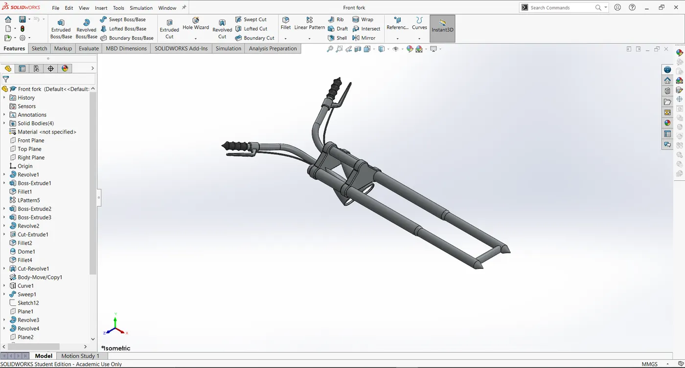
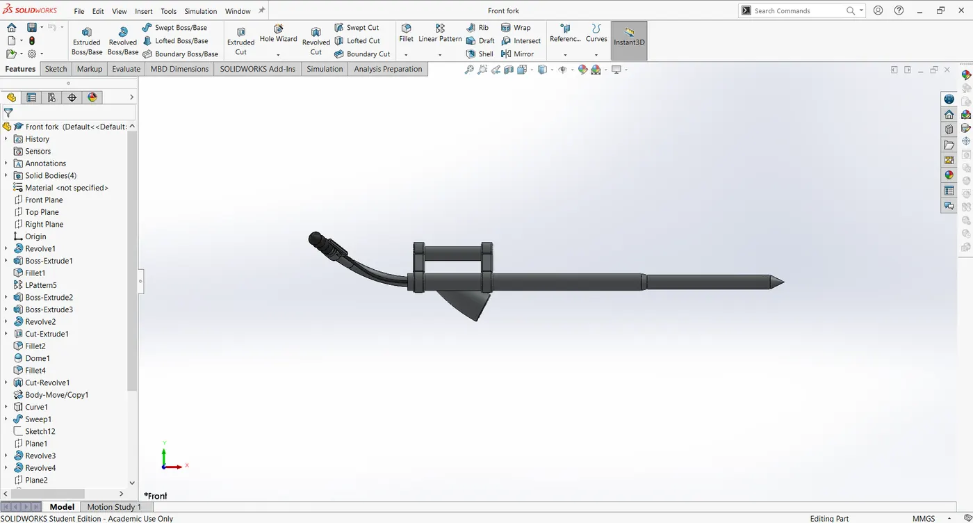
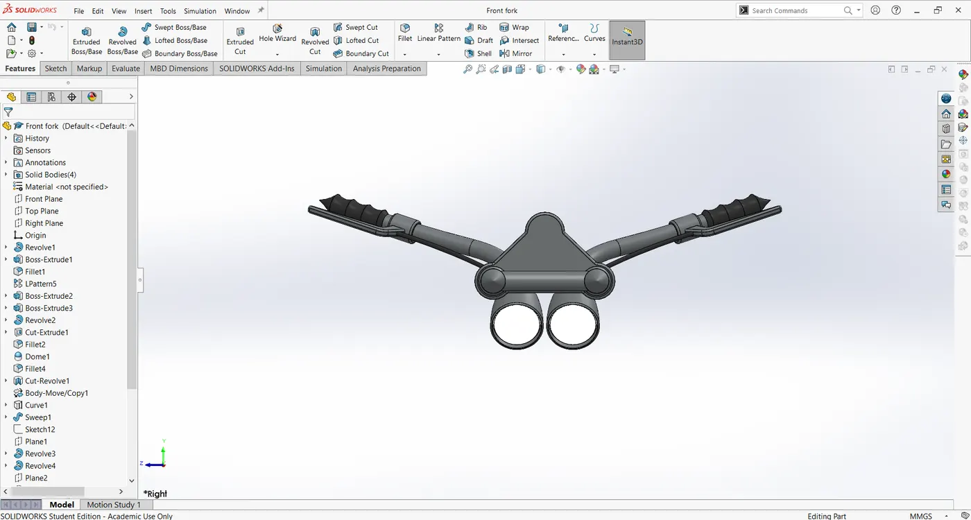
10. Front fork:
It acts as a handle of the bike to control the steering of the bike it is fitted on the chassis along with the front wheel, Head light and the front fender.
Features and tools used:
Line
Spline
Circle
Revolve
Boss extrude
Cut extrude
Fillet
Dome
Cut revolve
Projection of Curve
Sweep
Trim
Mirror
Combine
Views:
Isometric view:
Front view:
Side view:
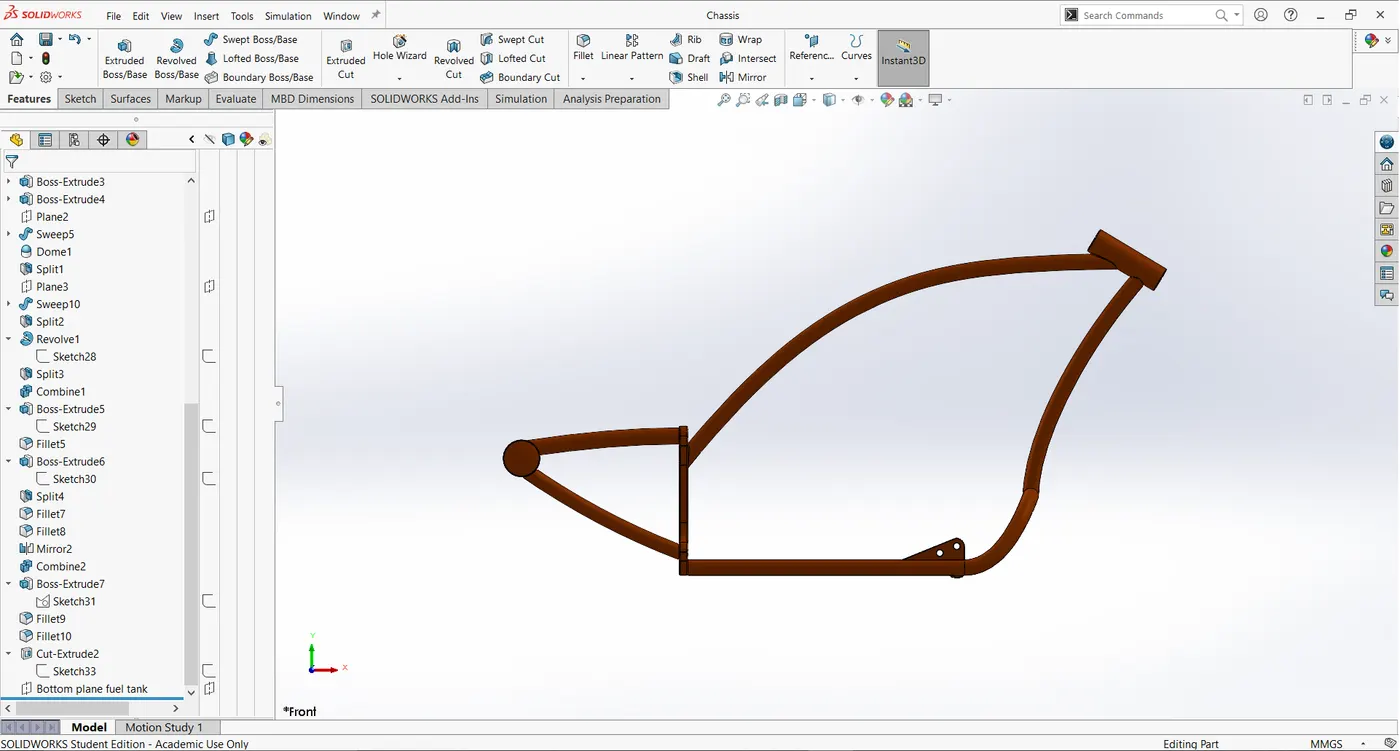
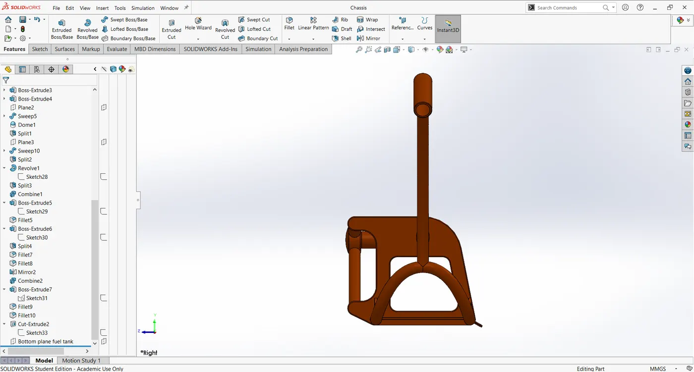
11.Chassis:
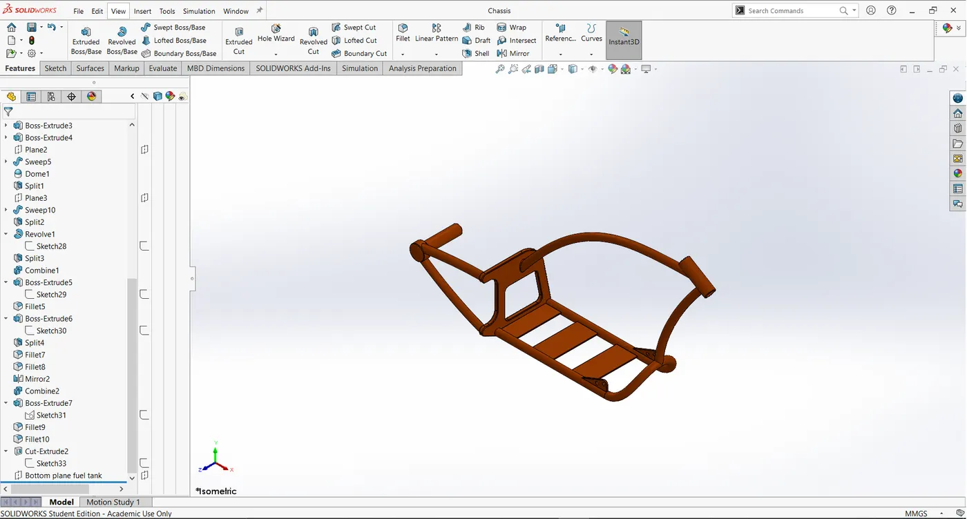
The skeleton of a motor vehicle consisting of a steel frame supported on springs that holds the body and motor.
Features and tools used:
Sketch (blueprint)
Line and spline
Projection curve
Sweep
Mirror
Boss extrude
Cut extrude
Chamfer
Fillet
Reference plane
Dome
Split
Trim
Combine
Views:
Isometric view:
Front view:
Side view:
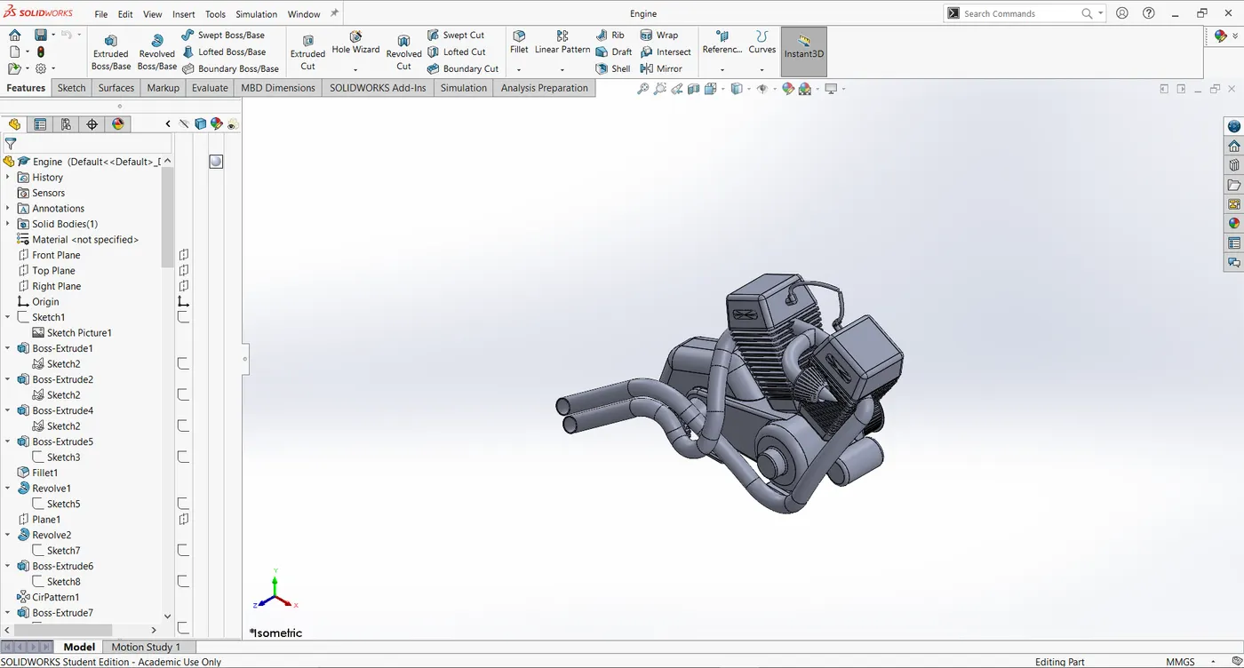
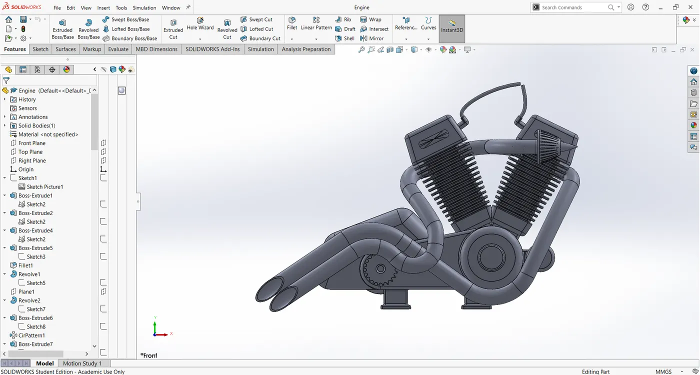
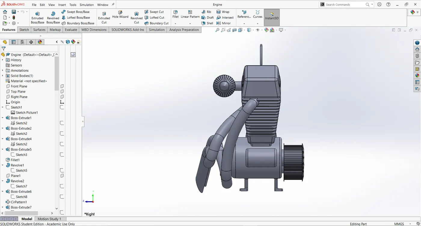
12. Engine:
It is an heart of an bike where heat energy is converted into mechanical energy.This is also known as Internal combustion engine(I.C Engine)
Features and tools used:
Line
Circle
Boss extrude
Fillet
Revolve
Reference planes
Circular pattern
Dome
Cut extrude
Chamfer
Fillet
Linear pattern
Split
Mirror
Revolve
Projection curve
Sweep
Composite Curve
Views:
Isometric view:
Front view:
Side view:
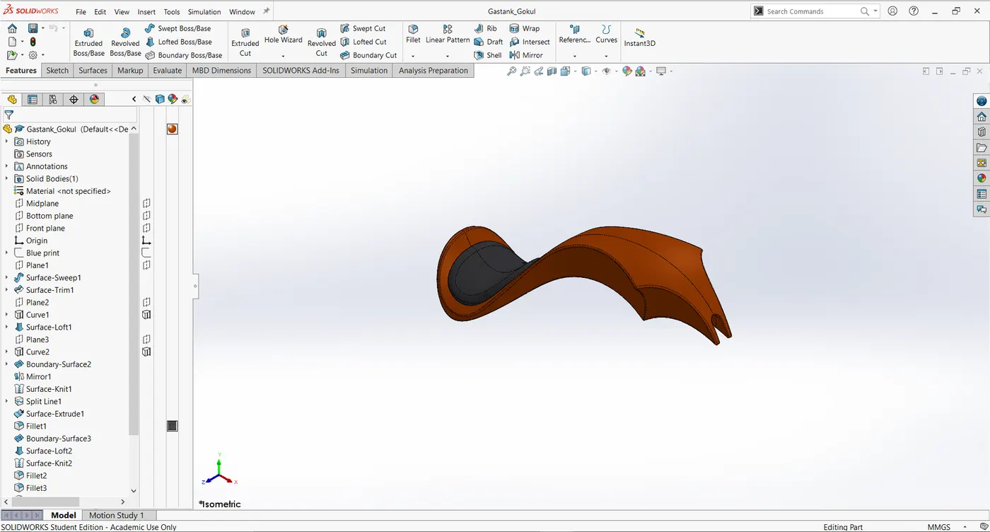
13. Gas tank:
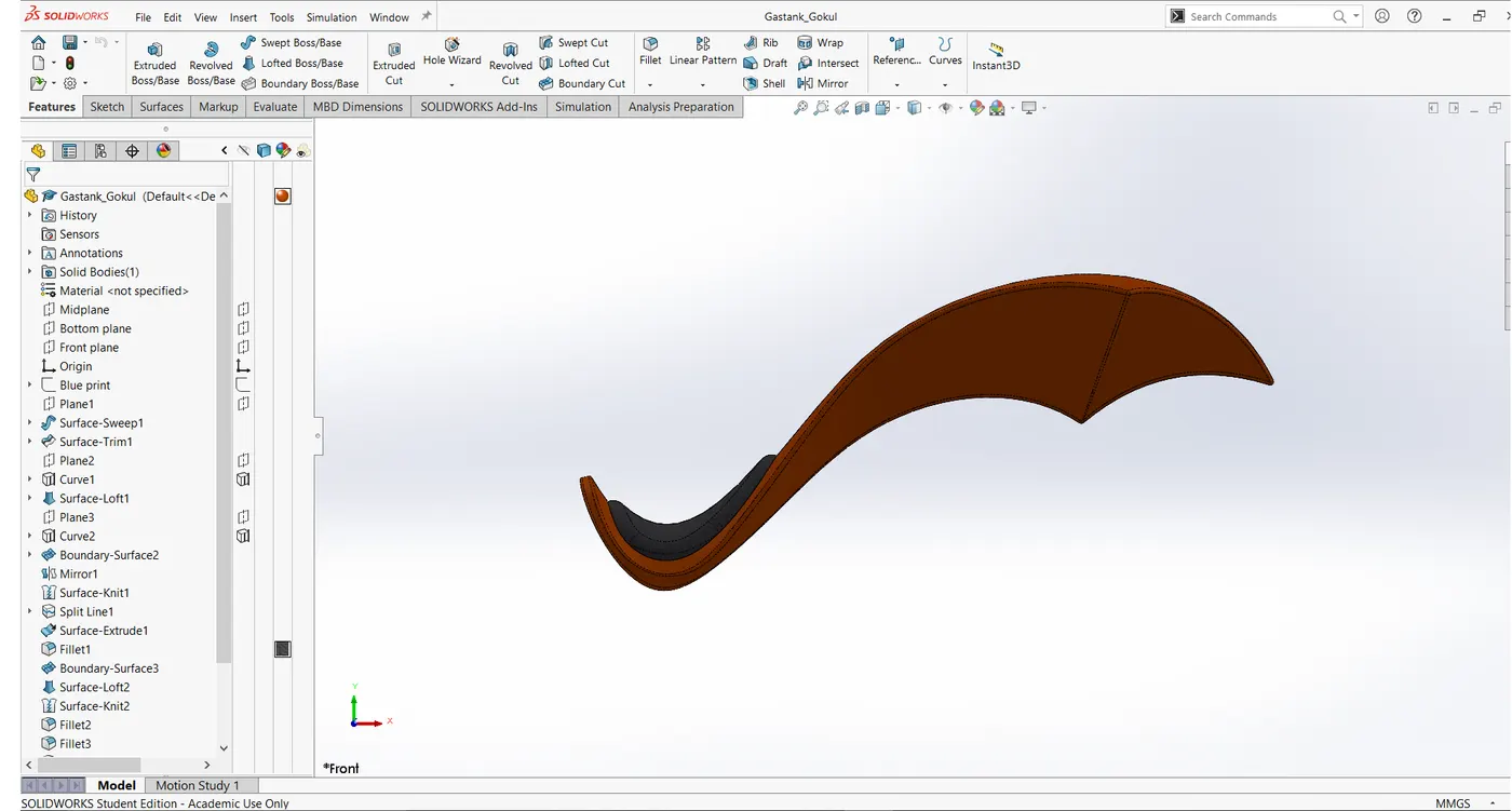
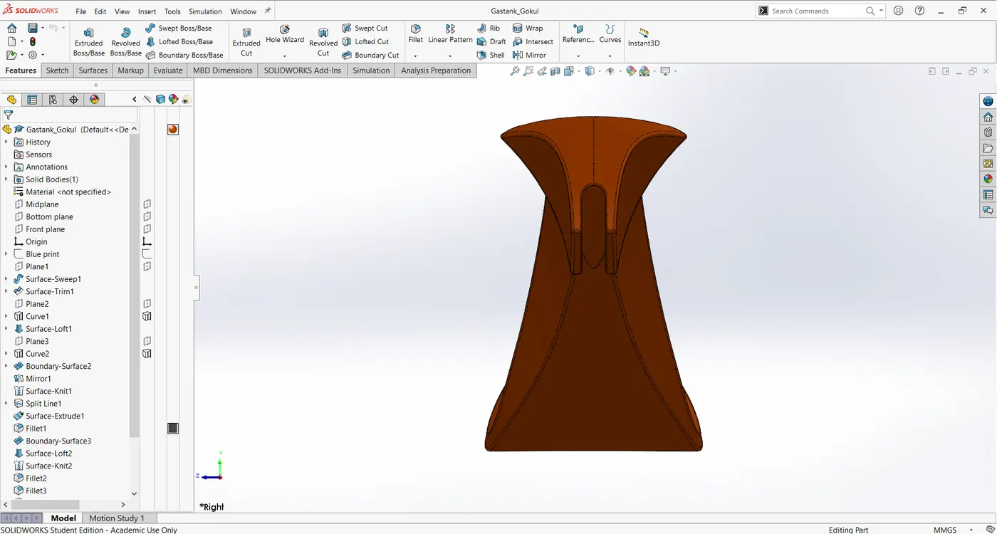
It is a tank which stores the gasoline to supply fuel to the engine for producing the power.
Features and tools used:
Sketch (Blue print)
Reference plane
Surface sweep
Surface trim
Projection curve
Surface loft
Boundary surface
Mirror
Surface Knit
Fillet
Sweep cut
Shell
Views:
Isometric view:
Front view:
Side view:
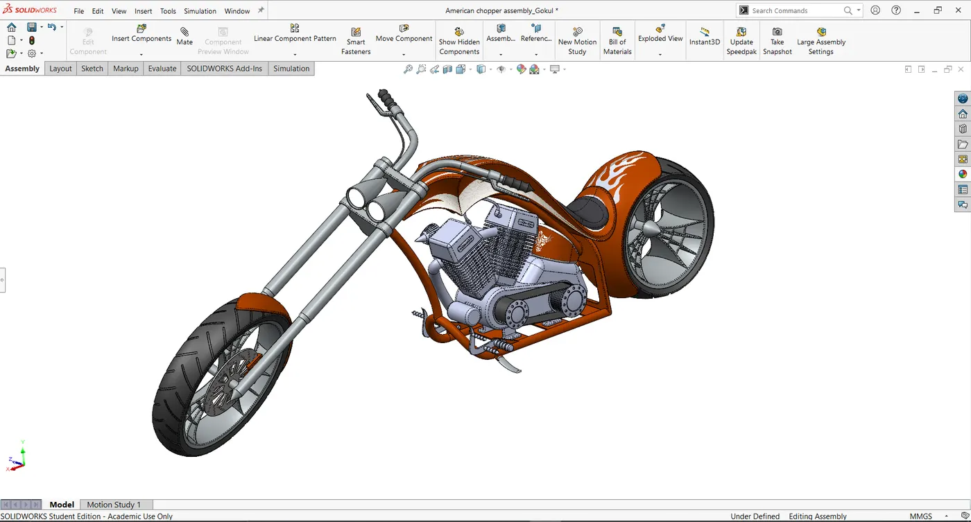
Assembly of the American chopper:
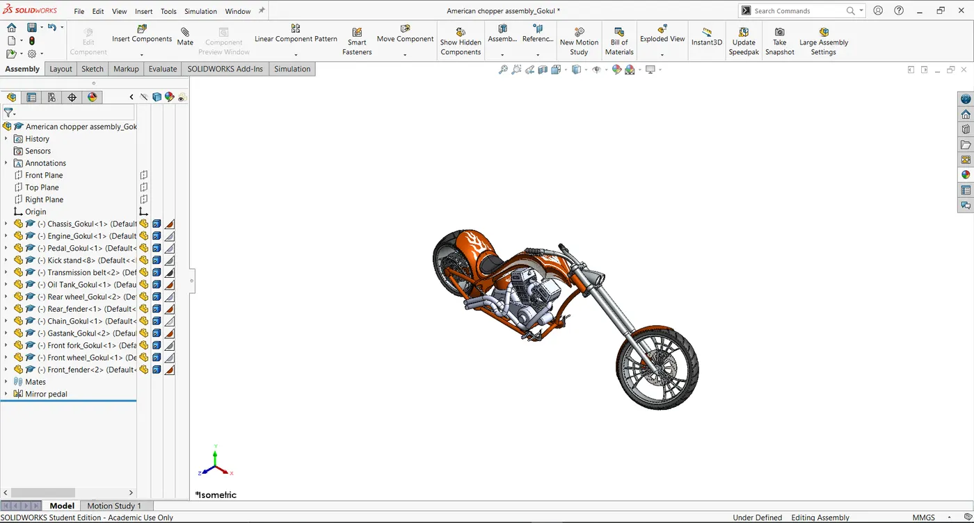
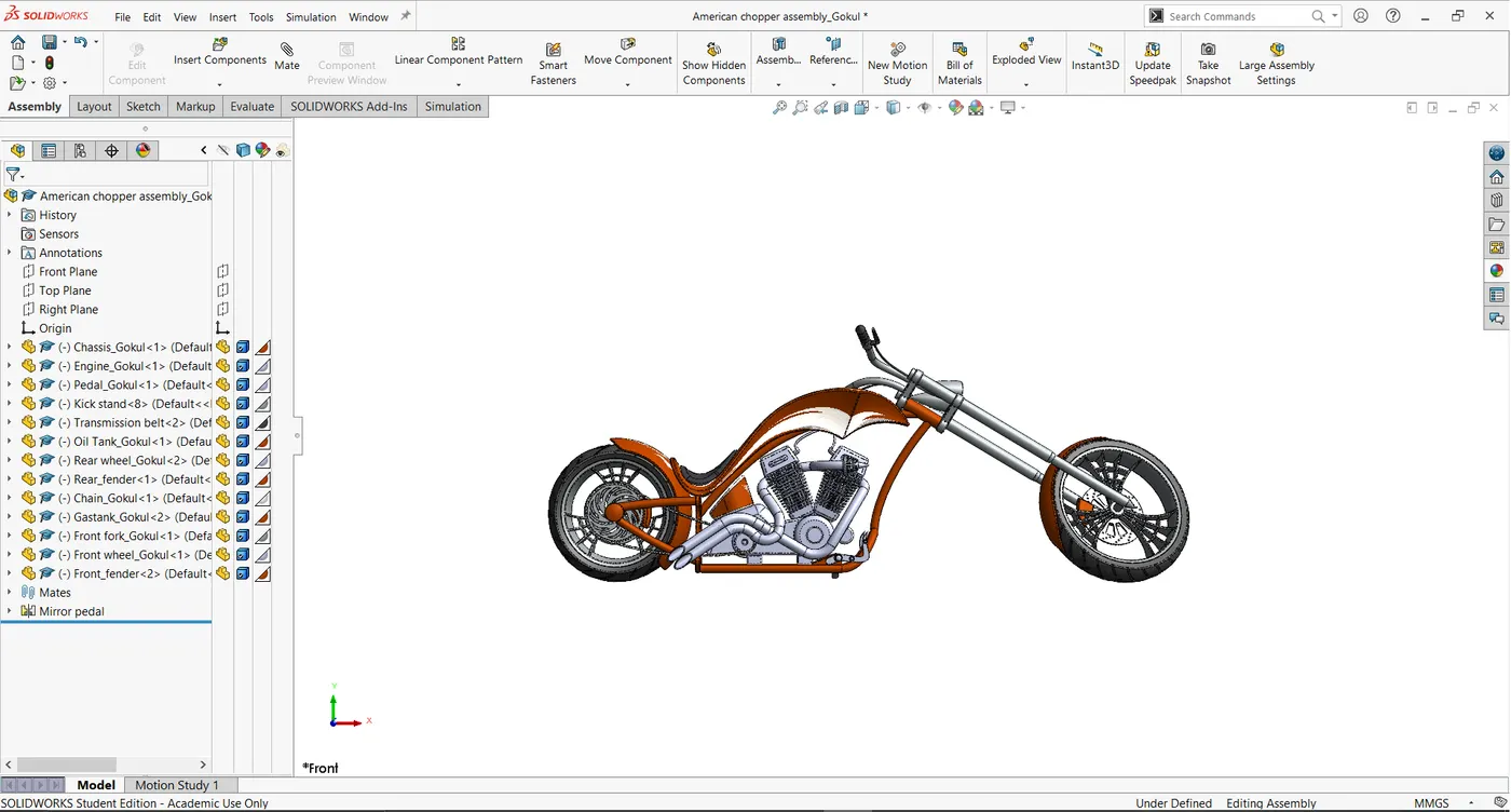
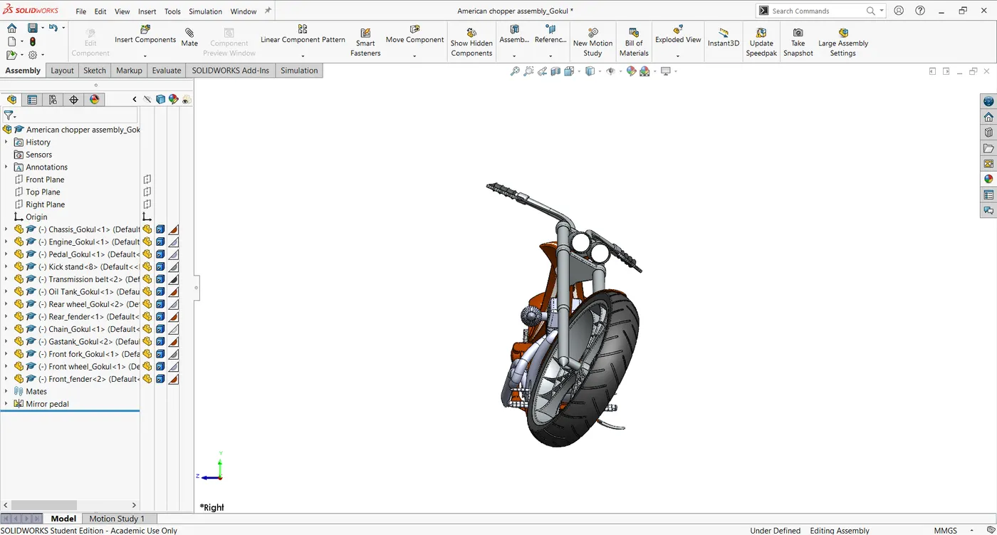
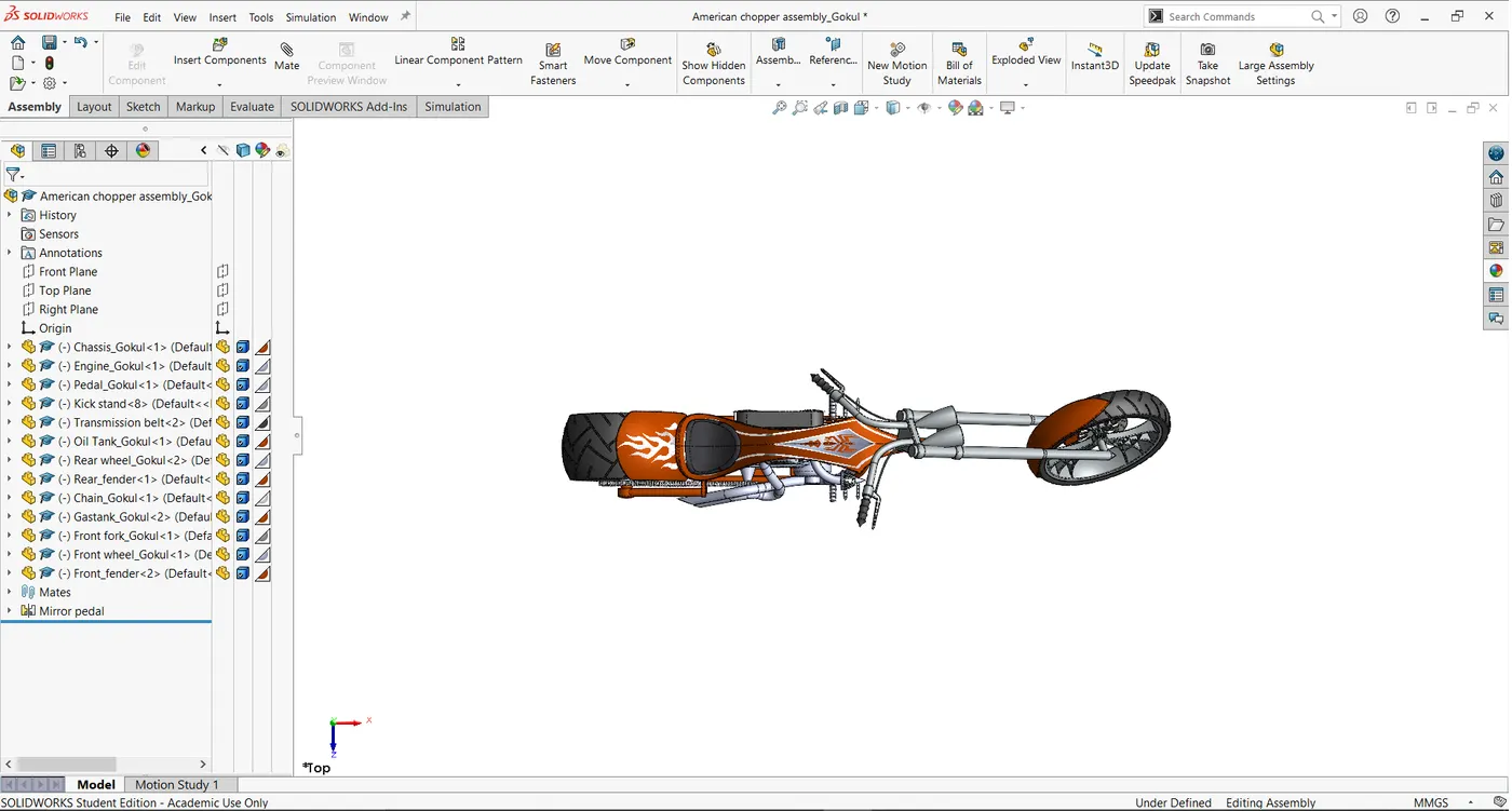
In this section we will be assembling the chopper with various individual parts and here we will be using different mating tools for each individual parts.
Features used:
- Mate
Mate:
It is an option with various mating features for eg joining of two cylindrical parts we use concentric feature the various mating feature listed below:
- Coincident
- Parallel
- Perpendicular
- Tangent
- Concentric, Etc.
Assembly views:
Isometric view:
Front view:
Side view:
Top view:
Camera view:
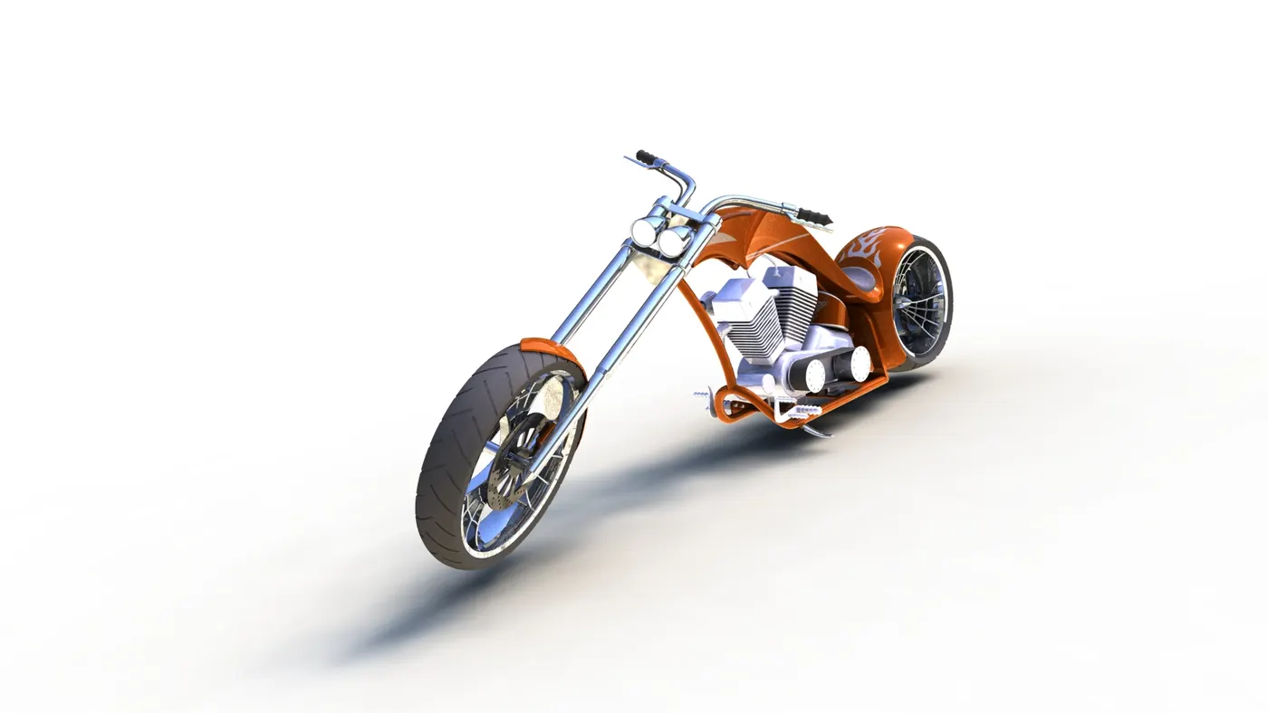
Photoview 360:
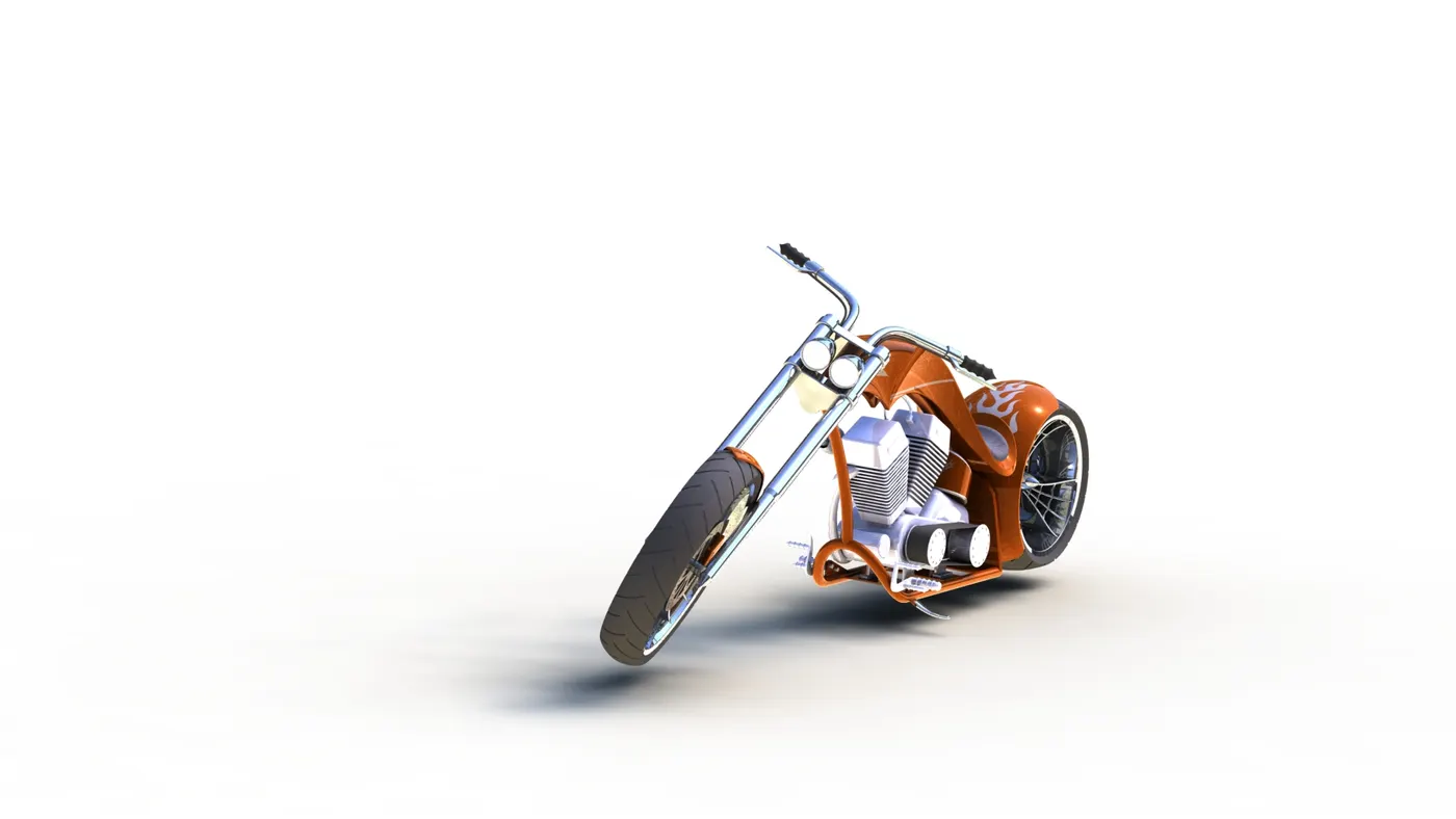
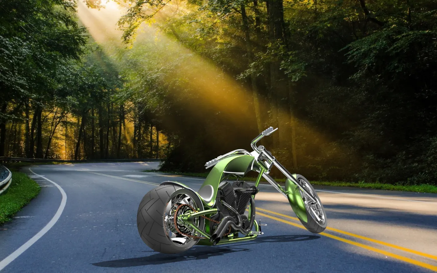
Solidwork Visualize (Realistic view with environment):
Normal view:
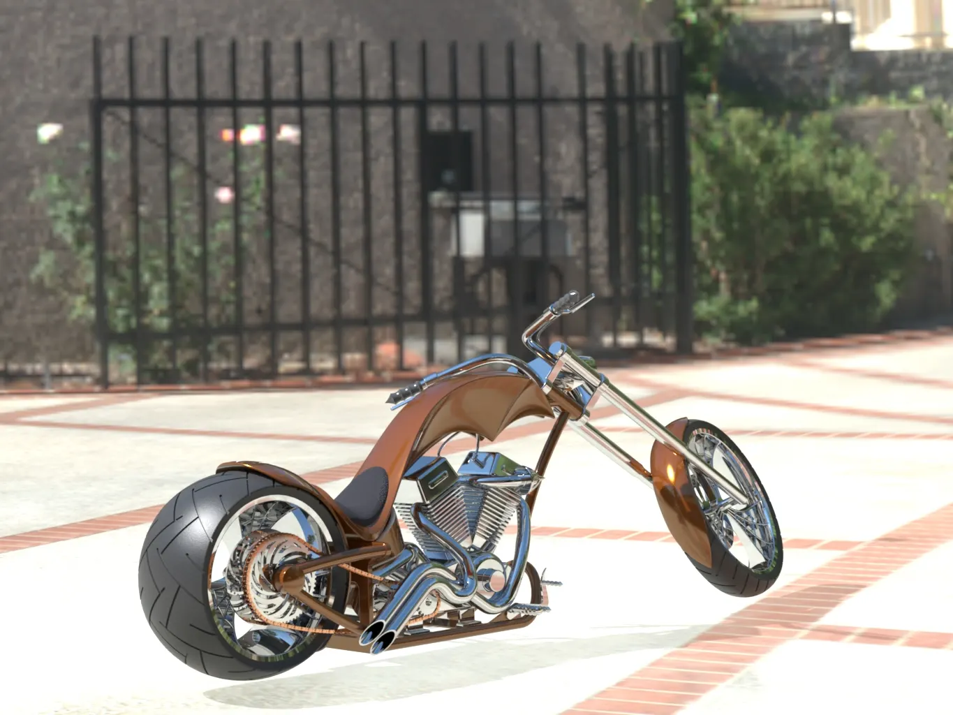
Isometric view:
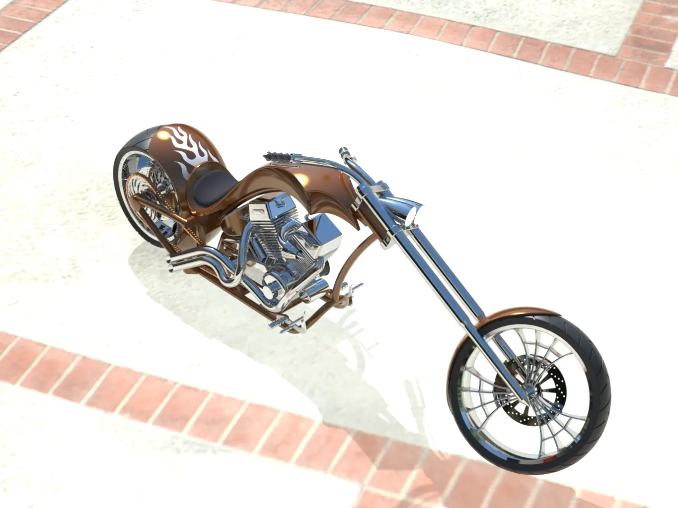
Front view:
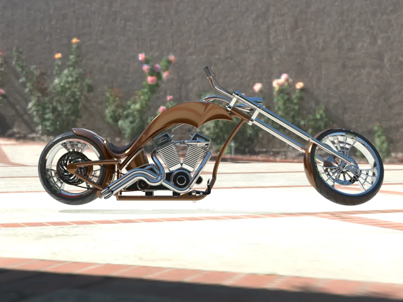
Side view:
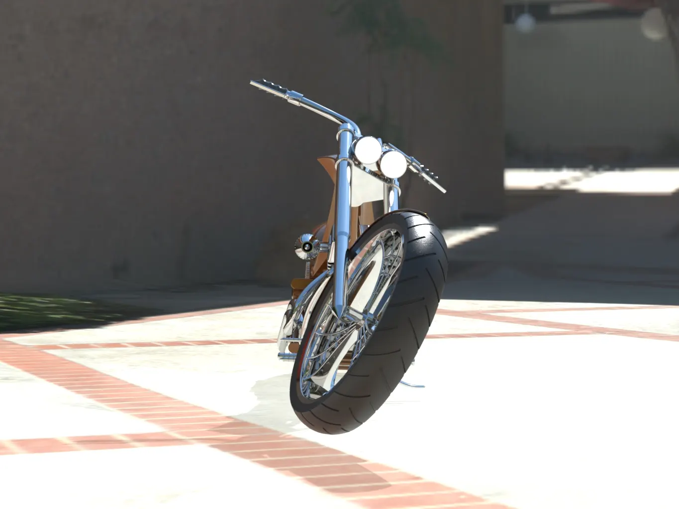
Top view:
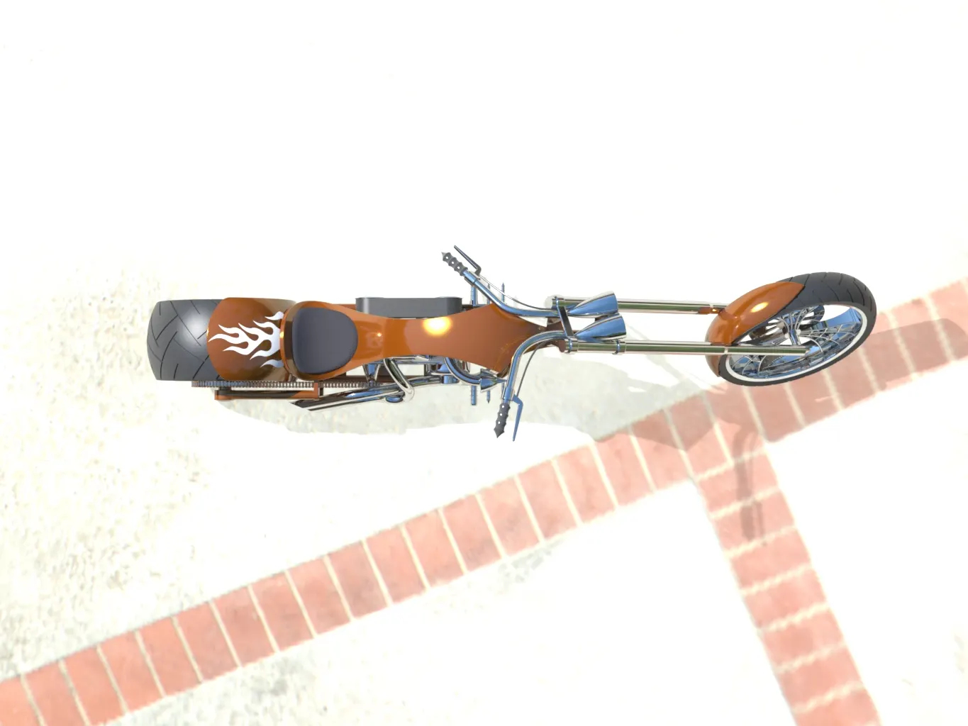
part rendering:
Engine:
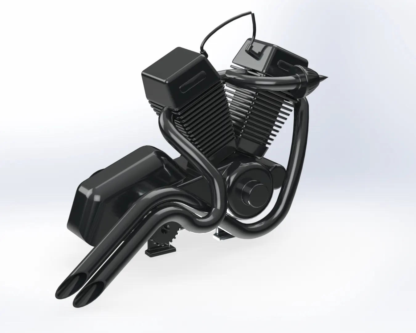
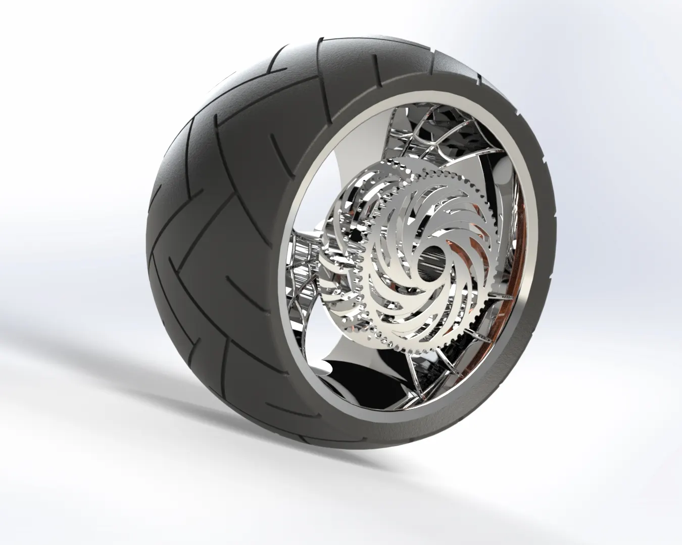
Front wheel:

Rear wheel:
Gas tank:
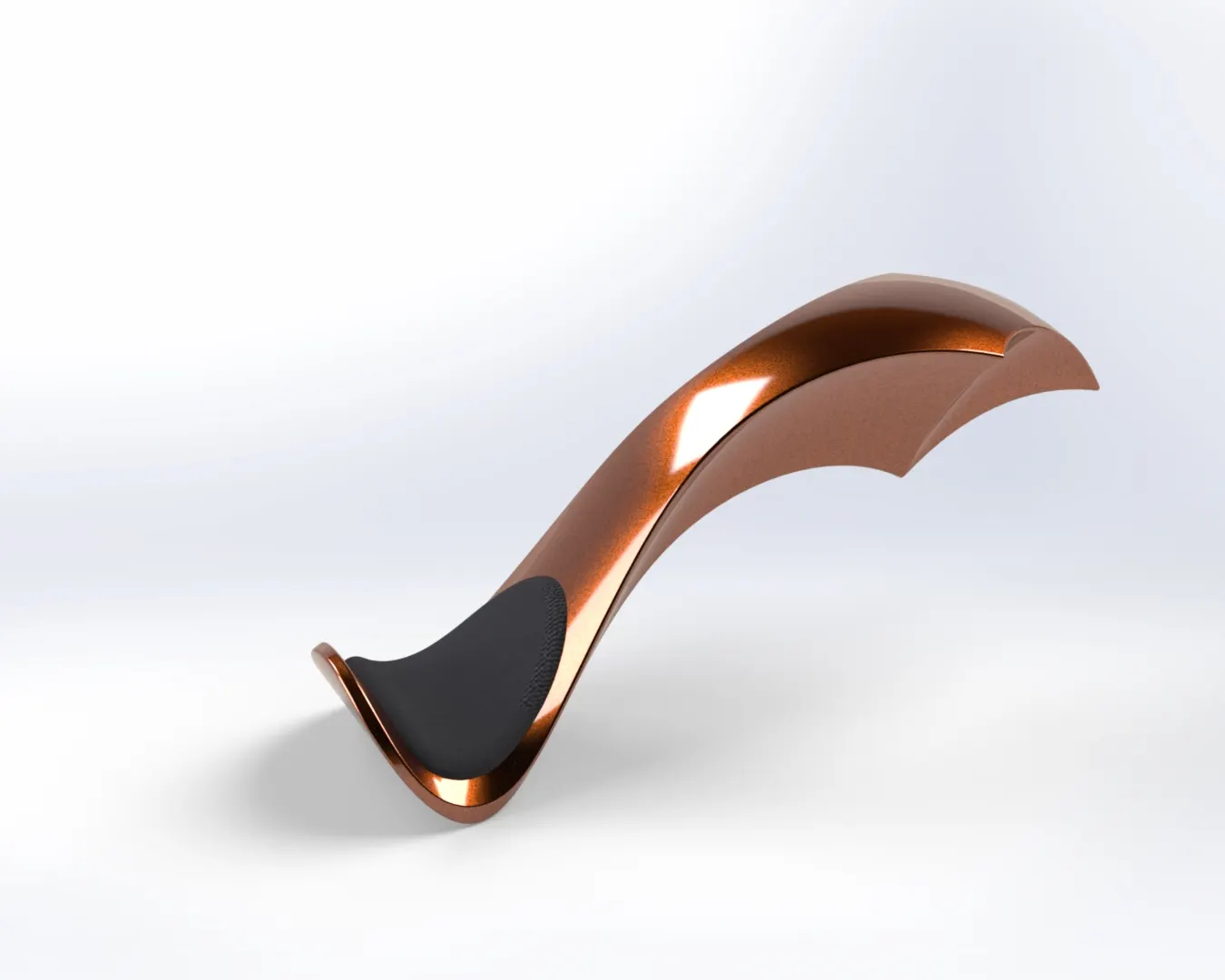
Conclusion:
- Finally the American chopper is designed using solidworks
- Learned about the sketch tools used in part designing and learned the mate feature used in the assemble section.
- Finally the photoview 360 and Realistic rendering gives the beautiful appearance to the sketch.
- Overall designing a part or object with proper dimensions and apperances from the start to end is learned.