Advanced Sheet Metal Design Using NX Cad Challenge_2_Box Assembly

OBJECTIVE:
- To create a box assembly on the Sheetmetal by using Siemens NX 11.
- Learning about the features and tools used in this design.
INTRODUCTION:
- Sheet metalis metal formed by an industrial process into thin, flat pieces. Sheet metal is one of the fundamental forms used in metalworking, and it can be cut and bent into a variety of shapes.
- For further details or reference:( https://en.wikipedia.org/wiki/Sheet_metal )
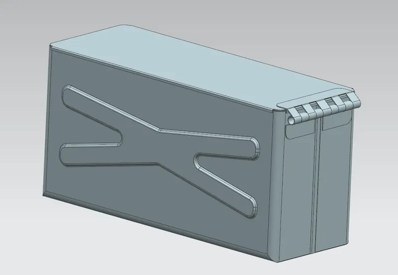
- In this box assembly we are going to design the outer cover, Hinge, Dimple, Bead, Etc.
DESIGN METHODOLOGY:
FEATURES AND TOOLS USED:
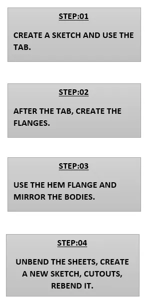
1) SKETCH: To create / Drawing the geometries, this is a basic and first tool for designing.
2) TAB: It is used to create a thickness of the sketched part. (MENU-INSERT-TAB)
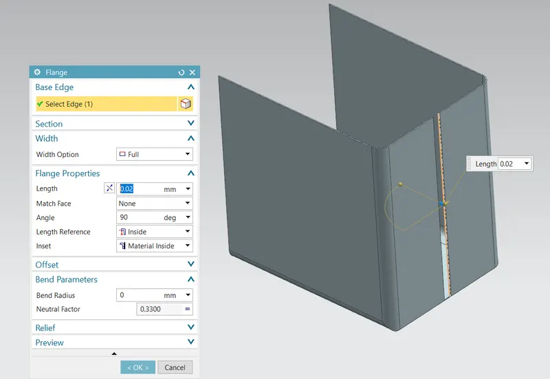
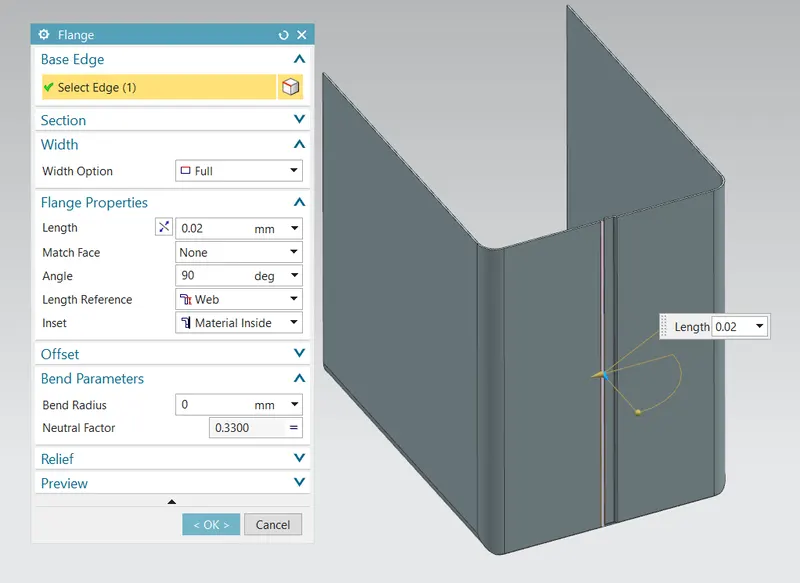
3) FLANGE : This tool is used to create bend region on the edges of the sheetmetal with bend radius,thickness,length. (MENU-INSERT-BEND-FLANGE)
4) NORMAL CUTOUT: This tool is used to cut out the selected regions. (MENU-INSERT-CUT-NORMAL CUTOUT)
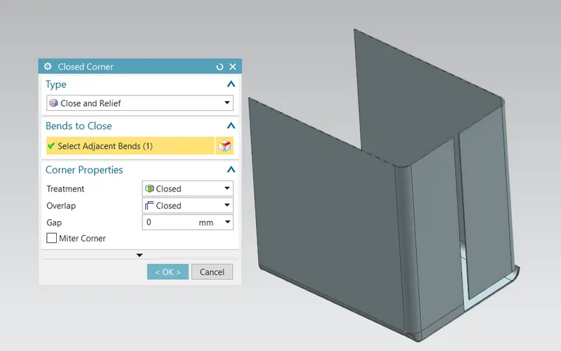
5) CLOSED CORNER : Its purpose is for closing the open edges and to have a closed bend edge.(MENU-INSERT-CORNER-CLOSED CORNER)
6) BEND/UNBEND: This feature is used to bend and unbend the sheetmetal.(MENU-INSERT-FORM-BEND/UNBEND)
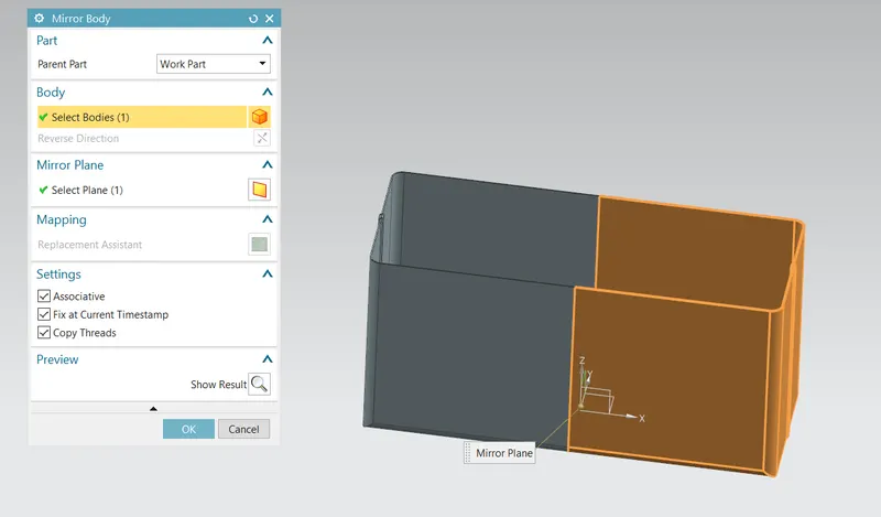
7) MIRROR BODY: This feature is used to mirror the bodies with respect to the plane or a line. (MENU-INSERT-ASSOCIATIVE COPY-MIRROR BODY)
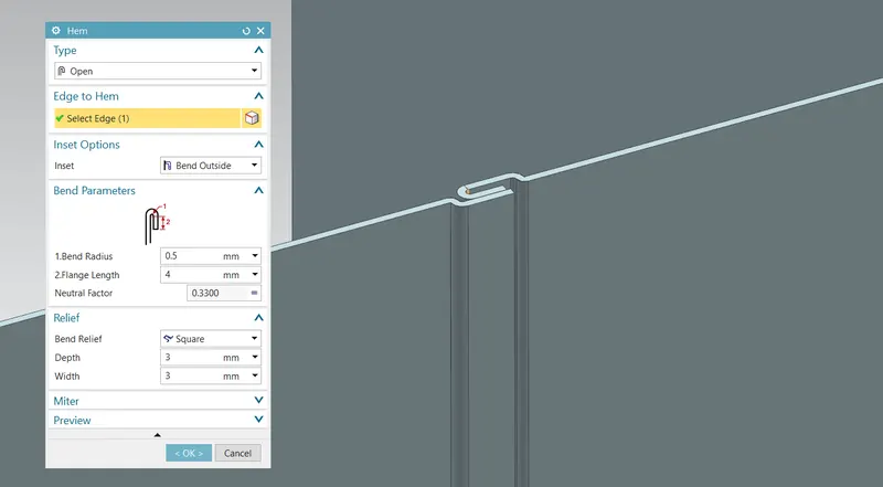
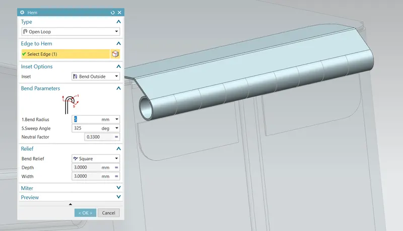
8) HEM FLANGE: It is used to create a bend region with some angle and radius. (MENU-INSERT-BEND-HEM FLANGE)
9) UNITE: This feature is used to make the two or more individual bodies into single body. (MENU-INSERT-COMBINE-UNITE)
10) BREAK CORNER: This feature is used to break the sharp corners on the sheetmetal. (MENU-INSERT-CORNER-BREAK CORNER)
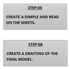
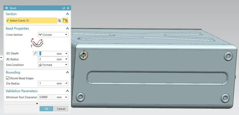
11) BEAD: It is used to create a punch tool on the surface of the sheetmetal with respect to the sketch. (MENU-INSERT-PUNCH-BEAD)
DESIGN METHODS:
Step 01: Creating a rectangluar sketch of dimension 200*150 and Tab the sketch with 1mm thickness.
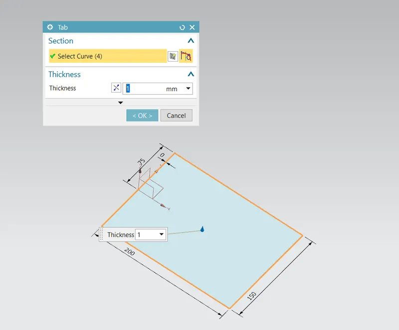
Step 02: Create a flange of length 200 (2 sides) and 70mm (2 sides)
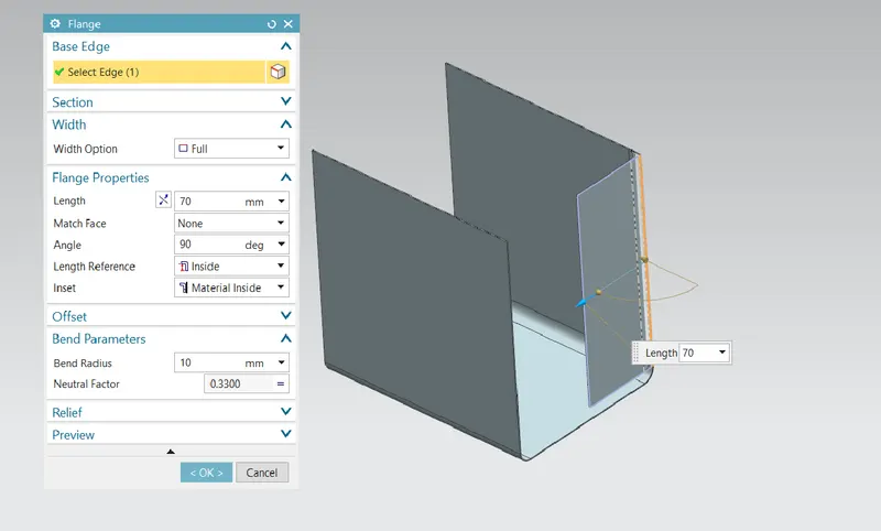
Step 03: create a close corner on the two edges.
Step 04: Create flange on the centre edge of the sheet.
Step 05: Create an another flange on the edge of the flange.
Step 06: Create a hem flange to have a hairpin bend on the edges.
Step 07: Select the mirror body option to have the same geometry on the other side and unite it to have a single body.
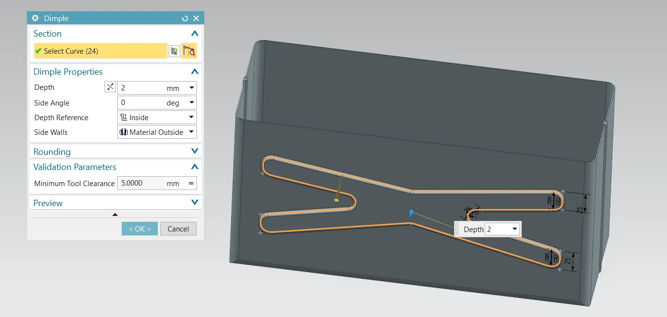
Step 08: Create an another sketch and use the dimple tool to have a punch formation on the sheet.
Step 09: Create an circle on the bottom of the box and use the bead option for creating the punch formation on it repeat this for other corners.
Step 10: To create a hinge draw a rectangular block on the particular area, Tab it for 2mm thickness and bend the region for certain degrees and unbend it,After that create a cutout tool and rebend it.
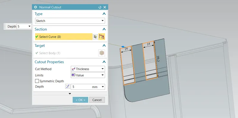
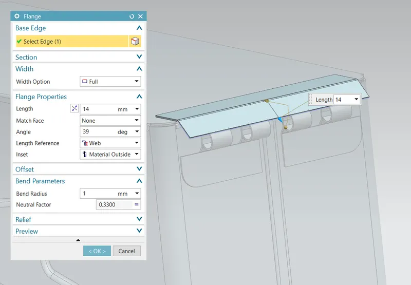
Step 11: Create an datum plane of distance 203mm and rectangular sketch on the plane and Tab it for 1 mm thick and provide flange for 14mm length @39 deg.
Step12: Create a hem flange for the bend curve to get a Hinge.
Step 13: Repeat the above process for the below hing and provide the cutouts.
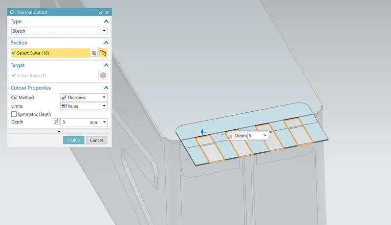
Step 14:The box assembly is finished.
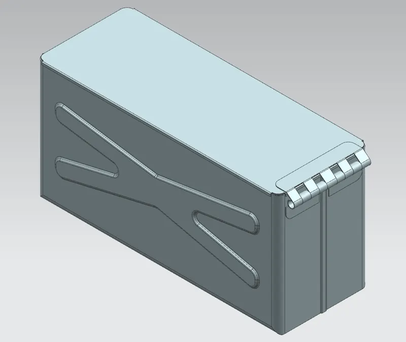
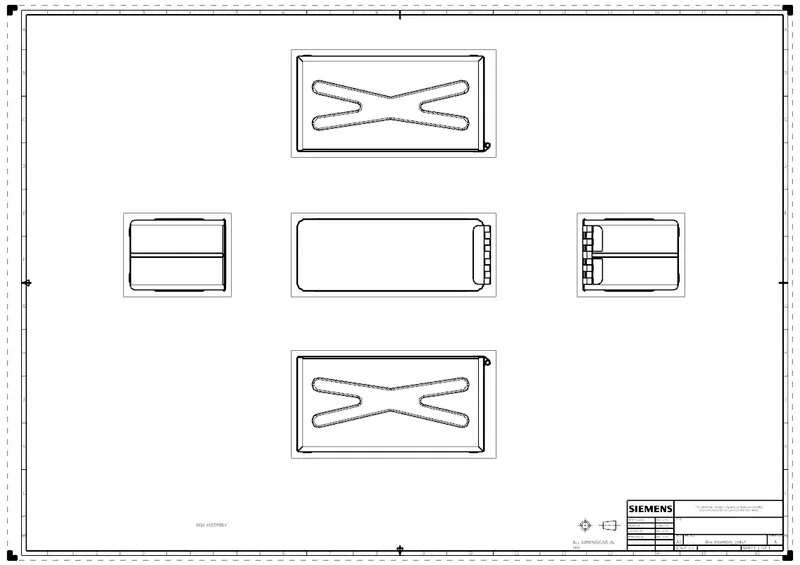
Views:
1) Top view:
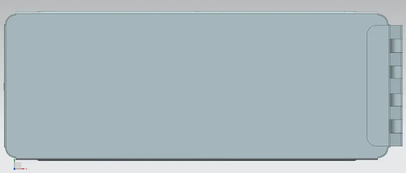
2) Side view:
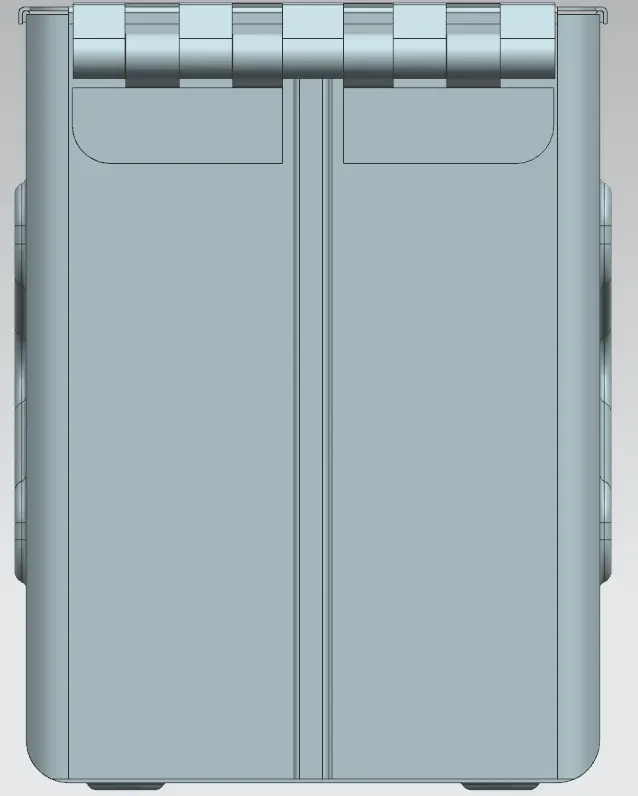
3) Front view:
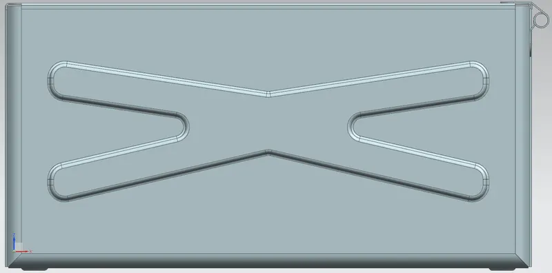
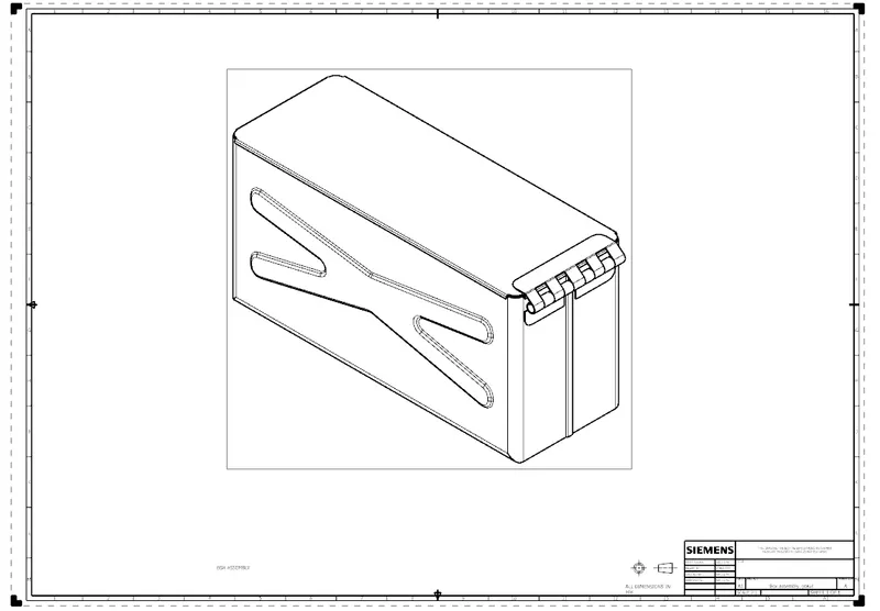
4) Isometric view:
Drafting:
CONCLUSION:
- FINALLY THE BOX ASSEMBLY IS DESIGNED IN SHEETMETAL BY SIEMENS NX11.
- LEARNED ABOUT DESIGNING THE HINGES AND THE BOX STRUCTURES.
- DRAFTING THE MODEL WITH VARIOUS VIEWS AND ADDING DETAIL INFORMATION ON IT.