Week 9 - Project 1 - Door Applique Design with Engineering Features
DESIGN OF DOOR APPLIQUE
OBJETIVE: The main motive for us in this challenge is to create a solid door applique body from a given class A surface and to design B- side features such as locators and heat stakes. Draft analysis have to be carried out on both class Asurface and final solid body. A report has to be prepared by explaining all the features and peocedures and by attaching all the relevant images.
DRAFT ANALYSIS
DRAFT ANALYSIS
Draft analysis is a analysis which is performed on the objects or bodies in order to check the draft angle of various faces in a particular direction which is tooling direction.
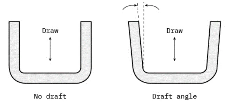
Every part like sheet metal parts which are generated from a Press Tool or some forming tools, may be the plastic parts which generally come out from the plastic moulds and maybe the casting parts, all such kind of parts required some drafted face on the surfaces which are parallel to the tooling direction. If we don't provide drafts on the surface then it will stick to the mould surface and whenever the mould is in motion they will destroy the surfaces or also reduced the finishing of surfaces.
The Tooling Direction is basically the direction that the mold pulls apart. The mold is built in two separate pieces, basically. You have a Cavity side and you have the Core side. The Core pulls apart from the Cavity and that's the Dyeline or the Tooling Direction.
And the axis which represents the tooling direction is called tooling axis and selection of this is axis is a crucial step while performing the draft analysis.
CLASS A SURFACE:
In automotive sector, a class A surface is any of a set of freeform surfaces of high efficiency and quality. Although, strictly, it is nothing more than saying the surfaces have curvature and tangency alignment – to ideal aesthetical reflection quality, many people interpret class A surfaces to have G2 (or even G3) curvature continuity to one another.
Class A surfacing is done using CAD applications. Class A surface modellers are also called "digital sculptors" in the industry. Industrial designers develop their design styling through the A-Surface, the physical surface the end user can feel, touch, see etc.
In general CLASS A surfaces are crated using autodesk alias software.
CLASS B SURFACE: Class B surfaces are the secondary surfaces that you can see sometimes, but are less important, such as the inside of your glovebox, ash tray, etc.. These must be smooth and "error-free" as well, but are not held to the standards that class A surfaces are.
CLASS C SUFACE: The Class C finish allows more imperfections than Class A or B. Class C is often specified for interior surfaces not readily visible, surfaces that will be covered by another part when assembled, or surfaces which the Customer feels do not need to meet a high cosmetic finish.
HEAT STACKS: Heat staking also known as thermoplastic staking is the process of joining two dissimilar materials together. In heat staking we use local heating and cooling to raise the temperature of plastic components and allow plastic reforming to be carried out. This reforming can be used in a wide variety of applications.
The progressive melting of plasti under continuous pressure forms the head. When staking, the right combination of heat and pressure for the application is critical.
ADVANTAGES OF HEAT STACKING:
- Simplification of machinery
- Reduced cost of machinery
- Multiple fastening points
- Allows higher density of welds compared to hot air cold from or ultrasonic welding.
CREATION OF TOOLING AXIS
First let us observe te given class A surface properly and we will see is there any faces which creates problems while manufacturing. The below image shows us the given class A surface of door applique,
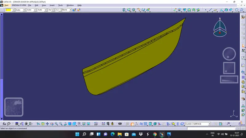
We can see that we have a large flat face and there is no other surface which will create an issue in this case. So we can create tooling axis at the centre of the flat plate.
1.Now first extract the flat face of class A surface
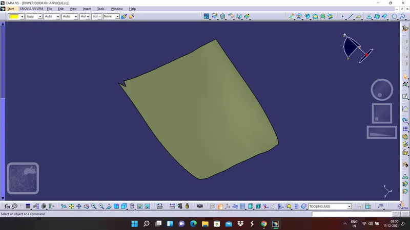
2. Now create point at the centre of the extracted surface and then create a line in Y direction and rename it as tooling axis and publish it if you want
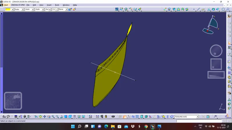
DRAFT ANALYSIS ON CLASS A SURFACE
1. Go to insert >> analysis>> feature draft analysis
2.Now click on the the compass and alogn it with the tooling axis which we have and the expanded colour code values of the draft analysis are given below in the picture
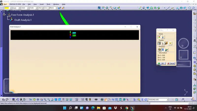
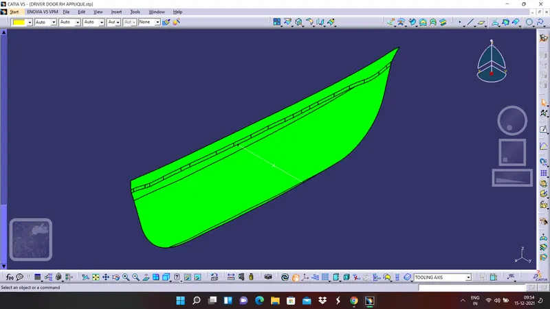
3. Now after aligning the compass with the tooling axis click on any face of the class A surface and observe the colour codes. Different views of the draft analysis of class A surface are given below
ISOMETRIC VIEW
FRONT VIEW
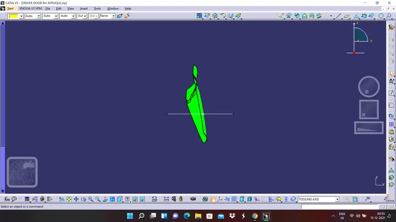
SIDE VIEW
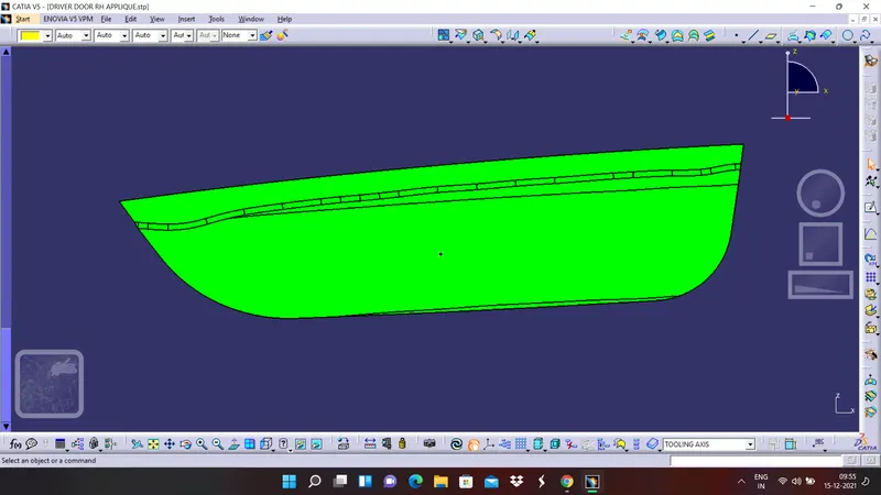
TOP VIEW
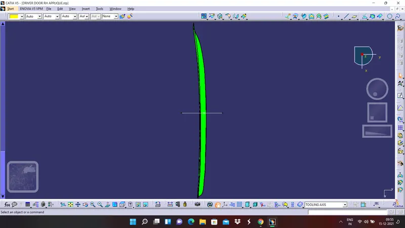
CREATION OF CLASS B SURFACE
1. Extract the surfaces of class B from class A surface
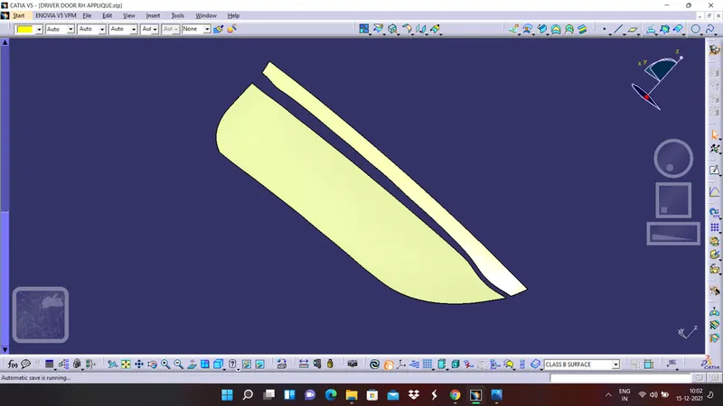
2. Untrim the extracted surfaces of class B
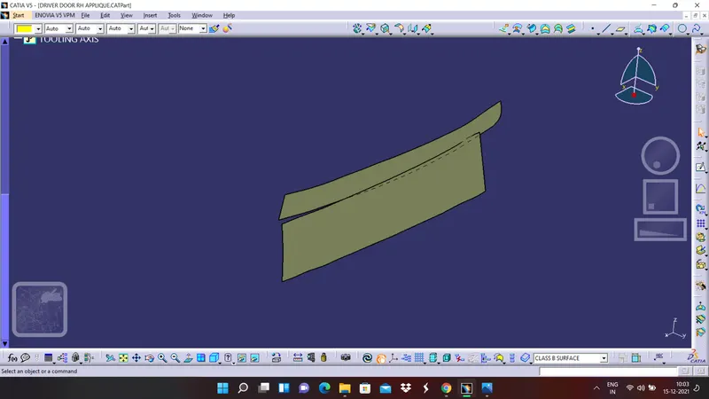
3. Extrapolated the untrimmed surfaces of the class B
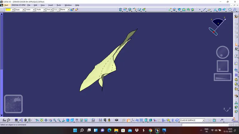
4. Offset the surfaces to 2.5 milli meters distance in a proper direction and the offsetted surfaces are showing in ornage colour in the below figure.
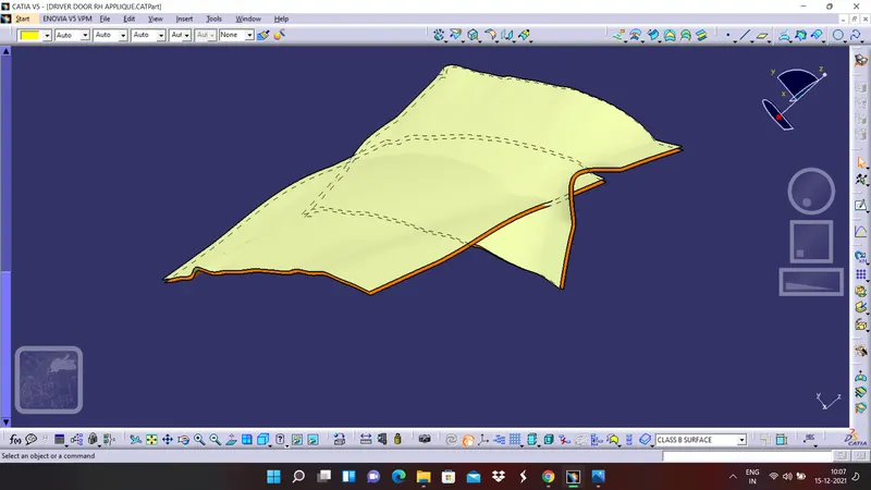
5. Trim the the two surfaces together
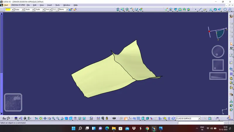
6. Finally apply the edge fillet with proper radius and rename it as a CLASS B surface and publish it
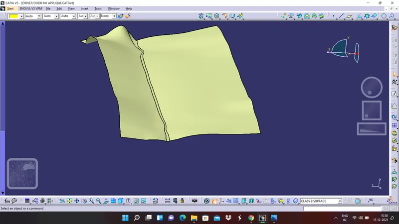
7.Apply a nice colour to the class B surface
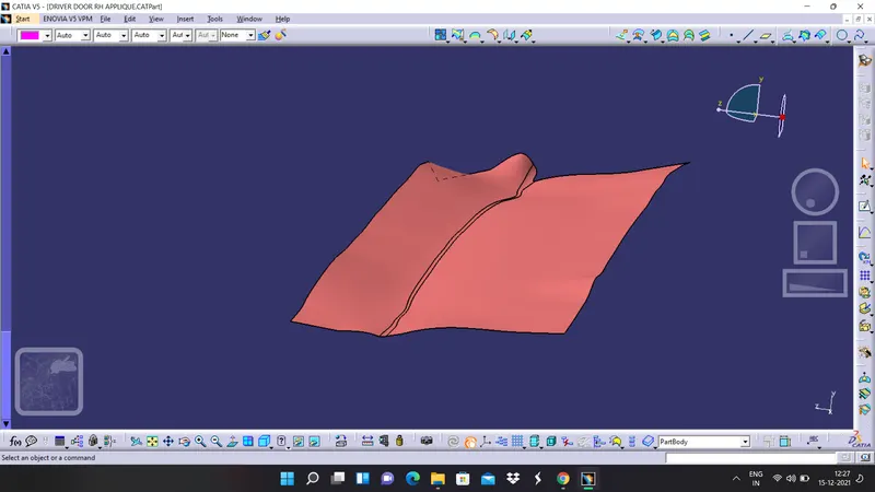
CREATION OF CLASS C SURFACE
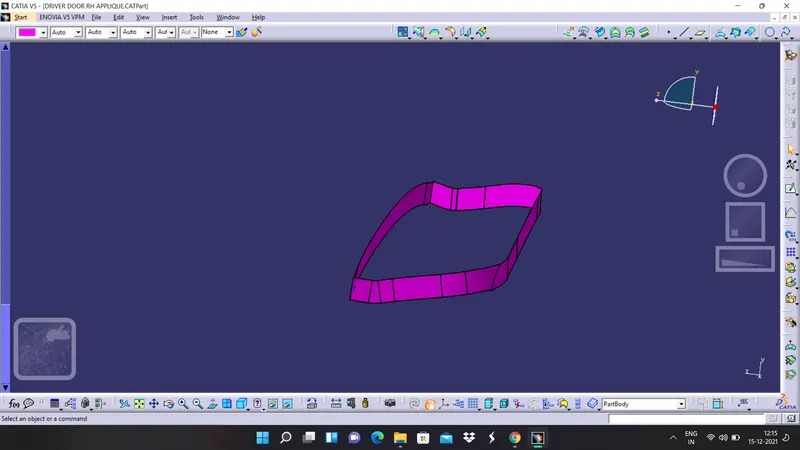
1. First create boundaries for small small portions
2. Try to sweep them seperately as one boundary each time
3. Extrapolate and trim the surfaces whereever required
4. Finally join the total surfaces with if required and name it as class C surfaces.
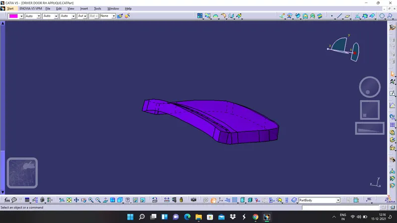
5. Join it with class A surface
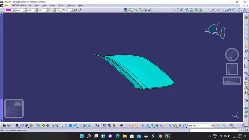
6. Finally trim it with class B surface and name it as final surface and give it a nice asthetic colour
DESIGN OF LOCATORS
1. Create a point at the centre of the counter part.
2. First create a plane by taking ZX plane as a reference and parallel to the point which we have created.
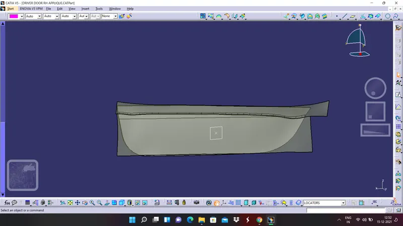
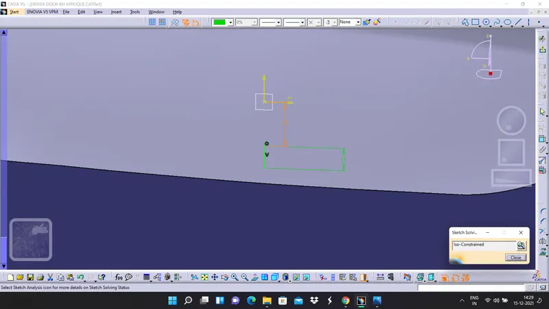
3. Draw a sketch on the plane which we have created and make sure the sketch is constrained properly
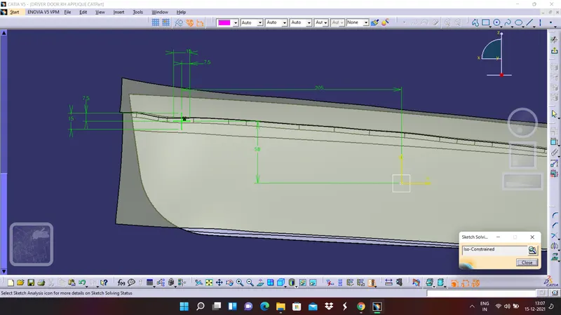
4. Create a pad for the sketch
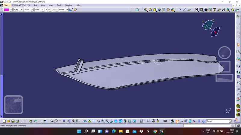
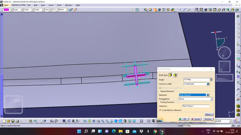
5. Apply draft to the pad
6. Apply chamfers to the edges
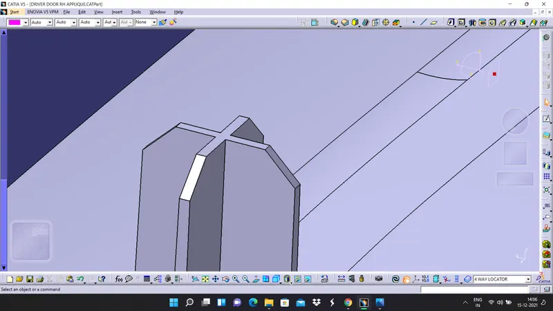
7. Aly fillets to the faces and make sure all the faces are filleted properly
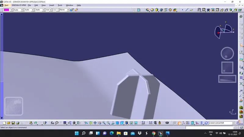
8. Copy paste the entire body of the locator and then translate the first locatore to another place.
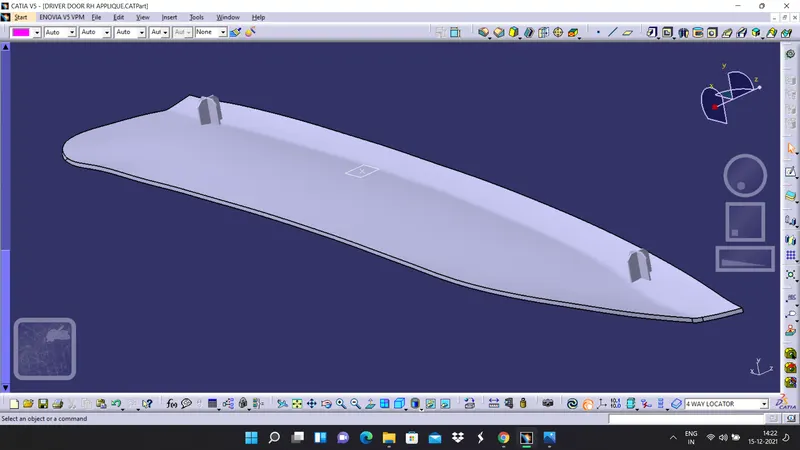
9. Now draw a sketch for two way locator and make sure the sketch is constrained properly
10. Create a pad for two way locator
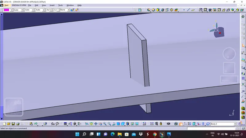
11. Provide draft for the surfaces
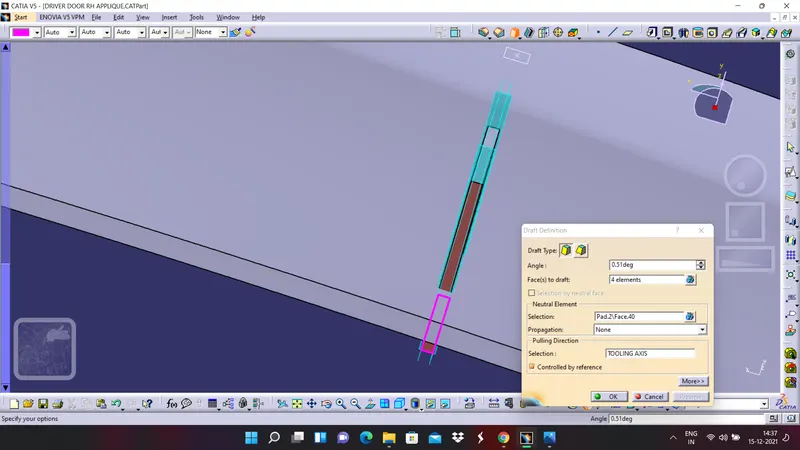
12. Provide an entry chamfer to the two way locator
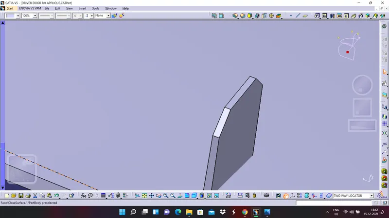
13. Apply edge fillet to the two way locator
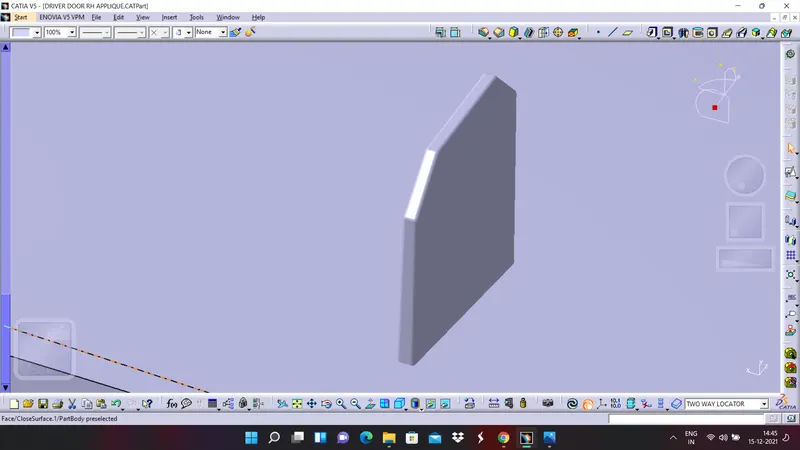
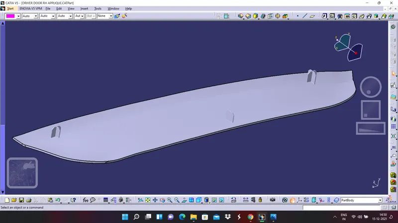
14. Now union trim the locators with the part body and apply edge fillets if needed
DESIGN OF HEAT STACKS
1. By using extract otions extracts the boundaries of class A surface
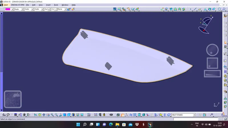
2. Extract the single surface of the body
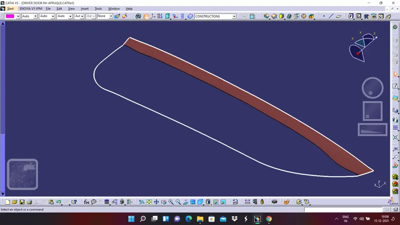
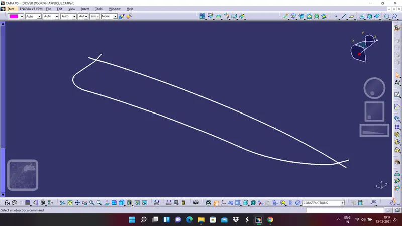
3. By using parallel curve command offset the curves inside the surface
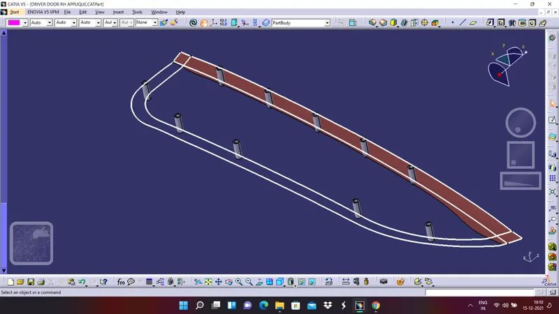
4. Now by using points and planes repetitive command create points on the parallel curves
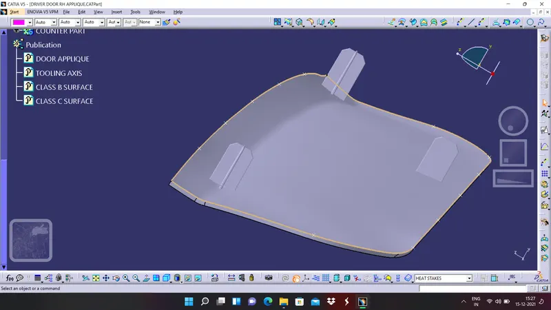
5. Now by using same plane and by taking one of the previously created point draw a sketch for heat stack
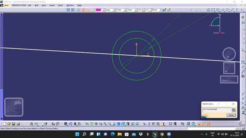
6. Now insert a body and pad it to a required distance and give adraft to it
7. Copy paste the heat stack body and translate it the every point that we have created on the parallel lines.
8. Insert another body and assemble all the heat stack bodies to it and trim it with the main body.
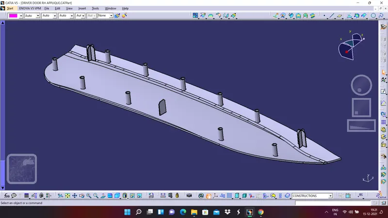
Now let us view the body in different view
ISOMETRIC VIEW
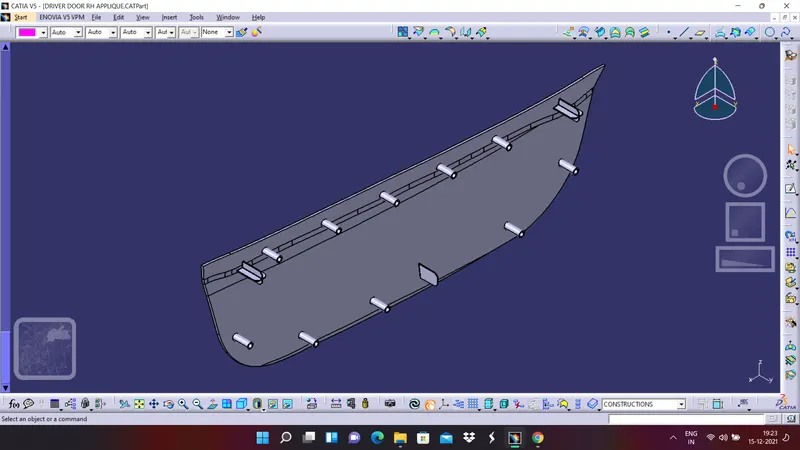
FRONT VIEW
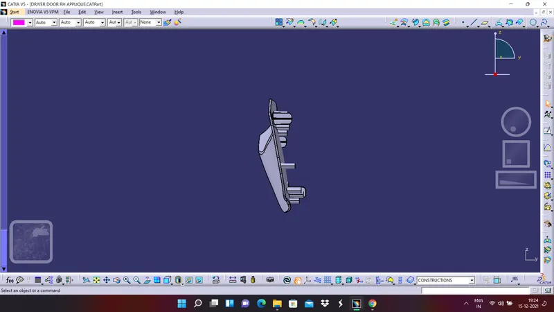
SIDE VIEW
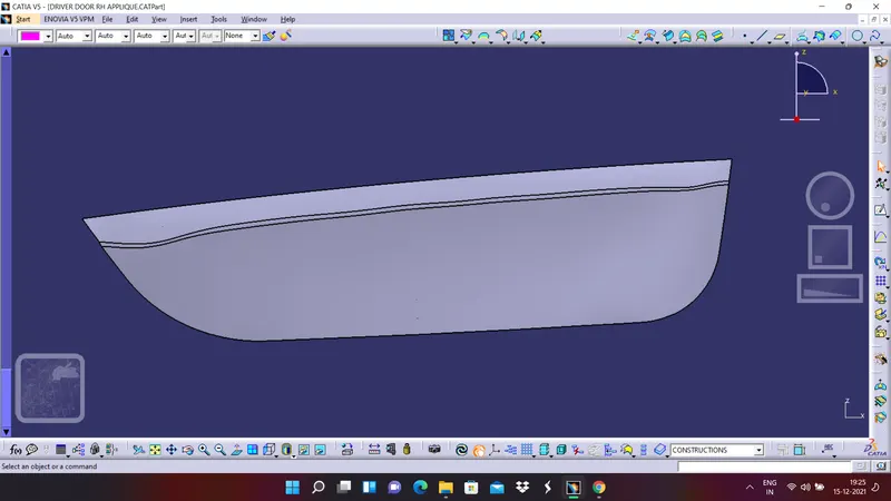
TOP VIEW
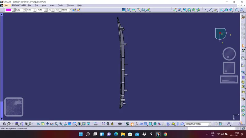
DRAFT ANALYSIS ON SOLID BODY
In a manner similar to the draft analysis performed on the class A surface create a draft analysis on the solid door applique body and observe the colour codes
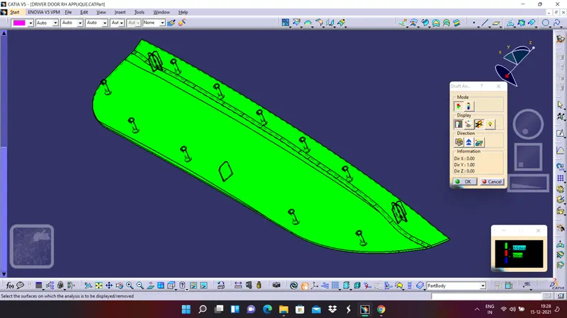
For a draft angle of 0.5 degrees our part is satisfying the draft analysis and hence our design in safe we can proceed for further operations.
DESIGN OF CLEARANCES ON COUNTER PART
1. Copy the sketch what we have for the four way locator and make it into construction element and draw a circle covering the four walls of the locator
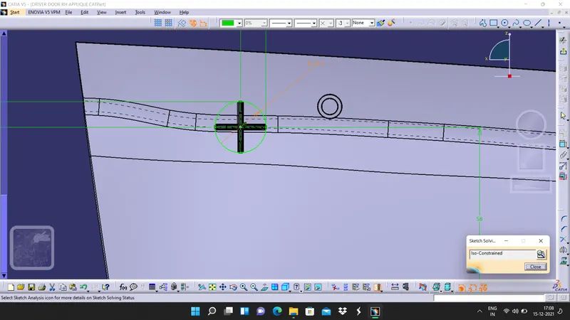
2. Inser a body and pad it to the required distance and give a proper draft to it.
3.Now remove this body with the counter part body
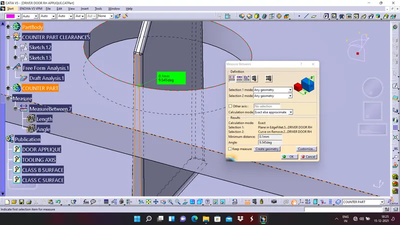
4. Measure the clearance between the four way locator and the removed portion and the clearance must be 0.1 milli meters. If incase if it is not 0.1 mm clearance and alter the radius of the circle and make sure the clearance is 0.1 millimeter.
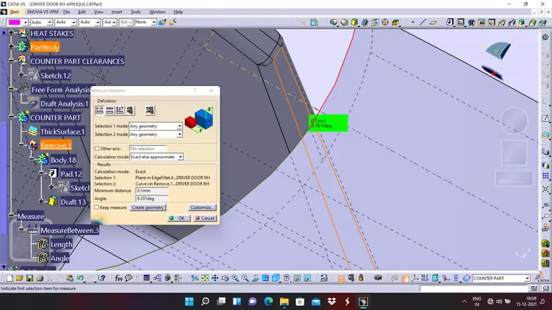
5. Now with the same parameters what we have used to translate the four way locator use the same cordinates and move the clearance part to the second four way locator and remove it wit the counter part body.
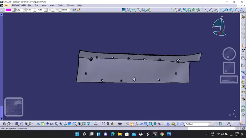
6. similar to the same repeat the same things for two way locator and heat stacks and the clearance value for two way locator is 0.1 millimeter and clearance for heat stacks is 0.5 milli meters respectively.
CONCLUSSION
The solid body of a door applique has been created from the given class A surface and all the features such as locators and heat stacks have been attached. Clearance has been provided to the counter parts. Draft analysis has been carried out and all the class A surface and final solid bodies satisfired the draft analysis condition and a report has been prepared by attaching all the images successfully.