Week 9 - Project 1 - Door Applique Design with Engineering Features
Aim:
Create door appliqué from given class A surface. Then create attachment feature like locators & heat stake considering the design rules.
Perform draft analysis on class A surface as well as final component.
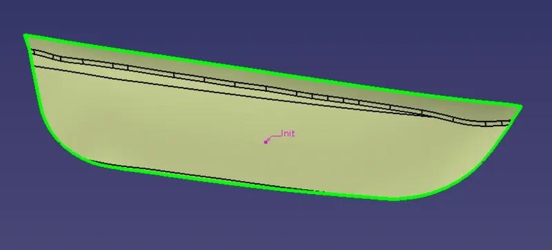
• Door applique surface:
there is no open surface found i door applique surface
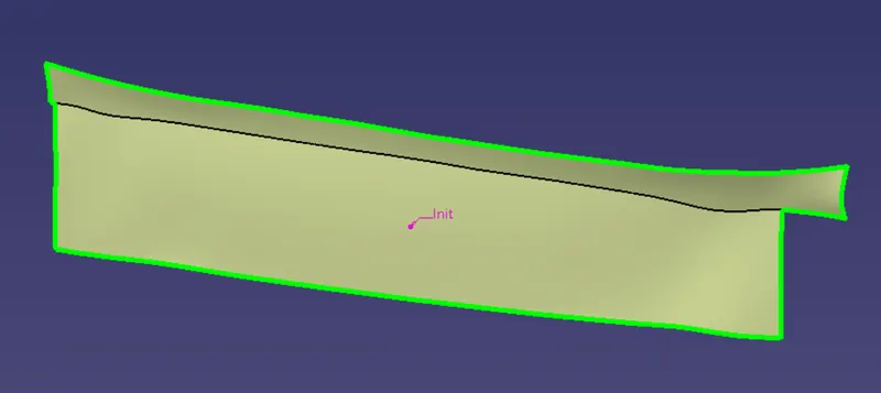
- Door attachment surface
there is no open surface found in applique surface
Heat stakes:
In manufacturing products with thermoplastic components, it is often necessary to join a thermoplastic to a part of dissimilar material,
whether it to be metal, a dissimilar plastic or other material.
Thermal staking is an assembly method that uses the controlled melting & reforming of a plastic stud or boss to capture or lock another
plastic or metal component of an assembly in place. The plastic stud protrudes through a hole in the component to be locked in place. The
heated thermal tip contacts the top of the studs, which melts & fills the volume of the tip cavity to produce a head, locking the component
in place.
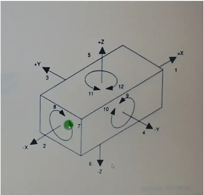
The degree of freedom defines as the capability of a body to move. Consider a rectangular box, in space the box is capabl
twelve different directions (six rotational and six axial). Each direction of movement is counted as one degree of freedom.
space has twelve degree of freedom.
Above figure shows a body in space and its possible direction of movement. The body can move two directions along the
mutually perpendicular axes; also can rotate about this axis either clockwise or anticlockwise. There are twelve degree of f
in space.
In machining process, in order to attain specific results, the degree of freedom is constrained by using work holding device
and locating devices.Method followed:
1. Checking continuity of class A surface.
2. Deciding feasible tooling direction & creating tooling axis.
3. Performing draft analysis on class A surface.
4. Creating class B surface from given class A surface.
5. Creating class C surface to join A & B class surface.
6. Creating solid feature by using closed surface.
7. Creating 4 way & 2 way locators.
8. Creating heat stakes.
9. Creating clearance holes for locators & heat stakes on attachment part
10. Performing draft analysis on final component.
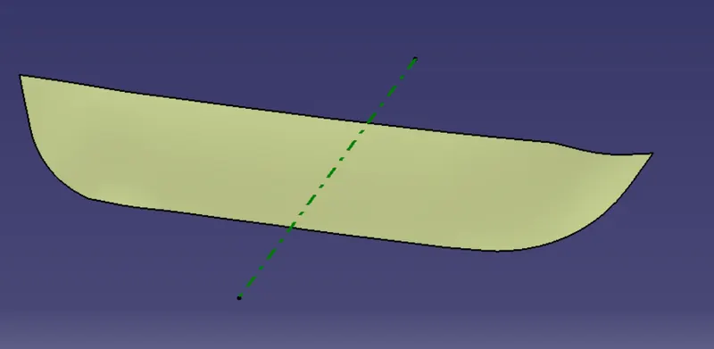
- CLASS A SURFACE ON DOOR APPLIQUE DESIGN
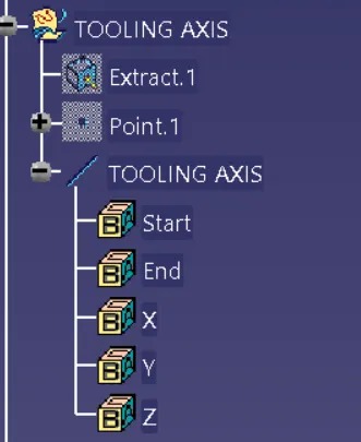
TOOLING AXIS
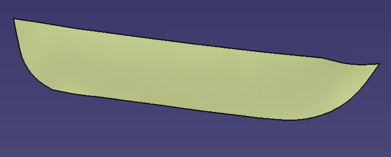
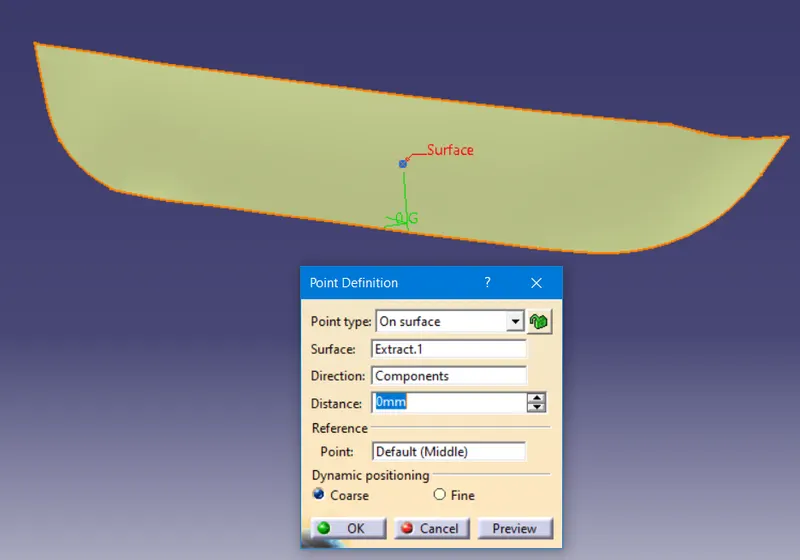
EXTRACT THE SURFACE AND CREATE THE POINT ON THE SURFACE USING THE OPTION ON SURFACE
EXTRACT THE POINT ON THE SURFACE ON THE DIRECTION OF Y AXIS
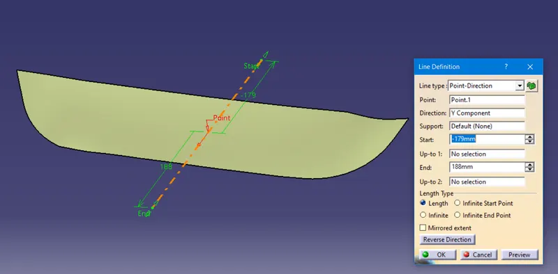
TOOLING AXIS HAS BEEN CREATED
DRAFT ANALYSIS
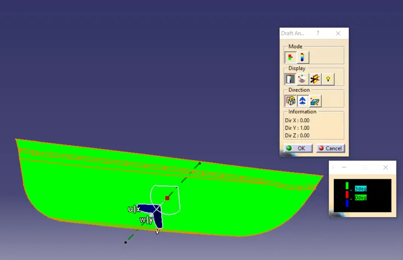
DRAFT ANALYSIS OF THE CLASS A SURFACE AS BEEN GIVEN ABOVE SO WE CAN SEE THAT ALL THE URFACE AS BEEN GIVEN MIN DRAFT ANGLE TO THE PART
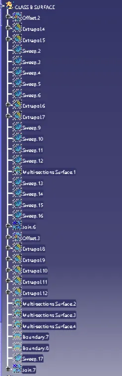
CLASS B SURFACE
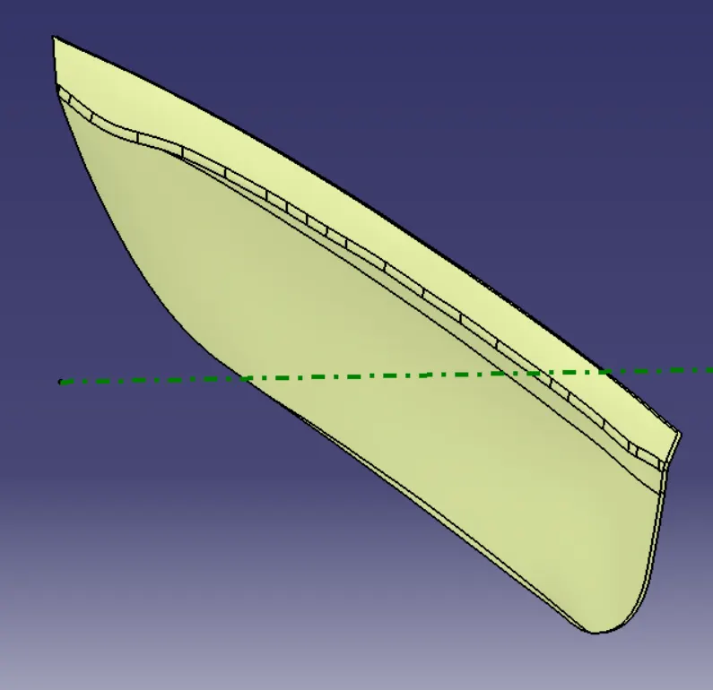
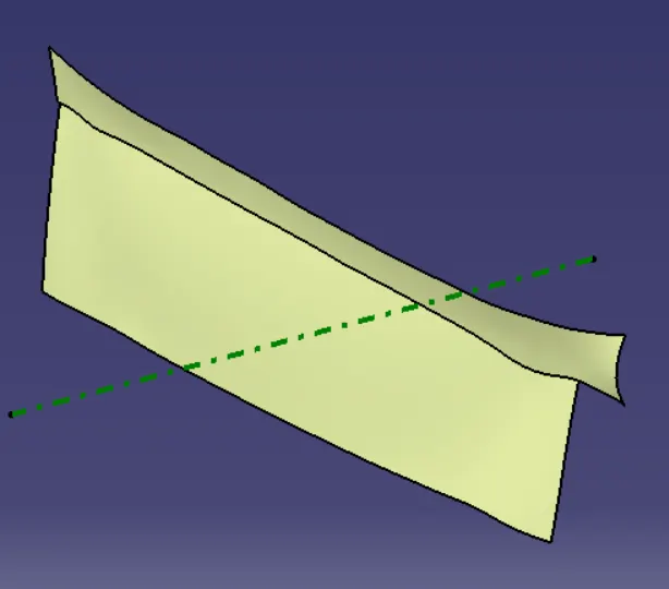
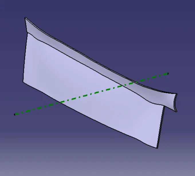
DIRECTLY OFFSET THE CLASS A SURFACE UPTO 2.5mm TO CREATE THE CLASS B SURFACE AND EXTRAPOLATE THE EACH EDGE OF THE OFFSET SURFACE
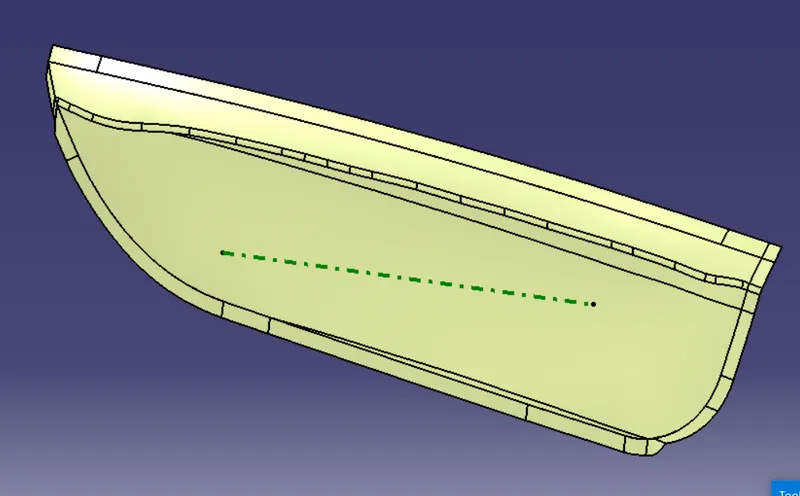
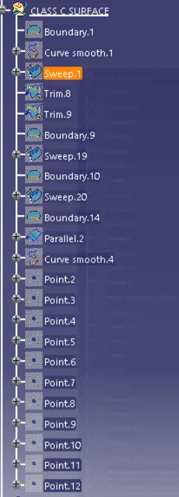
CLASS C SURFACE
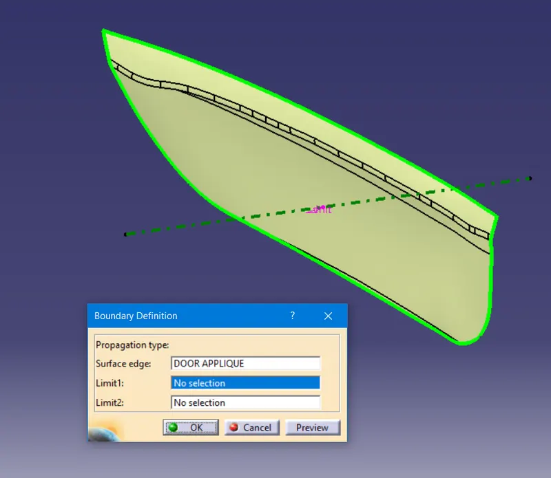
CREATE THE BOUNDARY FOR ENTIRE CLASS A SURFACE AND SWEEP.
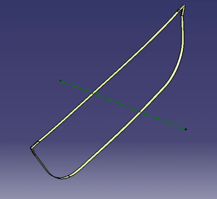
CLASS C SURFACE IS CREATED
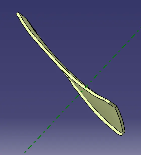
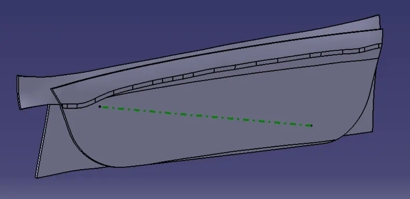
NOW TRIM THE CLASS A AND CLASS C SURFACE TO TRIM THE CLASS B SURFACE
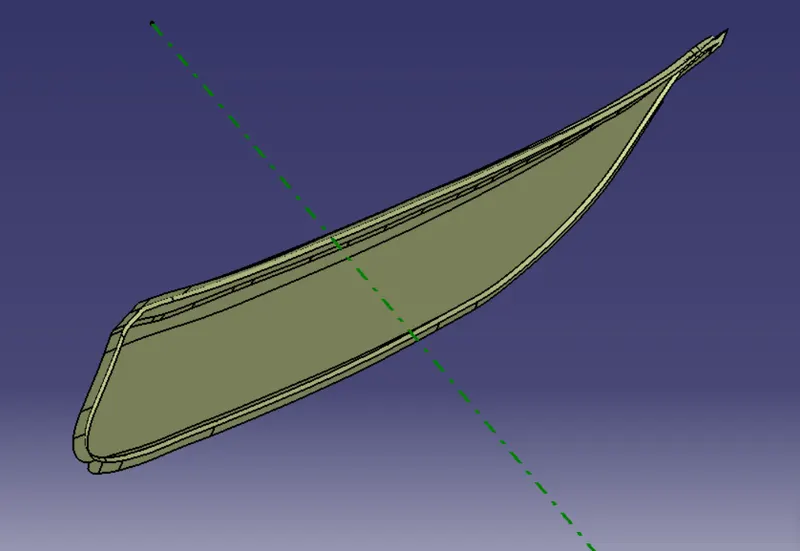
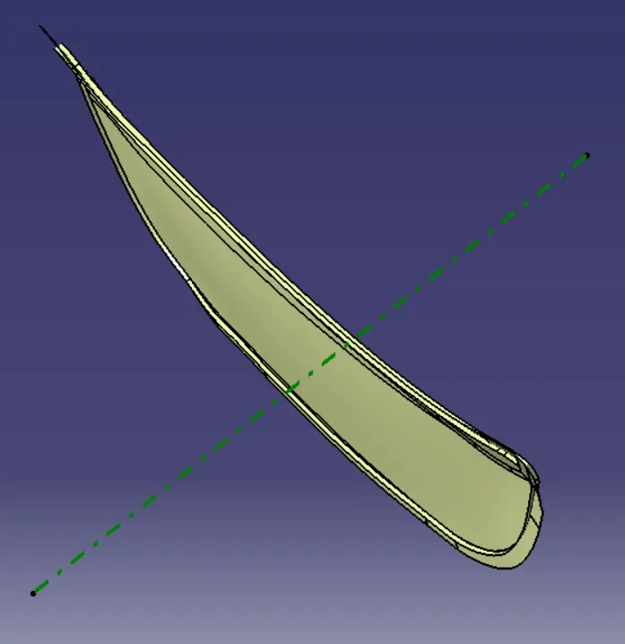
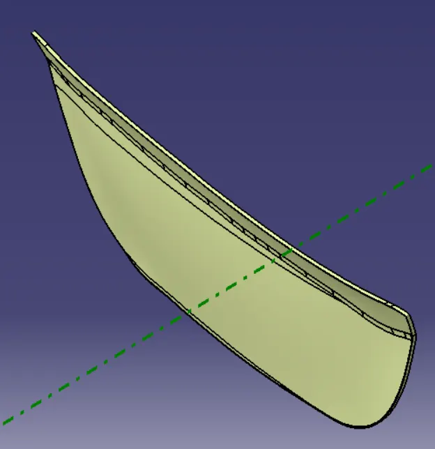
ENSURE THE ALL THE SURFACE IS CLOSED FOR THE PART CLOSED SURFACE
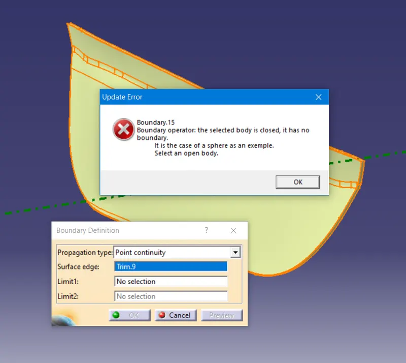
CONVERTING THE SURFACE DESIGN TO THE PART DESIGN
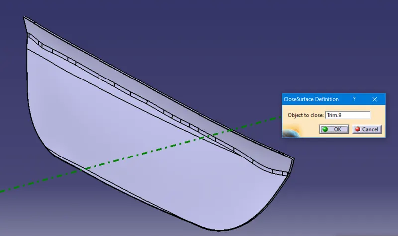
MAKE THE COUNTER PART THICKNESS UPTO 2.5mm
HEAT STAKES
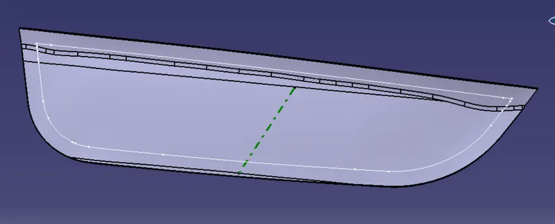
USE THE PARALLEL CURVE FOR MAKING THE HEAT STAKES
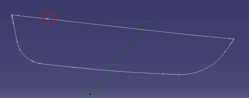
NOW PLACE THE PONIT ON THE CURVE AND USE THE POINT AND PLACE REPETATION
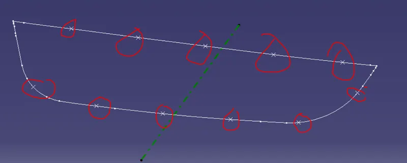
CREATING PLANE ON THE POINT THAT HAS BEEN CREATED FOR THR HEAT STAKES
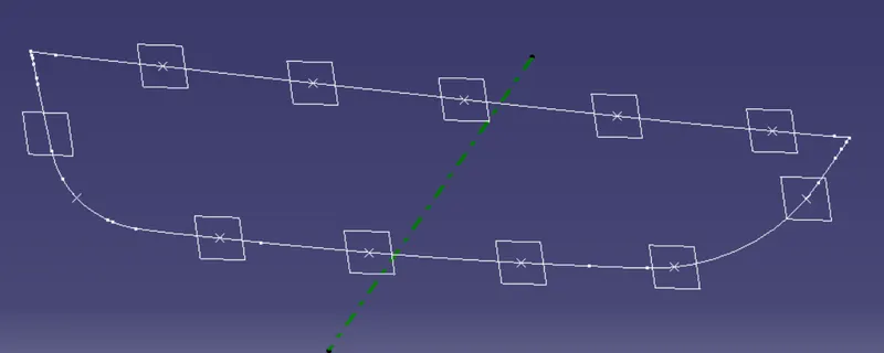
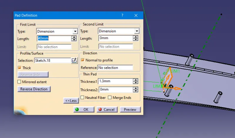
CRETATING THE SKETCH FORM THE DIFFERNT PLANES AND EXTURDE IT
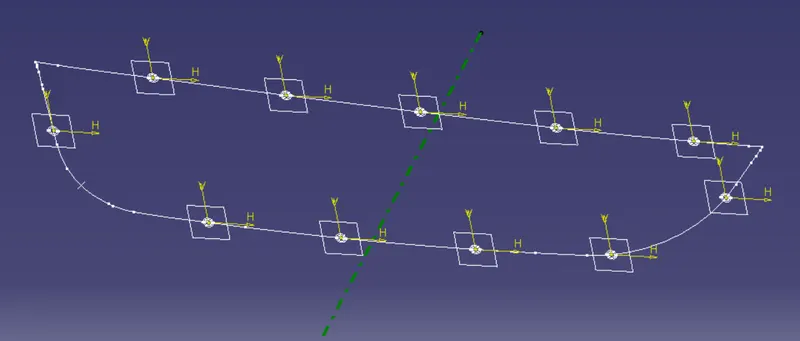
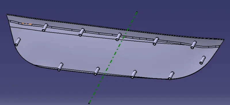
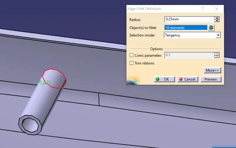
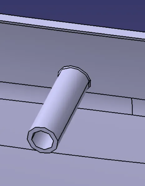
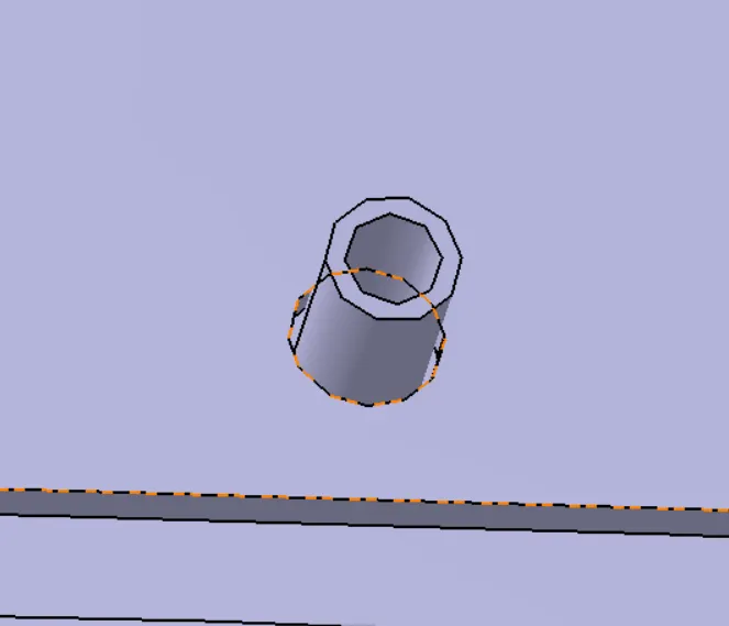
MAKE SOME FILLETS ON THE EDGES OF THE EXTURDE
FOUR WAY CONNECTOR
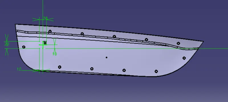
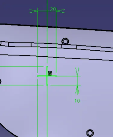
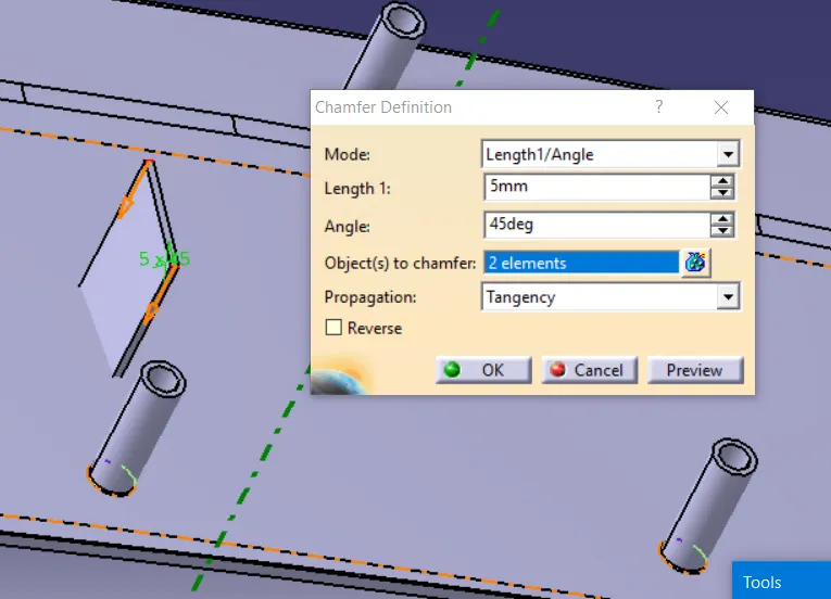
INCREASE THE HIEGHT AND THE THICKNESS OF THE CONNECTOR AND MAKE THE CHAMFER AND FILLET
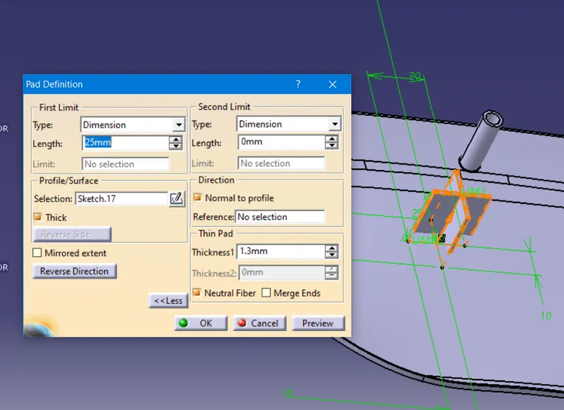
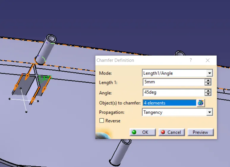
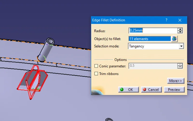
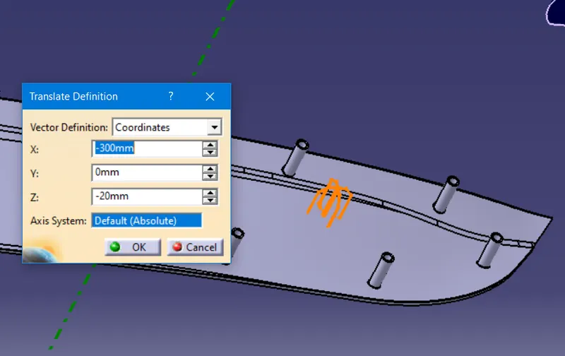
COPY AND PASTE THE FOUR WAY CONNECTOR IN SAME PART TO TANSLATE THE PART USING THE CO-ORDINATE AXIS OF THE PART
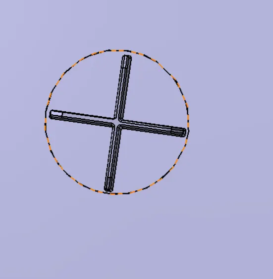
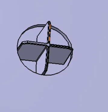
NOW MAKEING OF ONE WAY CONNECTOR IN SAME DOOR APPLIQUE
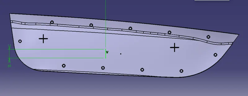
EXTURDE THE PART AND MAKE CHAMFER AND FILLET FOR THE ONE WAY CONNECTOR
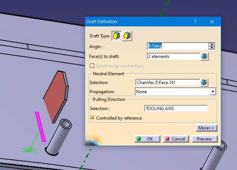
DRAFT THE CONNECTOR FOR MIN VALUE OF 0.5mm
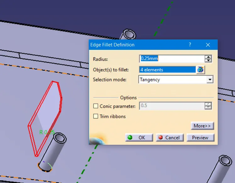
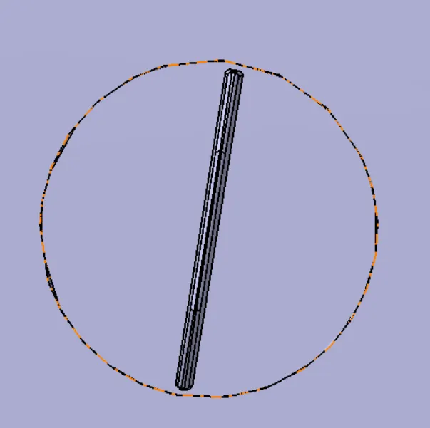
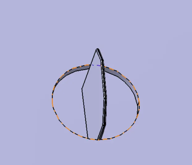
HEAT STAKES AND FOUR WAY CONNECTOR AND ONE WAY CONNECTOR HAS BEEN CREATED FOR THE DOOR APPLIQUE
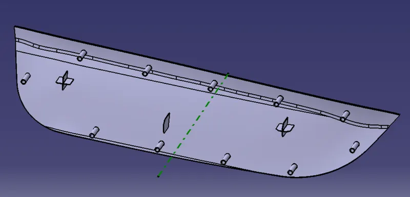
NOW WE GOING TO MAKE THE COUNTER PART CLEARNESS HOLES FOR THE HEAT STAKES AND CONECTOR PARTS
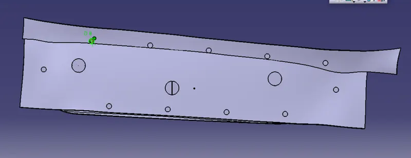
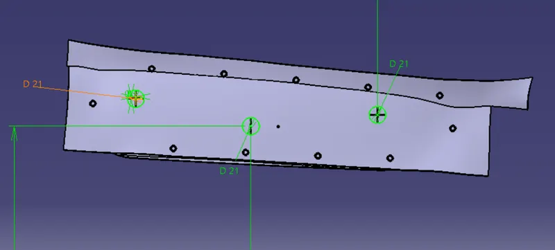
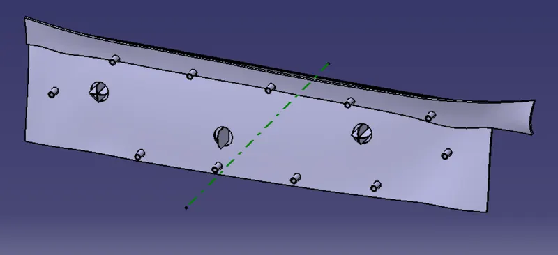
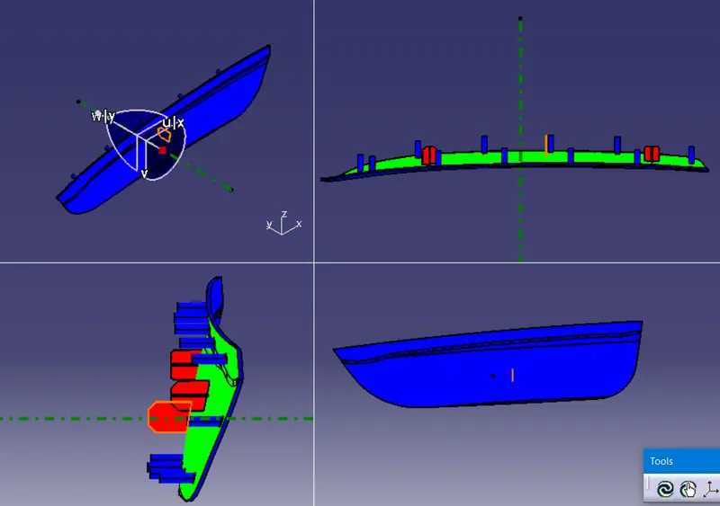
DRAFT ANALYIS FOR DOOR APPLIQUE
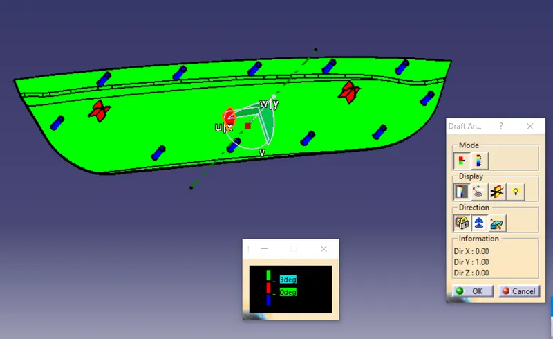
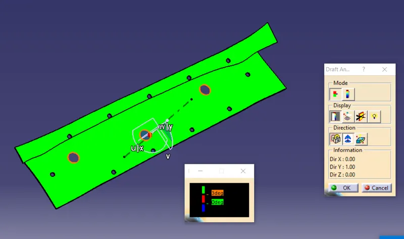
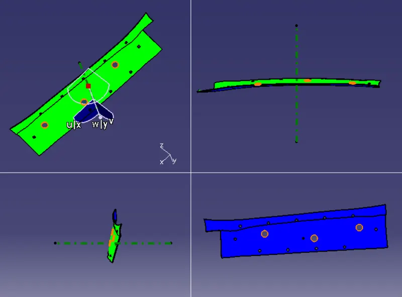
DRAFT ANSLYSIS FOR COUNTER PART
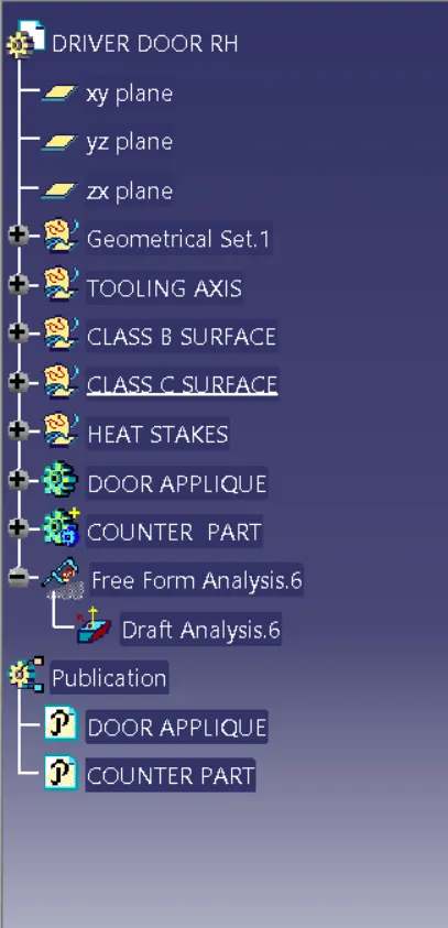
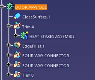
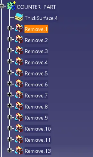
TREE STRUCTURE