Week 9 - Project 1 - Door Applique Design with Engineering Features
AIM
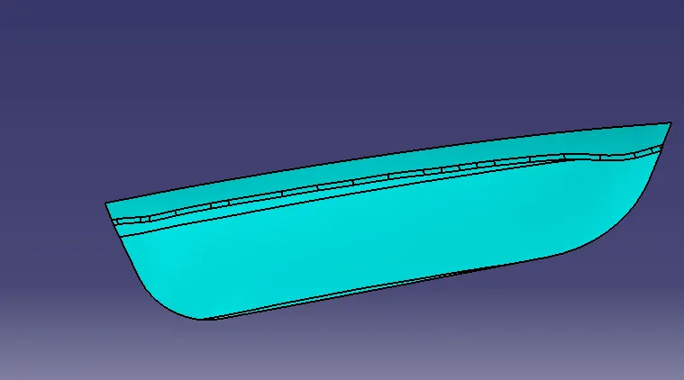
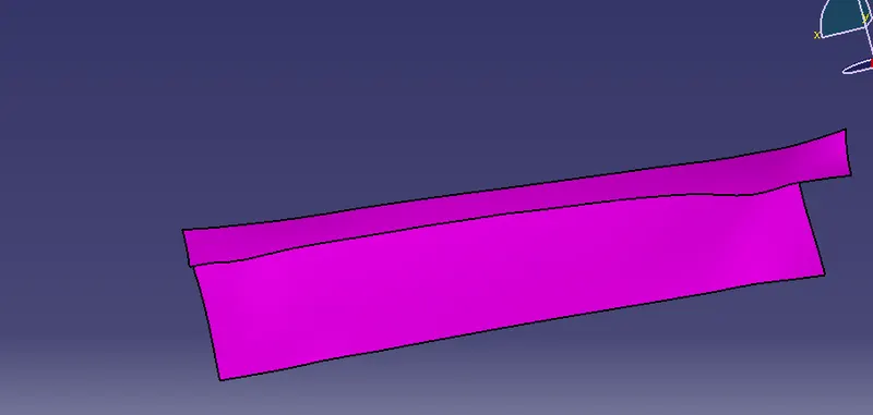
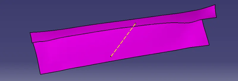
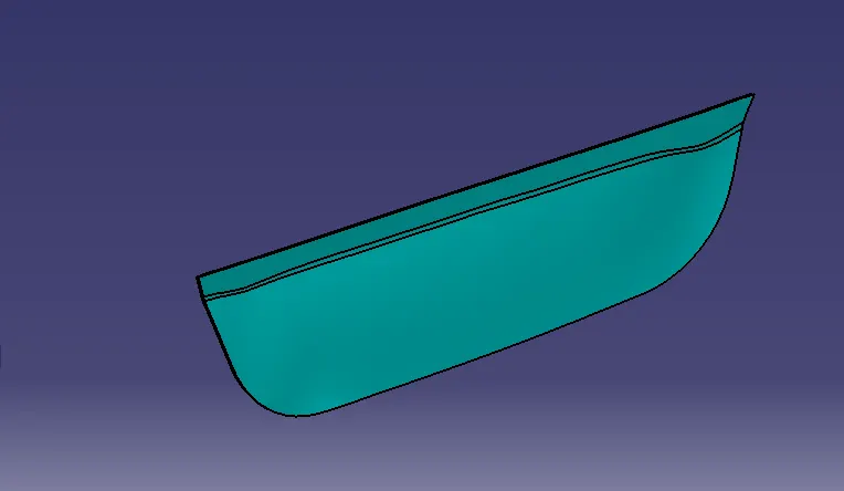
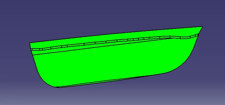
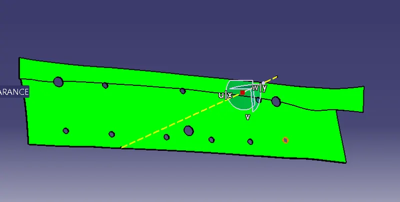
- Create the Base Bracket Plastic component through the given Class-A surface. To begin with, the tooling axis for the given Class-A Surface should be created meeting the requirements of the draft angle and at the end perform the Draft analysis on the model.
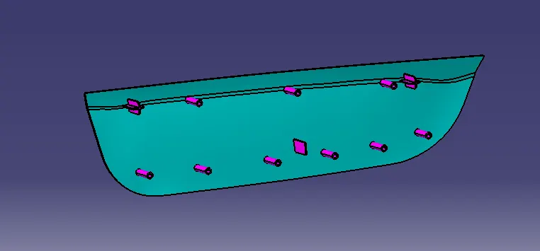
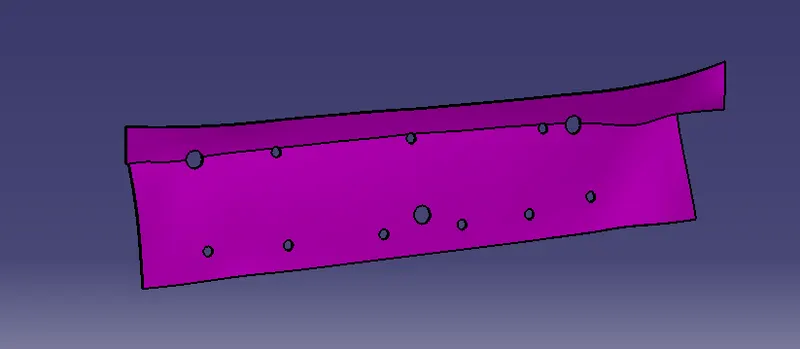
- Create the Heat Stakes and the locators considering the design rules mentioned in the video for the door applique.
OBJECTIVE
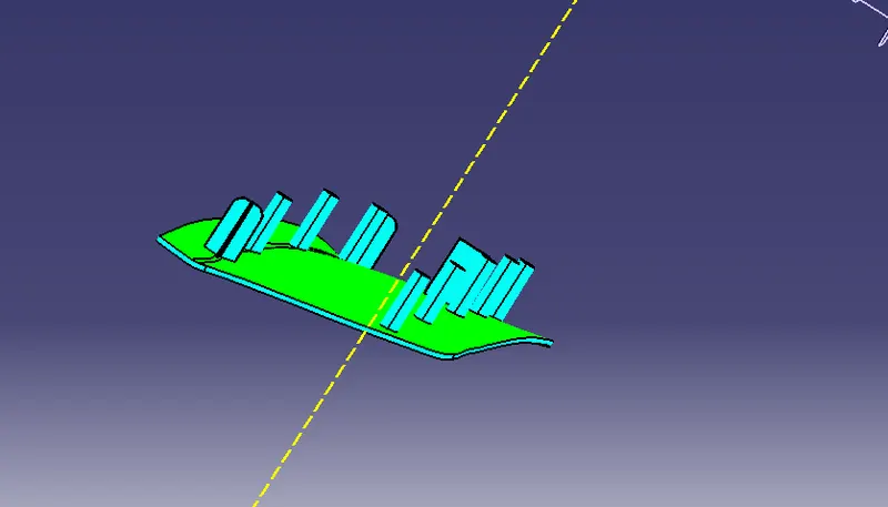
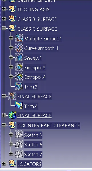
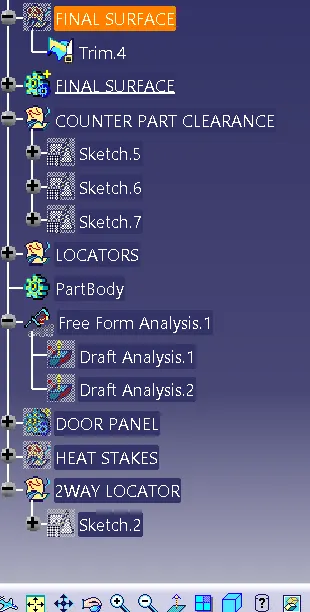
Design of an Automotive Plastic Component – Driver Side RH Door Applique Design with 4-Way, 2-Way Locators and Heat Stakes using industry principles and Design Rules. Concepts such as Rib design rules, Draft angles, Draft Analysis, Determining the Tooling Axis, Class A, Class B and Class C surfaces. The component is designed to manufacture maintaining a wall thickness of 2.5mm for Applique using Surface Design and Solid Design techniques in CAD package CATIA V5.
INTRODUCTION
Heat Staking:
- Heat staking also known as thermoplastic staking is the process of joining two dissimilar materials together.
- In heat staking we use local heating and cooling to raise the temperature of plastic components and allow plastic reforming to be carried out.
- This reforming can be used in a wide variety of applications.
- The Plastic Stud protrudes through a hole in the component to be locked in place.
- Heated thermal tips are used to melt the top of the studs which fills up the volume of the cavity to produce a head locking the component in place.
- The progressive melting of plastic under continuous pressure forms the head.
- When staking, the right combination of heat and pressure is critical.
- Applications range from staking plastic boss’s for assembly of car door panels to joining PCB’s to plastic housings.
- Benefits of this technique include; no vibration damage, no particulates, the ability to stake metalized coated applications and the capability to stake in difficult to access or restricted areas.
-
In short the Locators locate the component and lock 12 degrees of freedom whereas the Heat Stake is a Fixation which locks the Final DOF.
Advantages of Heat Stakes:
- Similar and dissimilar materials may be joined: metal to metal, plastic to plastic, metal to plastic.
- Accurate control operating within a small process window.
- Local heating resulting in no damage to surrounding materials.
- Processing of glass-filled materials.
- No mechanical vibration.
- Many heat-stake shapes possible through custom designed tools.
2 and 4 way locators:
- Locators are used to locate a job or a component to arrest its degrees of freedom using the 3-2-1 Principle which is arresting of 3 DOF's first, then 2 DOF's and last DOF in a sequence.
- A 4 way locator will look like a '+' and a 2 way locator will look like a '-' .
- Both these locators use the same Rib Design Rules and principles.
- These Locators are placed on the B side of the component and must have same height with respect to the B surface.
Guidelines For Rib Design:
|
Rib Specification |
No-Show Surfaces |
Show Surfaces |
|
Draft Angle |
Min 0.5º per side, Recommended 1.5º per side |
0.5º per side |
|
Rib Thickness at Base (w) |
0.5 * t |
0.4 * t |
|
Rib Thickness at top |
Min 0.75mm |
Min 0.75mm |
|
Rib Height (y) |
Max 5*t |
Max 5*t |
|
Spacing Between 2 Ribs (x) |
2*t |
2*t |
|
Fillet Radius (r) |
0.125*t |
Max 0.25mm |
|
Rib Root Dia |
± 30 % of t |
± 30 % of t |
|
y/x ratio for multiple ribs |
3:1 2:1 preferred |
3:1 2:1 preferred |
Fixture Design Rules:
-
For a fixture designer, the major portion of design time is spent deciding how to locate the workpiece in the fixture.
You know that any free body has a total of twelve degrees of freedom as below:
6 translational degrees of freedom**: +X, -X, +Y, -Y, +Z, -Z**
And 6 rotational degrees of freedom:
- Clockwise around X-axis (CROT-X)
- Anticlockwise around X-axis (ACROT-X)
- Clockwise around Y axis (CROT-Y)
- Anticlockwise around Y axis (ACROT-Y)
- Clockwise around Z-axis (CROT-Z)
- Anticlockwise around Z-axis (ACROT-Z)
You must fix all the 12 degrees of freedom except the three transitional degrees of freedom (-X, -Y, and -Z) in order to locate the workpiece in the fixture. So, 9 degrees of freedom of the workpiece need to be fixed By using the 3-2-1 method as shown below:
-
Rest the workpiece on three non-collinear points of the bottom surface (XY), and you will be able to fix the +Z, CROT-X, ACROT-X, CROT-Y and ACROT-Y degrees of freedom**.**
Now, rest the workpiece at two points of the side surface (XZ), and you will be able to fix the +Y and ACROT-Z degrees of freedom.
Now, rest the workpiece at one point of the adjacent surface (YZ), and you will be able to fix the +X and CROT-Z degrees of freedom.
So, you can successfully fixate 9 required degrees of freedom by using the 3-2-1 principle of fixture design.
- The jig and fixture are tools used for holding the workpiece in a correct location for mass production. Various types of fixtures are used in the industry. The 3-2-1 method is the fundamental principle for all types of fixture design.
s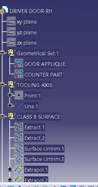
CONCLUSION
The Design of Automotive Plastic Component –Driver Side RH Door Applique Design with 4-Way, 2-Way Locators and Heat Stakes has been completed by using industry principles such as Rib design Rules, Draft Angles, Draft Analysis for Class A and Final enclosed surface, Tooling Axis creation and implementation, Class B and Class C creation and conversion to a solid part