Advanced Sheet Metal Design Using NX Cad Challenge_1_Casing Design
Objective:
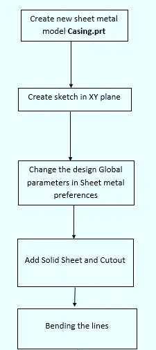
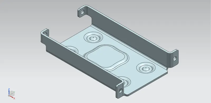
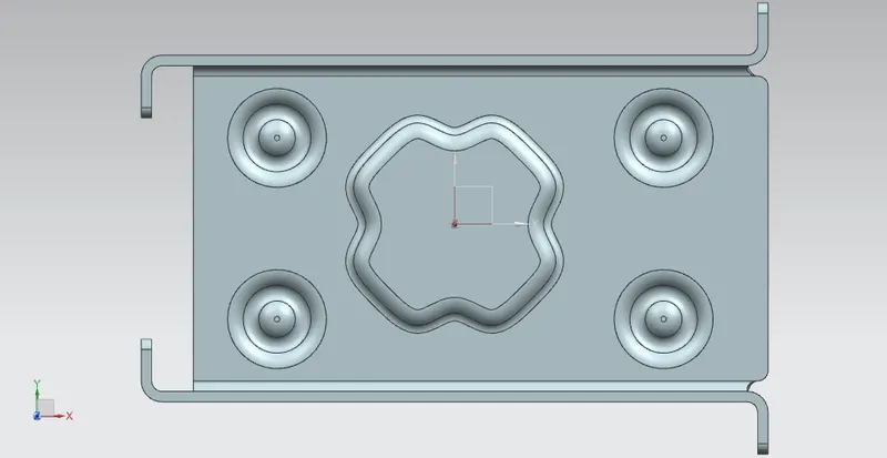
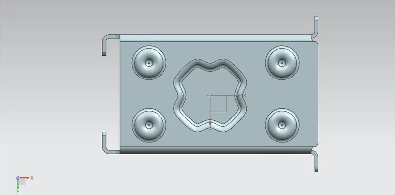
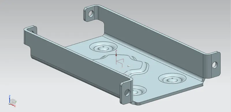
To creat sheet metal Casing design with dimples and beads by using NX CAD
Introduction:
Sketching and modeling of sheet metal casing design along with draft of the respective sheet metal design. These type of designs are used in aerospace, automotive et to increase strength and to form good structure
Design Methodology:
Tools and Features:
1. Tab: This feature used to creat sheet metal and provide existing thickness of the sketch
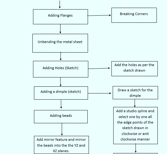
2. Flange: This feature is used to add flat flange at an angle to planar face and add bend between then two. It consists of bend region and web region
3. Breaking corners: The command is used to round or chamfer sharp corners of the tab and flang
4. Unbend: This feature is used to unbend the sheetmetal on stationary face
5. Bending: This command used for the bending of the created sheet metal using proper fillet and bending radius
6. Normal cutout: This command is used to cut a material by projecting a sketch on to the and then cutting perpendicular to the face intersected by the projection
7. Holes: This feature is used to creat holes as per the sketch drawn for the model
8. Punch/Dimple: This command used to lift area of the model inside a sketch that simulates a stamping stool
9. Beads: This feature is used to lift material along the contour of a sketch that simulates a stamping tool
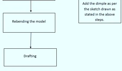
10. Rebending: This command helps to rebend the unbend command of the sheet metal after it is used when needed
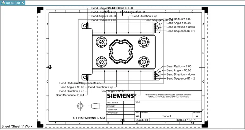
11. Flatpattern and Drafting : This feature is used to create a flat representation of a formed sheet metal part, the flattened version of the part is associative to the formed version this command is used to create a 2D representation of a 3D sheet metal part
Conclusion:
- The parts of the chopper are sketched and modelled in the NX CAD
- Learned about the sheet metal design and modelling
- Learned about the various Tools/Features used to create this model
- Did the Drafting of the sheet metal model