Week 9 - Project 1 - Door Applique Design with Engineering Features
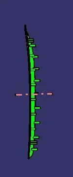
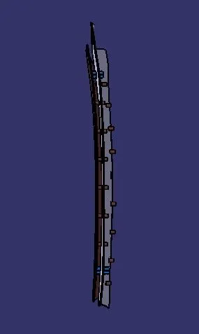
Aim: Create the Door Applique Plastic component through the given Class-A surface. To begin with, the tooling axis for the given Class-A Surface should be created meeting the requirements of the draft angle and at the end perform the Draft analysis on the model.
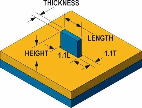
Create the Heat Stakes and the locators considering the design rules for the door applique.
THEORY:
HEAT STAKES:
The heat stake process is used in many high technology fields and consumer products manufacturing and offers many benefits.
- Processes & Procedures for Staking:
The direct contact method of staking applies force to heated metal probes, which contact posts then compress & form a stud head, For joining assemblies, metal to plastics, or joining two pieces of any other material. Excellent heat-staked results are possible when the post & material selection are initially configured for a heat staking application. Precise heat & pressure can reform posts from a wide variety of thermoplastic materials. Some of the most common examples are abs, polypropylene, polycarbonate, abs polycarbonate blends, Polypropylene/polycarbonate blends & many other engineering materials (even with as much as 30% filler).
- Design Guidelines:
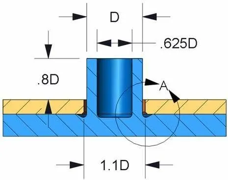
Very simple design guidelines are required for success. There are a number of factors that are essential in obtaining good heat stake results: post diameter, height, & geometry. Working height, (above the mating surface) should be approximately one & a half – two times the dia. This will result in a heat stake stud head dia. of approximately 1.5 – 3.0 times the post diameter. The selected material and the moldable thickness of the walls will determine typical diameters. For example, diameters can range from 0.04 – 0.09 inches.
- Post Types – Flat Profile, Dome, Cross-Shaped, Rosette:
Heat Staking posts & stud head geometry can vary as the application dictates. For through-hole fastening post: maintaining a flat-tipped probe tool for making a stud head into a flat profile is the easiest. Dome-shaped stud heads are aesthetically attractive plus provide a tight heat-staked assembly (typically, tighter than the flat-tipped profile configuration), but require a dome-shaped relief to be machined into the tip of the probe.
Cross-shaped post or hollow boss staking can be used where high retention assembly is required, but the design is limited because of the existing part constraints. The hollow & cross-post designs allow the creation of large posts or thick rib sections of uniform thick wall thickness while minimizing or eliminating sink marks on the A-side rib surfaces.
Rosette-shaped heat stake probes will flair out a hollow boss leaving the hole available for other operations (i.e. attaching additional components using self-tapping type hardware). A rosette-shaped flair stud head is aesthetically pleasing, plus has high pull strength characteristics (compared with other configurations previously mentioned), but requires more precision in the engineering and manufacturing of the probe.
- Conclusion:
Plastic Heat Staking is found in most industries and high technology fields that manufacture thermoplastic assemblies. Examples include consumer electronics, automotive, telecommunications, medical device manufacturers, computer manufactures, PCMCIA cards, Memory Modules, Flash Cards, electronic badges, etc.
Using the direct contact press, the heat stake method for assemblies is repeatable, economical, and safe. The number of posts heats staked at one time is only limited by the configuration design of the parts being assembled.
Heat staking and sealing parts of all shapes and sizes provide an excellent means of plastic assembly. The benefits of being extremely quiet, plus the versatility of doing a wide range of high tech posts; from threaded inserts and other metal components to microminiature equipment assembly by providing cost-effective means of adding or changing tooling make the process an excellent return on investment. In addition: the minimal wear characteristics of the tooling, low maintenance costs, high reliability of the equipment, and the added benefits of being safe for the environment to provide for a long, trouble-free, and clean operation.
LOCATORS: To position the work piece w.r.t. to the tool, to ensure precision in machining. The device to establish and maintain the position of a part in a jig or fixture.
There must be a definite relationship between the cutting tool and the surface of the workpiece in order to perform an accurate cutting operation. To achieve high precision in machining, the workpiece must be located accurately; it is called locating the workpiece. Location of components is significant to the design of jig and fixture so that it influences the accuracy of the final product. The locating device is designed so that each successive workpiece loaded must occupy the same position in work holding devices.
The locating device for a work-holding device mainly depends on the property of the workpiece and the overall machining process. The locating apparatus and method of clamping depend upon each other.
- Locating: dimensional and positional relationship b/w workpiece and tool.
- Locating Principle:
Basic rules for Location:
- Use a fewer locators. Locators spaced as much as apart possible and make sure complete contact of locating device.
- Reduce the degree of freedom of locating devices to zero.
- Locator must be foolproof. The component can only be loaded into the fixture in the correct position.
- Locator should provide swarf trap and clearance where it is essential to clear machining burr.
- 3-2-1 Principle of Location:
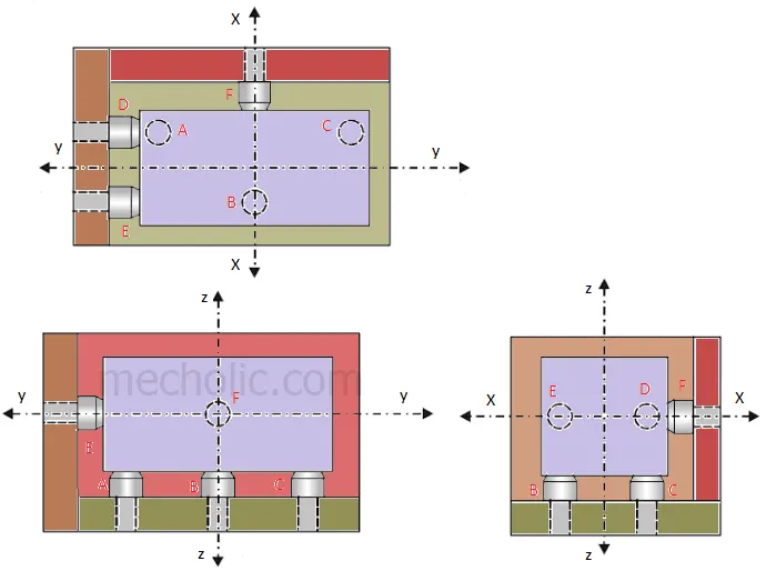
The 3-2-1 principle of location (six-point location principle) is used to constrain the movement of the workpiece along the three axes XX, YY, and ZZ. This is achieved by providing six locating points, 3 pins in the base plate, 2 pins in the vertical plane, and 1 pin in a plane that is perpendicular to the first two planes.
Degree of Freedom Controlled by 3-2-1 principle:
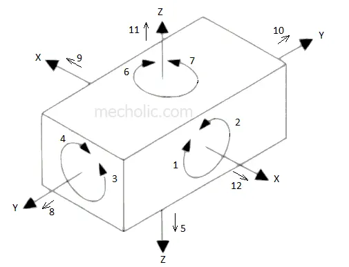
In this method, 9 degrees of freedom are controlled.
Pins A, B, C on the base plane ( a plane parallel to the plane which contains the X and Y axis) restrict the rotation of components about the X-axis and Y-axis. It also limits the downward movement of the component along the z-axis. Ie. 1,2,3,4 and 5 degrees of freedom are restricted.
Pins D, E is in the plane parallel to the plane containing X and Z axes. It prevents the rotation of components about the Z-axis (6, 7 degrees of freedom) and the movement of the body along the Y-axis towards one direction (8 degrees of freedom).
The last pin F is in a plane parallel to the plane contains Y and Z axes. It restricts the movement component along X-axis in one direction.
The three remaining degrees of freedom 10, 11, 12 are unrestricted. It facilitates the loading of the component in the fixture. These three degrees of freedom may restrict after loading components by using clamping devices.
TOOLING AXIS:
The tooling axis is an axis in which direction we can easily pull out the product from the core and cavity. It is the main axis through which a mold moves from the cavity.
DRAFT ANALYSIS:
Designers of plastic parts and mold tooling manufacturers can use the Draft Analysis tool to check the correct application of the draft to the faces of their parts. With draft analysis, you can verify draft angles, examine angle changes within a face, as well as locate parting lines, injection, and ejection surfaces in parts.
Criteria: To perform a draft analysis, specify the following criteria:
- The direction of Pull: Select a planar face, linear edge, or axis to define the draw direction. You can adjust the direction of pull by selecting the Adjustment triad and dragging the triad.
- Face classification: When selected, the analysis examines each face on the model, based on the draft angle. When you click Calculate, each face is displayed in a different color. With this option cleared, the analysis generates a contour map of the face angles. You must specify both the Direction of Pull and the Draft Angle with either type of analysis.
- Reverse Direction: Click to change the draw direction.
- Draft Angle: Enter a reference draft angle, and then compare that reference angle to those currently existing on the model.
DOOR APPLIQUE PLASTIC COMPONENT:
Tooling axis for the given Class-A Surface:
The tooling axis is an axis in which direction we can easily pull out the product from the core and cavity. It is the main axis through which a mold moves from the cavity.
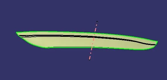
Using the tooling axis created along the x and y-axis, these tooling axes are used for the creation of the tooling axis by a bisecting method where the two lines and points will be selected as inputs.
To create the tooling axis, we used initially intersect feature to create the outer boundary. Draw two lines on the faces boundary for the creation of the tooling axis. Now draw a bisecting line with the help of both inclined lines. This bisecting line is called the tooling axis.
Screenshots of the Draft analysis report for the given Class-A surface of the Door Applique:
A draft is required to eject the mold from the cavity. The draft is necessary for ejection of the molded part easily. If the draft will not apply then some problems could be created in the production of models. So Draft analysis is done in designing part of the Door Applique after completing the tooling axis creation.
Use the compass to define the new current draft direction. After that lock the draft direction.
Quick analysis mode:
In this image, the green color shows that the minimum draft angle is 3 degrees angle and more than that.
Here on the right-side color box shows blue color shows a 0 to 3 degrees angle and the red color shows a negative angle as measured with the tooling axis.
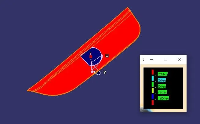
Full analysis mode:
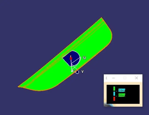
In this image red color shows that the minimum draft angle is 20 degrees angle and more than that and the light blue color shows that the draft angle is between 2 to 20 degrees angle.
Here on the right-side color box shows green color at 0 degrees angle and yellow color shows a -2 degrees angle and the blue color shows -20 degrees draft angle as measured with the tooling axis.
Screenshots of the Draft analysis report for the plastic final component of the Door Applique:
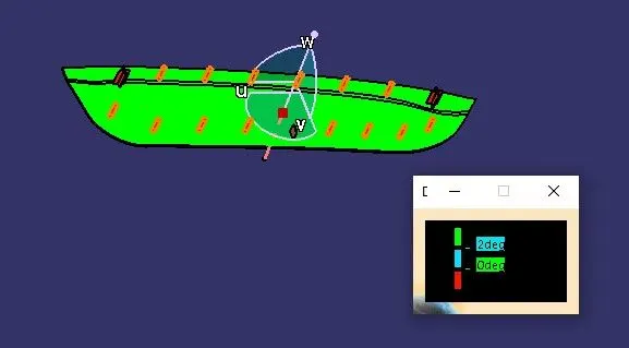
Quick analysis mode:
In this image, the green color shows that the minimum draft angle is 2 degrees angle and more than that.
Here on the right-side color box shows blue color at 0 to 2 degrees angle and the red color shows a negative angle as measured with the tooling axis.
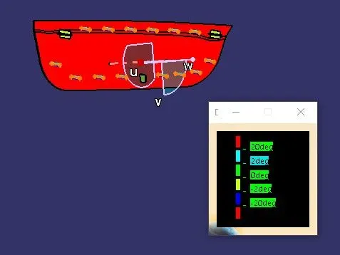
Full analysis mode:
In this image red color shows that the minimum draft angle is 20 degrees angle and more than that and the light blue color shows that the draft angle is between 2 to 20 degrees angle.
Here on the right-side color box shows green color at 0 degrees angle and yellow color shows at -2 degrees angle and blue color shows -20 degrees draft angle.
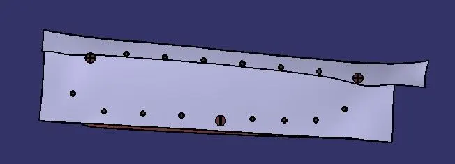
Conclusion: In the Door Applique design, we designed two 4- way locators and one 2- way locator. These locators restrict the translation motion of the Door applique in both the x-axis direction and the Y-axis directions but in the z-axis directions, it will move for ejection and the rotational motion of the Door applique is restricted in all the directions i.e it will not rotate in the XY, YZand ZX plane.
So, Degrees of freedom is restricted in XX-axis is 2 and in the XY plane is 2.
The degrees of freedom is restricted in YY-axis is 2 and in the YZ plane is 2.
The degrees of freedom is restricted in the ZZ-axis are zero and in the ZX plane are 2.
The total Degrees of freedom are restricted is 10.
Degrees of freedom is 2 for Door Applique.
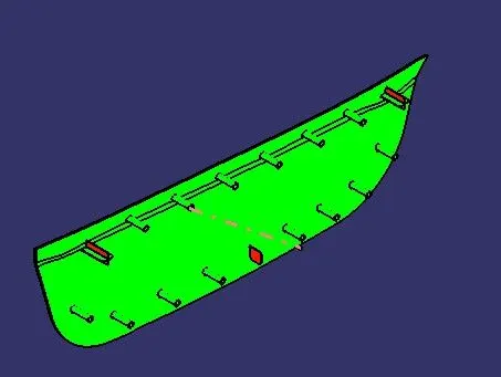
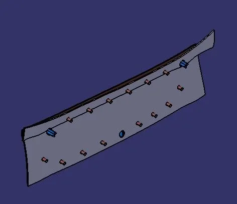
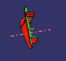
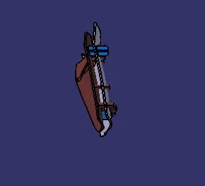
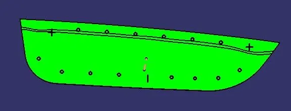
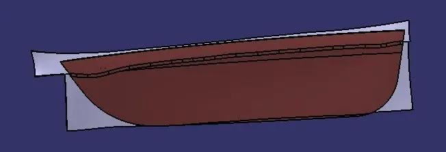
Screenshots of the completed design in various orientations:
Isometric view:
Front view:
Side view:
Top view: