Radar Mast & Final Assembly of Yacht
Radar mast:
Commands and features used: Line, spline, circle, rectangle, straight slot, fillet, trim, extrude, sweep, revolve, mirror, offset, geometric plane, projected curve.
Design with the fully defined sketch:
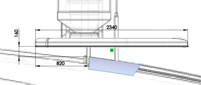
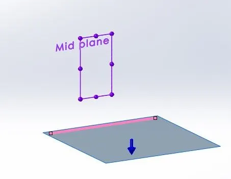
Select the midplane and draw a horizontal line of 2340mm in length. The start point of the line is 160mm vertically and 820mm horizontally away from the origin.
Create a new plane with the reference to the midplane and the line.
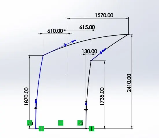
Select the new plane and draw the four splines according to the blueprint. Added the dimensions for the fully defined sketch.
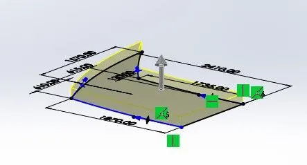
Extrude the sketch of 140mm depth upward.
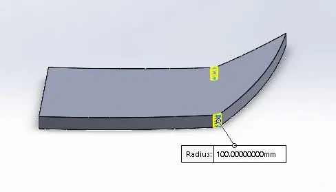
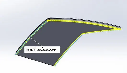
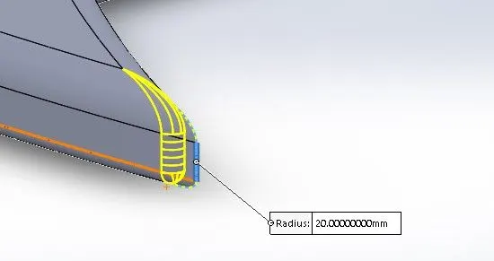
Gave fillets of 100mm and 20mm to the required edges.
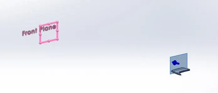
Create a new plane with the reference to the front plane at a distance of 20950mm.
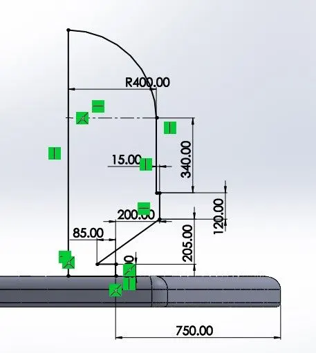
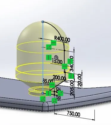
Select the new plane and draw the sketch according to the blueprint. Added the dimensions for the fully defined sketch.
Use revolve feature on the sketch about the long vertical line.
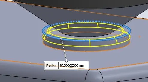
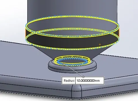
Gave fillets of 10mm and 30mm to the required edges.
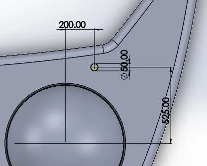
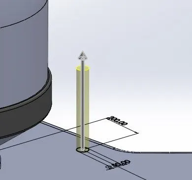
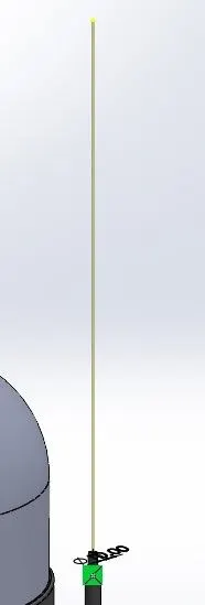
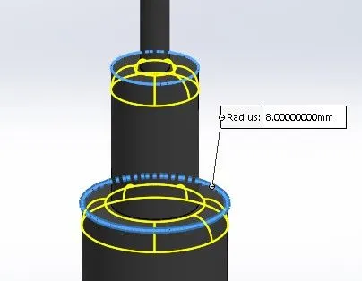
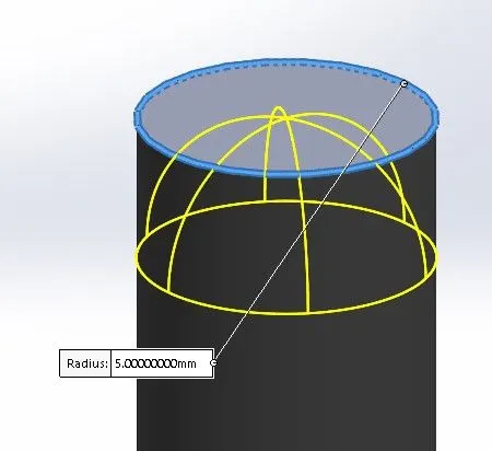
Select the surface and draw a circle of 50mm diameter that is 200mm horizontally and 525mm vertically away from the center of the revolved part.
Extrude the circle of 345mm distance.
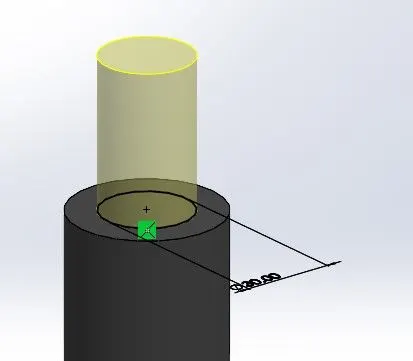
Select the upper surface of an extruded circle and draw a circle of 30mm diameter.
Extrude the circle of 50mm distance.
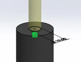
Select the upper surface of an extruded circle and draw a circle of 10mm diameter.
Extrude the circle of 1800mm distance.
Gave fillets of 8mm and 5mm to the required edges.
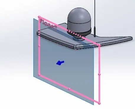
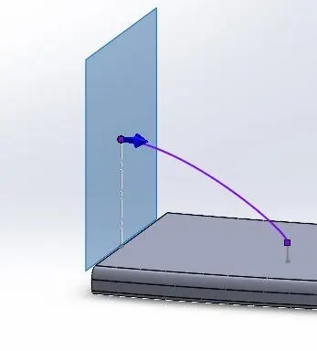
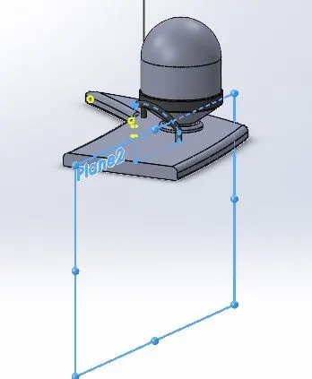
Create a new plane with the reference to plane2 at a distance of 250mm.
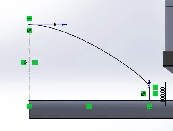
Select the new plane and draw a vertical line of 100mm. Draw a spline from the endpoint of the vertical line and coincident with the midplane.
Create a new plane with the reference to spline and point.
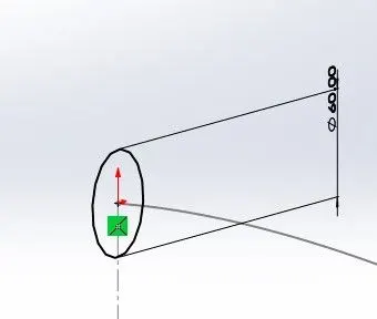
Select the new plane and draw a circle of 60mm that is pierced with the spline.
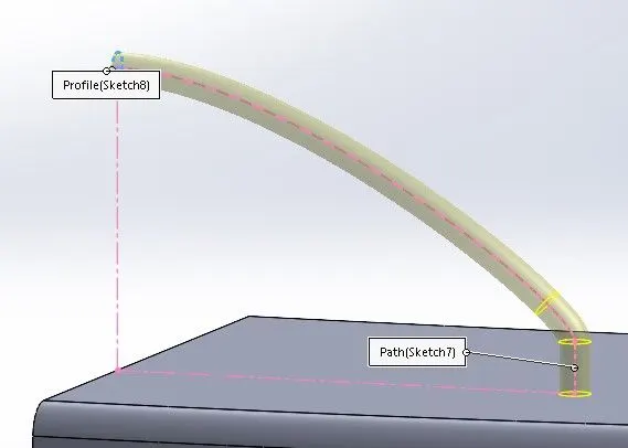
Use the sweep feature on the circle and the spline.
Mirror the swept part about the plane2.
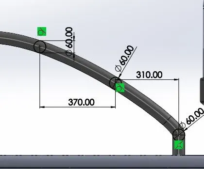
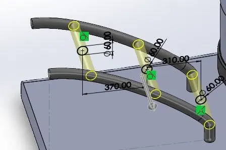
Select plane2 and draw three circles of 60mm diameter on the spline sketch. One circle at the joining of spline and the vertical line. The second circle is 310mm away from the 1st circle. The third circle is 370mm away from the 2nd circle.
Extrude the circles up to the next.
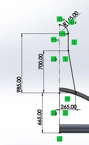
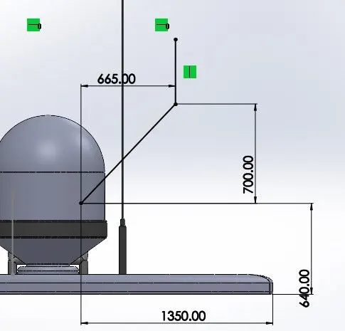
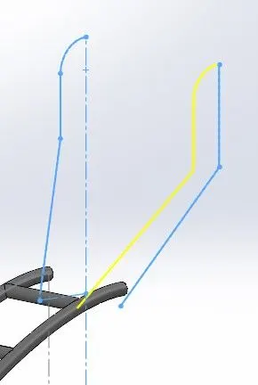
Select plane2 and draw a construction line of 265mm that is 665mm away from the edges. From that draw, an inclined line of 700mm and draw a vertical line that is at 985mm distance from the construction line. From the vertical line draw a 3-point arc of 145mm radius.
Select the midplane and draw an inclined line, the lower point is 1350mm horizontally and 640mm vertically away from the edge and upper point is 700mm horizontally and 665mm vertically away from the edge. Draw a vertical line.
Create a new projected curve with the help of both sketches.
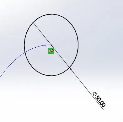
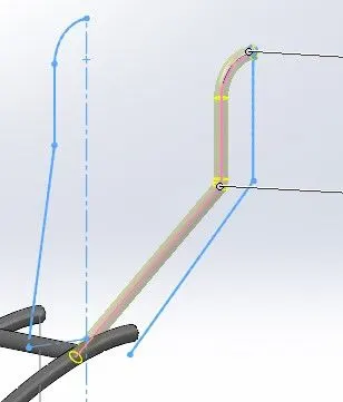
Select the midplane and draw a circle of 50mm that is pierced with the projected curve.
Use the sweep feature on the circle and the projected curve.
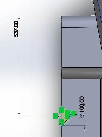
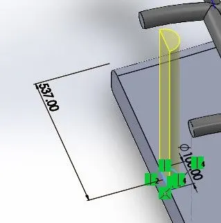
Select the surface and draw a semicircle of 100mm diameter that is 537mm away from the edge.
Extrude the semicircle of 740mm distance.
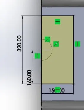
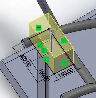
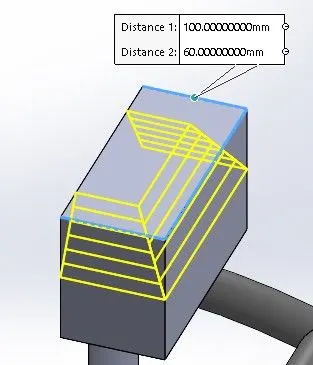
Select the surface and draw a rectangle of 320mm breadth and 150mm length.
Extrude the rectangle of 200mm distance.
Gave chamfer of 100mm and 60mm distance to the edges.
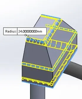
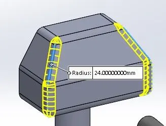
Gave fillets of 24mm radius to the required edges.
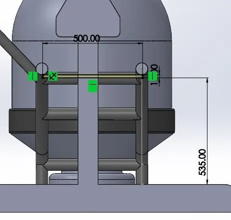
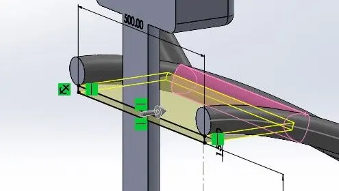
Select the midplane and draw a rectangle of 500mm length and 15mm breadth that is 535mm away from the edge.
Extrude the rectangle up to the pink surface.
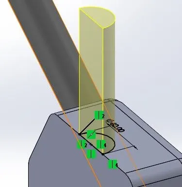
Select the surface and a semicircle of 60mm diameter.
Extrude the semicircle of 180mm distance.
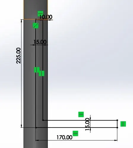
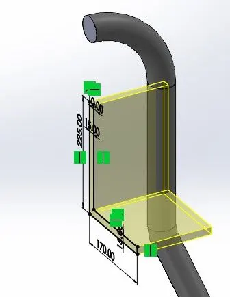
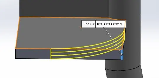
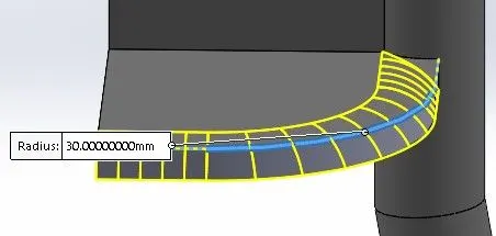
Select the midplane and draw a rectangle of 225mm breadth and 15mm length that is 10mm away from the edge. Draw another rectangle of 15mm breadth and 170mm length.
Extrude the sketch of 150mm distance.
Gave fillets of 100mm and 30mm radius to the required edges.
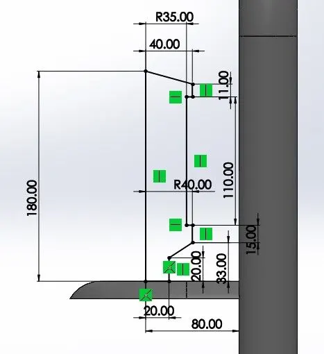
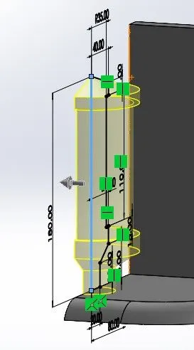
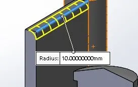
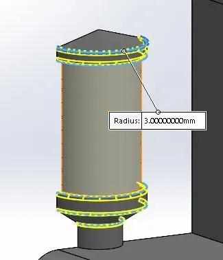
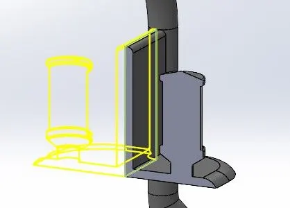
Select the midplane and draw a sketch according to the blueprint and added the dimensions to it.
Use revolve feature on it about the 180mm line with 180 degrees angle.
Gave fillets of 10mm and 3mm radius to the required edges.
Mirror the part about the surface.
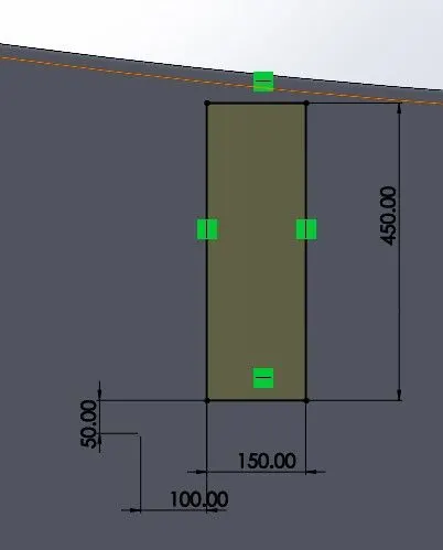
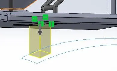
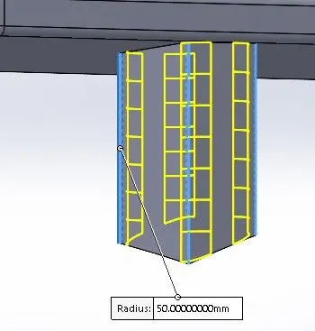
Select the lower surface and draw a rectangle of 450mm breadth and 150mm length.
Extrude the sketch up to the next.
Gave fillets of 50mm radius to the required edges.
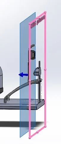
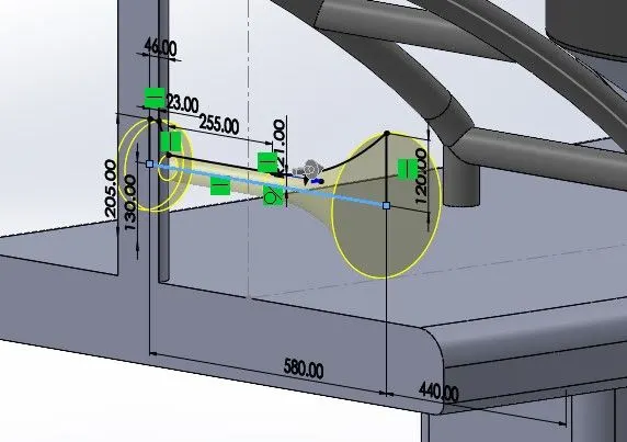
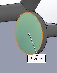
Create a new plane with the reference to the midplane at a distance of 270mm.
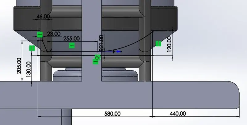
Select the new plane and draw a sketch for the horn and added the dimensions to it.
Revolve the sketch about the 580mm line.
Gave dome of 20mm to the surface.
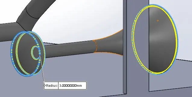
Gave fillets of 3mm radius to the required edges.
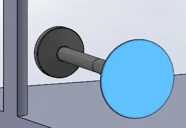
Use shell feature of 2mm thickness on the blue surface.
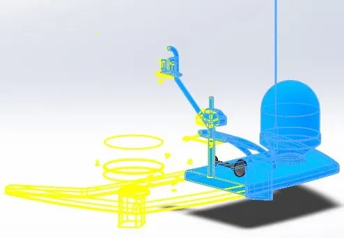
Mirror the body with merged option about the surface.
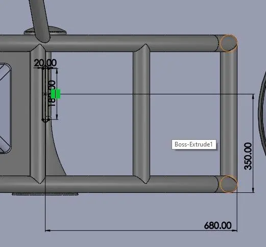
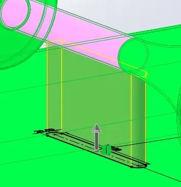
Select the surface and draw a straight slot of 20mm breadth and 180mm length that is 350mm vertically and 680mm horizontally from the edge.
Extrude the sketch up to the pink surface.
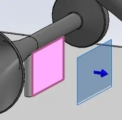
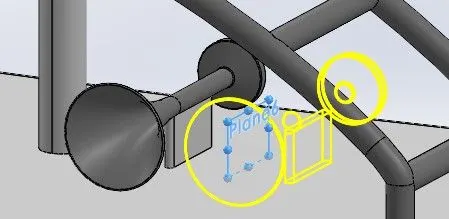
Create a new plane with the reference to a pink surface at 130mm distance.
Mirror the horn part about the new plane.
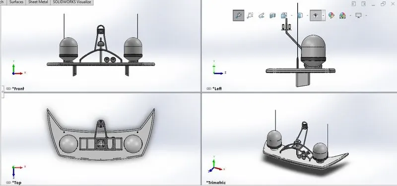
Views:
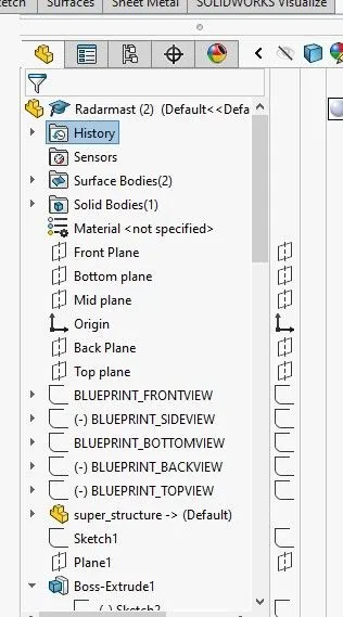
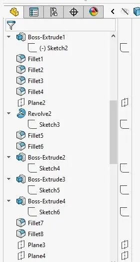
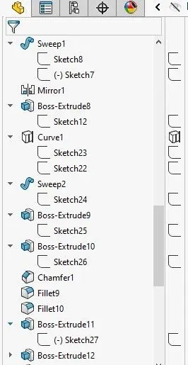
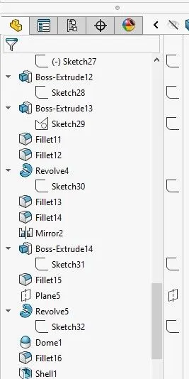
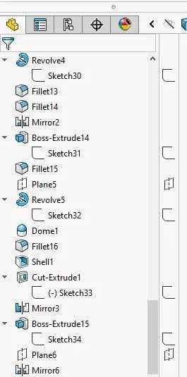
Features Tree:
Assembly and Modeling of the Yacht:
Objective:
- The objective of this project is to create part models of the Yacht and assembly the parts using Solidworks.
- To add Decal, Camera view, and Environment Scene of the assembly.
- To create the photo-realistic Model of this Yacht assembly and rendering the assembly using Solidworks Phtotview 360.
Introduction:
This project explains the designing of different parts of the Yacht and assembling them to get a complete model of the Yacht using Solidworks. It also tells about the rendering of the model using Solidworks 360 to make the Yacht more natural and realistic.
Modeling and Assembly Features:
The various modeling features used for modeling the Yacht are discussed as follows:
- EXTRUDE BOSS/BASE:
Extrude Boss/Base is one of the important and very useful tools in Solidworks CAD software to create solid 3D models. It extrudes a sketch or selected sketch contours in one or two directions to create a solid feature. That means, if you have a closed contour sketch drawing, then you can add materials to that contour and convert it into a 3D model.
- EXTRUDE CUT:
Extrude cut is another cool feature that helps to remove materials from the 3D model. It is just the opposite of to extrude boss/base feature because it cuts a sketch profile while extruding. You can cut in both directions and are mainly used for creating holes, channels, slots, etc.
- REVOLVE BOSS/BASE:
Revolved Boss or Base is a SolidWorks feature tool that is used to create a solid 3D model around an axis. You can revolve the sketch around an axis to add materials to it. You can access revolved boss/base from both command manager and menubar.
- SWEEP:
SWEEP is the one feature in Solidworks that helps sweep a closed profile along a closed or open path. In this session, we are going to use a simple 3D object as an exercise to demonstrate the use of the SWEEP command in Solidworks.
- FILLET:
A fillet is a tool used to round an edge, vertex, or face on both inside and outside of a 2D or 3D model. The fillet type, location, and radius of the fillet are defined.
- CHAMFER:
SolidWorks chamfer tool is one of the useful tools, which helps to cut (45-degree angle with the normal surface) or make edges or corners (vertex) of 3D model in straight.
- MIRROR:
The mirror tool in Solidworks is used to copy a 2D or 3D object about a reference line or plane. Creates a copy of a feature, (or multiple features), mirrored about a face or a plane.
- SHELL:
In Solidworks, Shell feature having their own property manager which controls the application of the shelling process on designed models. Here, both uniform thickness and multi-thickness shelling can be easily done by using this feature tool.
- LINEAR & CIRCULAR PATTERN:
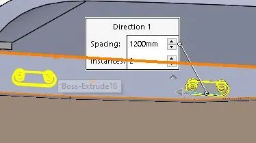
The Linear Pattern Command is used to drive features, faces, or bodies in a linear direction. The Circular Pattern Command is an excellent tool used to replicate features, faces, or bodies in a rotational manner about an axis.
- PROJECTED CURVES:
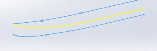
A projected curve is a 3D curve that represents the intersection of two extruded surfaces of two sketches on intersecting planes.
- SURFACE EXTRUDE:
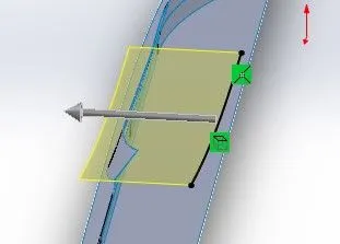
In SolidWorks, the Extruded Surface tool is provided to extrude a closed or an open sketch to create an extruded surface.
- SURFACE LOFT:
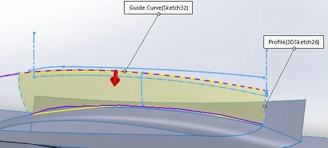
The loft feature is an important tool for (surface) modeling in SolidWorks. The loft feature creates a shape by making transitions between multiple profiles and guide curves. This tool is very valuable for modeling complex surfaces.
- SURFACE SWEEP:
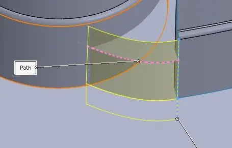
Sweep creates a surface by moving a profile (section) along a path. A sweep can be simple or complex. To generate the swept geometry, the software creates a series of intermediate sections made by replicating a profile at various positions along the path.
- SURFACE FILL:
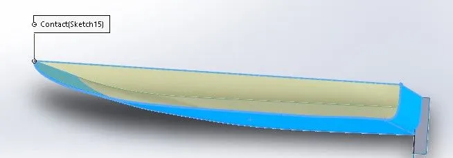
The surface fill joins the solid, removing the features inside. The model with Filled Surface applied and Merge result cleared. The surface fill creates a new surface, and the features inside remain. Forming a solid is possible if all the boundary entities are open surface edges.
- SURFACE TRIM:
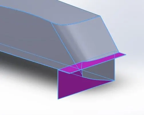
To trim a surface, Create two or more surfaces that intersect at one or more points, or create a surface that intersects with a plane or has a sketch on its face.
- Mates:
Mate operation is the basic tool for assembling the parts. Mates are used in SOLIDWORKS to constrain and connect different parts in an assembly. There are various mate operations such as coincident, parallel, perpendicular, tangent, concentric, lock, etc.
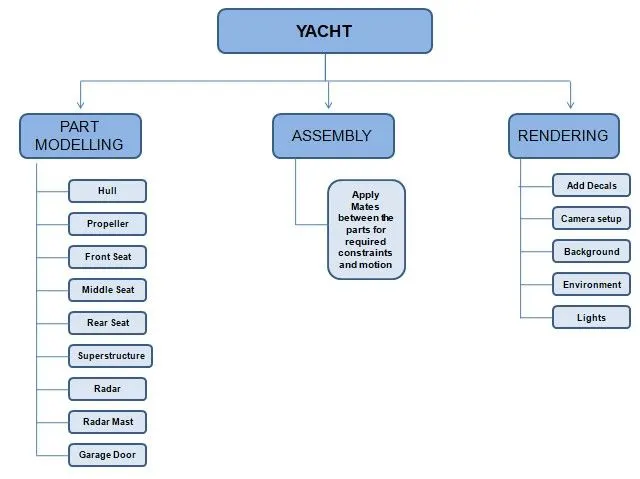
Designing Approach:
Modeling of the Yacht:
Propeller:
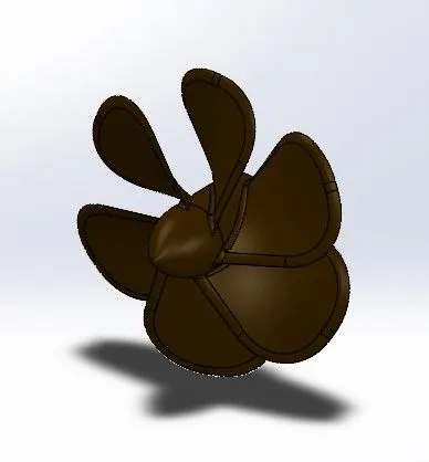
A propeller is a device with a rotating hub and radiating blades that are set at a pitch to form a helical spiral, that, when rotated, exerts linear thrust upon a working fluid, such as water or air. Propellers are used to pump fluid through a pipe or duct or to create thrust to propel a yacht boat through water or an aircraft through the air. The blades are specially shaped so that their rotational motion through the fluid causes a pressure difference between the two surfaces of the blade which exerts a force on the fluid.
Propeller is modeled by fully defined sketches, features used like revolve, loft, filets extrude cut, circular pattern. Add appearance to the propeller.
Hull:
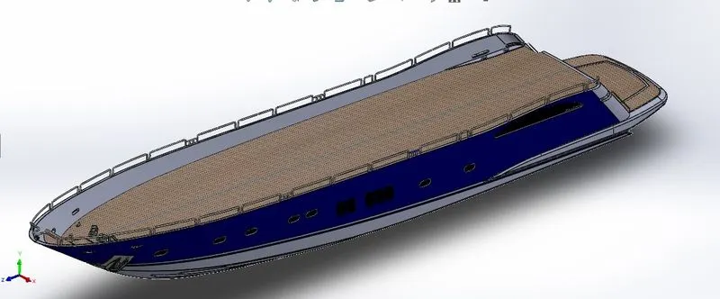
A hull is the watertight body of a ship, boat. The hull may open at the top, or it may be fully or partially covered with a deck. Atop the deck may be a deckhouse and other superstructures, such as a funnel, derrick, or mast. The line where the hull meets the water surface is called the waterline. There is a wide variety of hull types that are chosen for suitability for different usages, the hull shape being dependent upon the needs of the design.
There are three basic types of motor yacht hull: full-displacement, semi-displacement, and planing, which have progressively higher cruise speeds and hourly fuel consumption with increased engine power.
- Full-displacement hulls move the water up and out of the way of the vessel, making a wave. They are limited in speed by the square root of the waterline length multiplied by a factor, depending on the units used. Added horsepower cannot increase the maximum speed, only the size of the waves produced.
- Semi-displacement hulls allow speeds that are faster than the hull speed of a displacement vessel because they rise somewhat out of the water and create smaller waves. They also provide greater comfort than planning hulls.
- Planing hulls require sufficient power for the boat to slide up onto the surface, which avoids the need to use power to lift water out of the way of the vessel. Such vessels have flat surfaces on the undersides.
The Hull is modeled by fully defined sketches, features used like revolve, loft, filets, extrude, extrude cut, linear pattern, surface extrudes, surface loft, surface trim, extend surface, surface sweep, sweep boss/base, surface fill, etc. Add different appearances to the parts of the hull for looking good and realistic view.
Front Seat, Middle seat, and Rear seat:
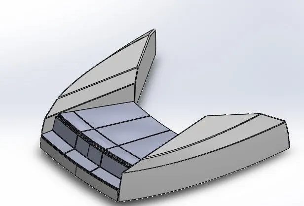
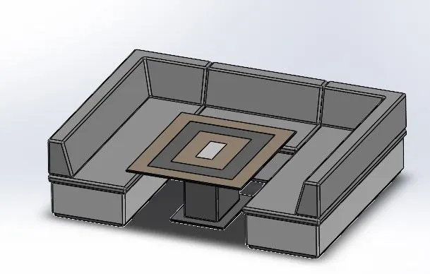
A yacht seat is designed primarily for comfort. It is usually an upholstered armchair with a slightly inclined back. The seats is modeled by fully defined sketches, features used like revolve, loft, filets, extrude, extrude cut, surface extrudes, surface loft, surface trim, extend surface, surface sweep, sweep boss/base, surface fill, etc. Add different appearances to the parts of the hull for looking good and realistic view.
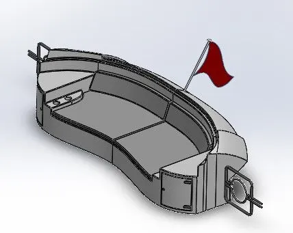
FRONT SEAT MIDDLE SEAT REAR SEAT
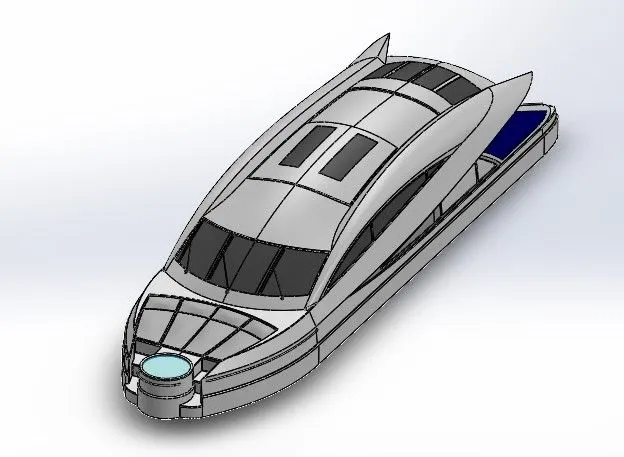
Super Structure:
A superstructure is an upward extension of an existing structure above a baseline.
On watercraft, the superstructure consists of the parts of the ship or a boat, that project above its main deck. This does not usually include its masts or any armament turrets.
The size of a watercraft's superstructure can have many implications in the performance of ships and boats since these structures can alter their structural rigidity, their displacements, and/or stability. These can be detrimental to any vessel's performance if they are taken into consideration incorrectly.
The height and the weight of the superstructure on board a ship or a boat also affect the amount of freeboard that such a vessel requires along its sides, down to her waterline. In broad terms, the more and heavier superstructure that a ship possesses (as a fraction of her length), the less the freeboard that is needed.
Radar and Radar Mast:
Radars on ships or boats are used to detect other ships or boats and land obstacles, to provide bearing and distance for collision avoidance and navigation at sea. They are electronic navigation instruments that use a rotating antenna to sweep a narrow beam of microwaves around the water surface surrounding the ship to the horizon, detecting targets by microwaves reflected from them, generating a picture of the ship's surroundings on a display screen.
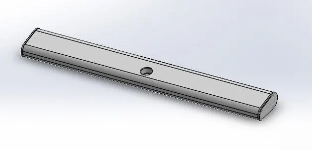
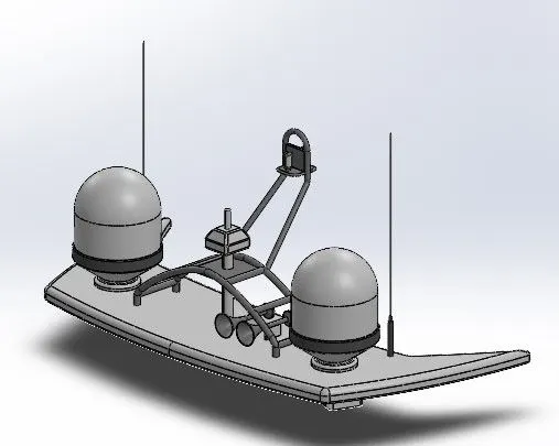
RADAR RADAR MAST
Garage Door:
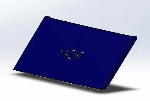
The garage door is mainly used to keep hidden the things in the garage. It is the closing of the garage on the boat or ship. It is designed according to the need of shape and design. The Garage Door is designed from the split part of the superstructure. First design half part and then mirror about the midplane.
ASSEMBLY OF THE CHOPPER:
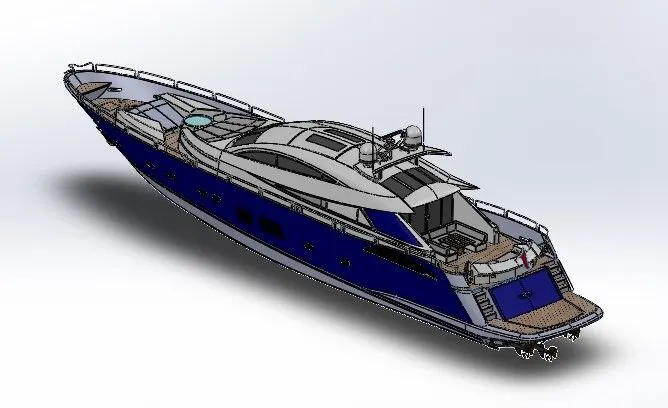
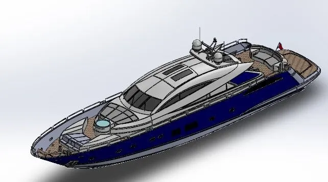
All the parts modeled were imported to assemble them. In assembly, the mating feature was often used to locate and relate the parts with one another. The hull was inserted initially and fixed. The other components were inserted and set with a reference to the hull.
- RENDERING OF THE YACHT:
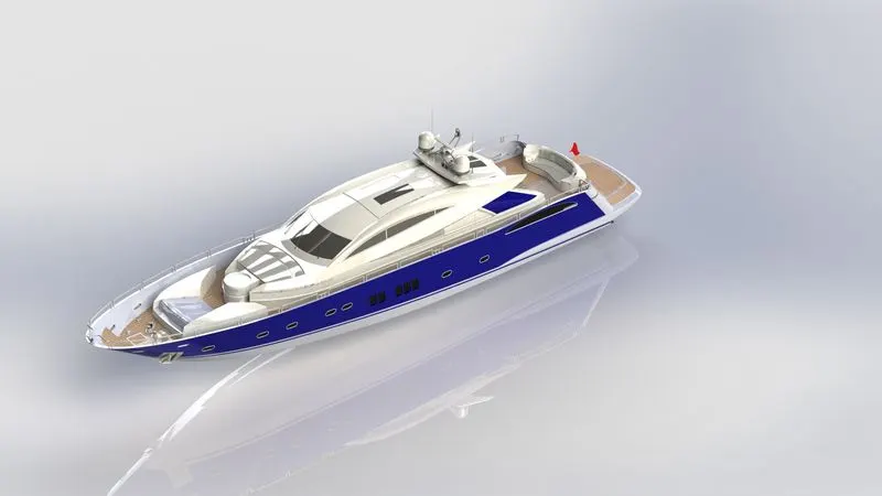
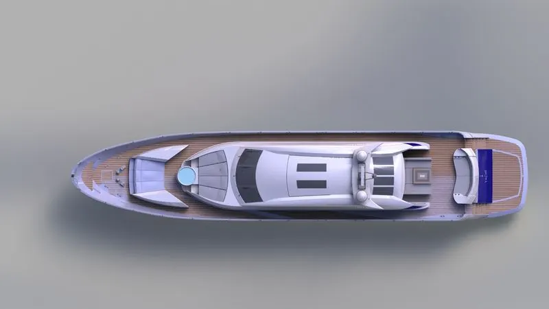
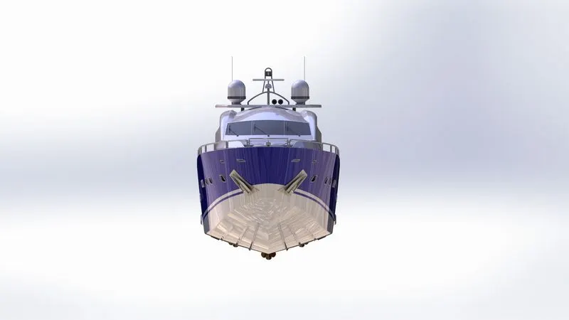
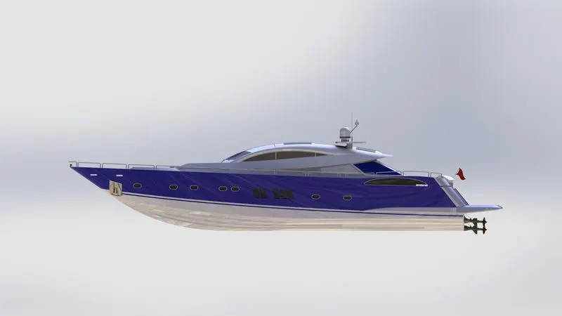
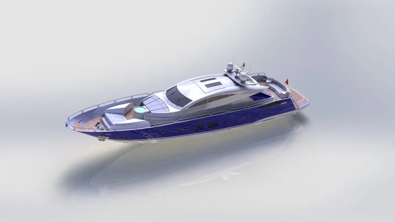
In rendering, the Sunseeker Predator Yacht was made to set up in such a way to look natural and unique. Decals were added to the body parts. Views and light directions were changed. Using Solidworks Photo-view 360, the appearances, background scenes, and camera views were changed. Then final rendering was done to make the chopper, a cool and realistic one.
Isometric View:
Top view:
Front view:
Right view:
Camera view:
- CONCLUSION:
- Design all the parts of the Yacht with the fully defined sketches.
- Assembly of the Yacht in Solidworks 2020.
- Rendering of the Yacht in Solidworks Photo-View 360.
Note: These are the Rendering images of Photo-view 360. (I was unable to take the rendering images in Solidworks Visualize software because the software was continuously crashing. Thanks.)