Week 9 - Project 1 - Door Applique Design with Engineering Features
DOOR APPLIQUE DESIGN WITH ENGINEERING FEATURES
AIM:
Creating the Driver Door RH Applique plastic component through the given Class A Surface. To begin with, the tooling axis for the given Class A Surface is created to meet the requirements of the draft angle and at the end perform the draft analysis on the model.
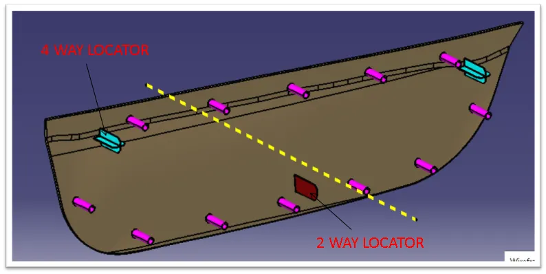
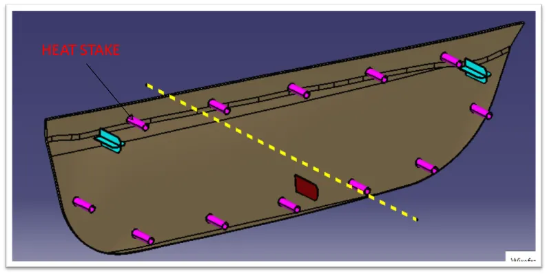
Creating the Heat Stakes and the Locators considering the design rules mentioned in the video for the door applique.
The Thickness of the component is considered as 2.5 mm
INTRODUCTION:
DRAFT ANALYSIS:
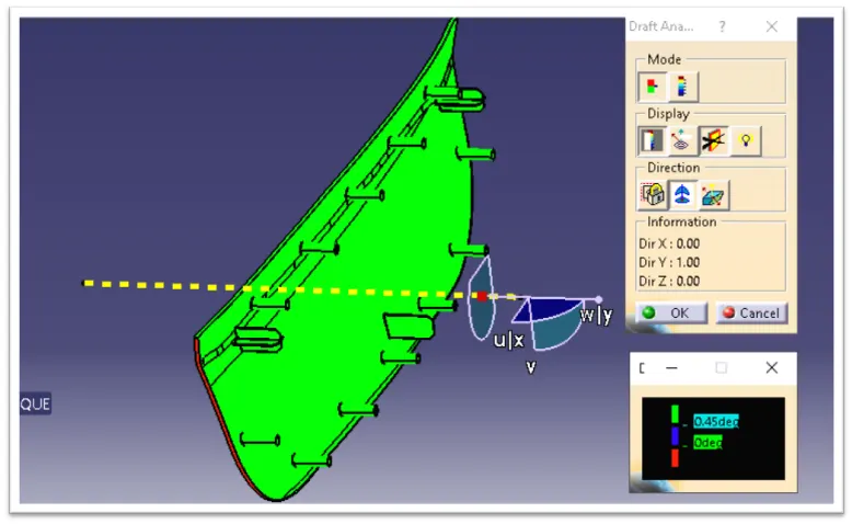
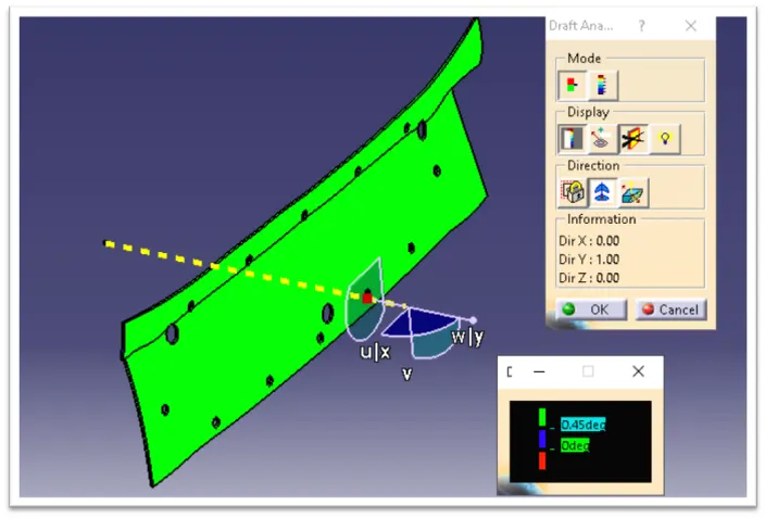
- Draft analysis is performed based on color ranges identifying zones on the analyzed element where the deviation from the draft direction at any point, corresponds to specified values. Draft is required on all parts in the direction of mold movement in order to allow parts to release or eject from the properly.
- Draft is the angle in which the parts is tapered to allow it to release. As the part cools, it tends to want to shrink to the core side of the mold. The draft allows the parts to release easily from the mold without creating friction between the surface of component and the core and cavity plates.
- Most applications require minimum draft angle of around 5o to 1o, however 3o draft angles are widely accepted for cost saving purpose. 7o draft angles are given to textured surface like instrument panels. Minimum possible draft angles are given to screw bosses, ribs and stiffeners due to their critical nature.
CLASS A SURFACE:
In automotive design, a class A surface is any of a set of freeform surfaces of high efficiency and quality. Class A surfacing is done using computer-aided industrial design applications. Class A surface modelers are also called "digital sculptors" in the industry. Industrial designers develop their design styling through the A-Surface, the physical surface the end user can feel, touch, see etc.
Design check on Class A Surface:
- After reciving class a for the fan cover check for the connectivity of the surface on it. If there is any disconnectivity, use join operation, boundary operation and disassemble.
Join operation:
- Go to join command to join the disconnectivity of the surfaces.
- When there not connected, after reciving Class A, delete only the boundary operation and disassemble, When there are connected delete join operation, boundary operation and disassemble after the check. The check is over if any disconnectivity do not arise.
TOOLING AXIS:
It is the dirction in which the mold open or core & cavity open. Part drafts are given along this axis.
Tooling operation:
- To deside the tooling axis, the component should be completely clearing the Tooling axis in the given specific direction. Analysis the components, the fan cover components has two walls.
- First one visually check. We can check, which one is possible to Tooling Direction. We can check al x, y & z direcion. If you have hole, what it will happen, you haven separate side core for specific hole. In this draft analysis of fan cover Z – direction is the possible of Tooling direction.
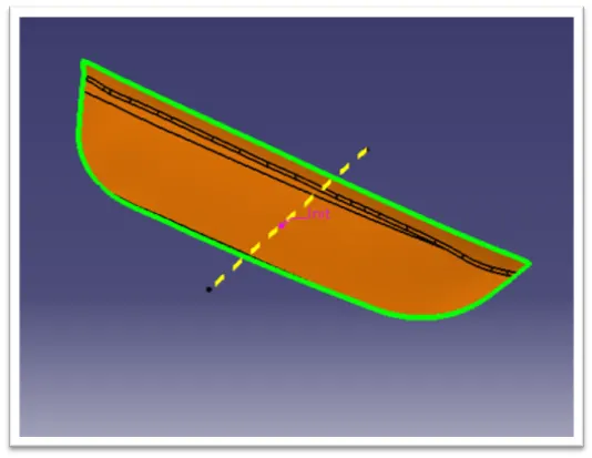
PUBLICATION
- Publish it using INSERT – PUBLICATION – Select the Class A Surface & Tooling Axis.
- To make sure that easily visual to work on draft.
DRAFT ANALYSIS:
Click the Insert - Analysis -- (Feature) Draft Analysis icon
If material is not on there will be a warning message is shown and then we need to select the material
The Draft Analysis dialog box is displayed. it gives information on the display (color scale), the draft direction and the direction values
DEVELOPMENT OF CLASS B SURFACE
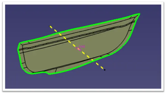
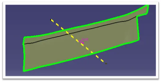
Class B surface is created by extracting each walls and untrimmed walls extrapolating the walls and then trimming the extra surfaces and offsetting it to certain value based upon the thickness of the component where it is 2.5mm. the offset surface will be the B- surface.
DEVELOPMENT OF CLASS C SURFACE
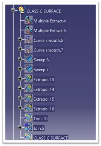
- This surface is obtained by sweeping the boundaries of the Class A surface along the Tooling Axis direction, It connects A and B Surface.
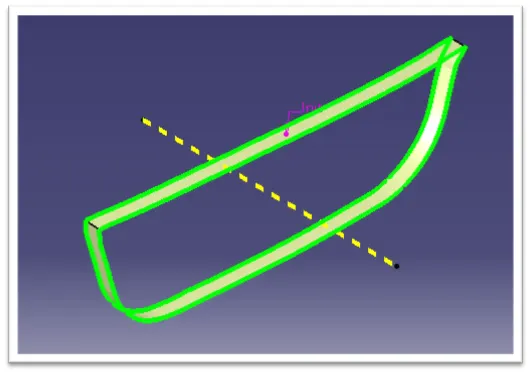
- Using b and C surface a closed surface is formed by trimming the extra surface
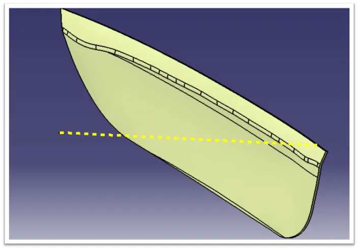
- The final trim part is converted into a solid component using closed surface command
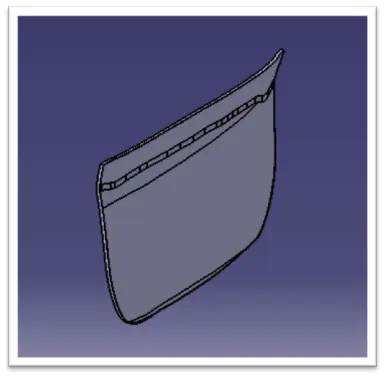
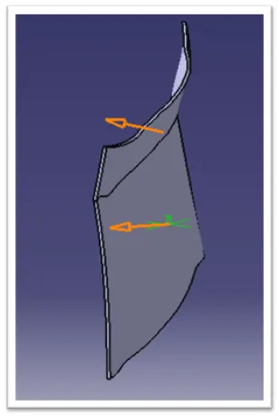
The Heat stake and Locators to the Door Applique trims:
3-2-1 PRINCIPLE:
- It is also known as a six pin or six point location principle. In this the three adjacent locating surface of the blank (workpiece) are resting against 3,2 and 1 pin respectively, which prevent 9 degrees of freedom
- The rest three degrees of freedom are arrested by three external forces usually provided directly by clamping.
Generally a body has 12 degrees of freedom as shown this diagram below
Methodology of 3-2-1 principle:
For this refer the below figure:
- The workpiece is resting on three pins or locators l1,l2, and l3 which are inserted in the base of the fixed body.
- The workpiece cannot rotate about the axes xx and yy and also cannot move downward.
- In this way, the five degrees of freedom 1,2,3,4 and 5 have been arrested.
- Two pins l4 and l5 are inserted in the fixed body, in a plane perpendicular to the plane containing pins l1,l2 & l3.
- Now the workpiece cannot rotate about the z- axis and also it cannot move towards the left.
- Hence the addition of pins l4 and l5 restrict three more degrees of freedom, namely 6,7 and 8.
- Another pin l6 in the second vertical face of the fixed body arrests degree of freedom 9.
The above method of locating a workpiece is called the 3-2-1 principle.
4-way and 2-way locators:
- 4-way means you prevent movement at 2 axis (+x,-x,+y and –y) on the plane.
- 2-way means you prevent movement only at 1 axis on the plane.
HEAT STAKING:
- Thermal heat staking ia an assembly method that uses the controlled melting and reforming of a plastic stud or boss to capture or lock another plastic or metal component of an assembly in plane.
- The plastic stud protrudes through a hole in the component to be locked in place
- The heated thermal tip contacts the top of the stud which melts and fills the volume of the tip cavity to produce a head locking the component in place.
ADVANTAGES:
- Simplification of machinery
- Reduced cost of machinery
- Multiple fastening points
- Allows higher density of welds compared to hot air cold form or ultrasonic welding.
LOCATORS AND HEAT STAKES DESIGN PROCEDURE:
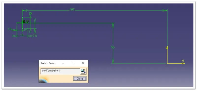
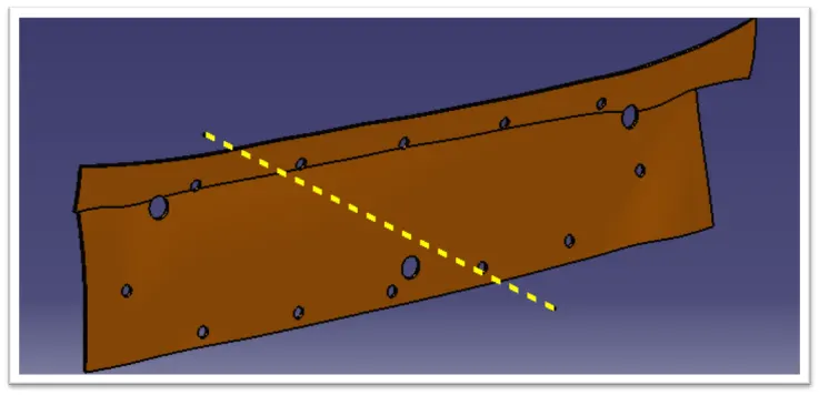
HEAT STAKES COUNTER CLEARANCE
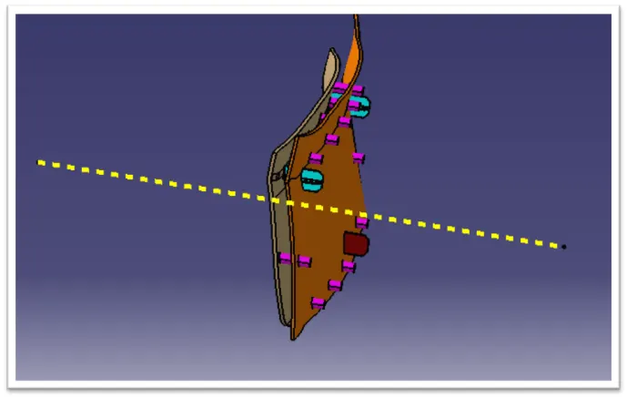
Driver door RH applique plastic component with locators and heat stakes:
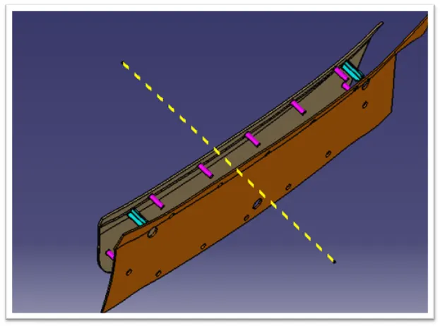
DOOR APPLIQUE:
ISOMETRIC VIEW
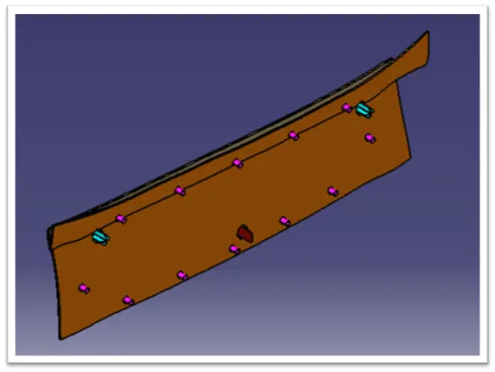
SIDE VIEW
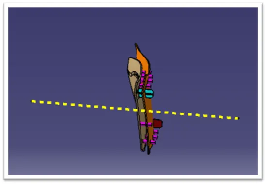
TOP VIEW
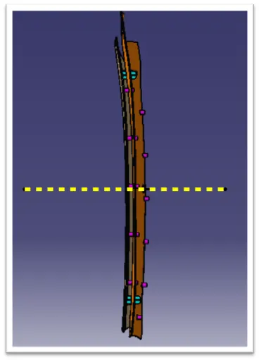
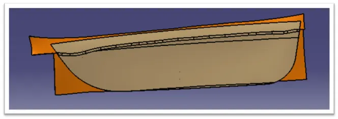
RARE VIEW
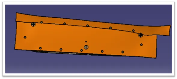
FRONT VIEW
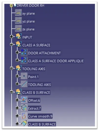
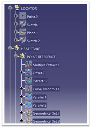
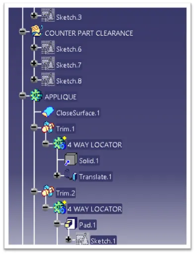
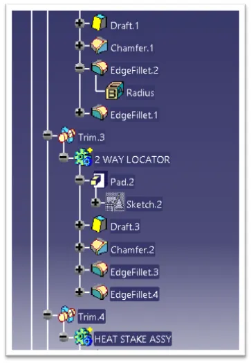
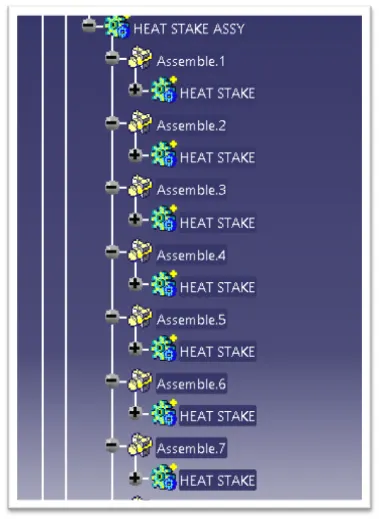
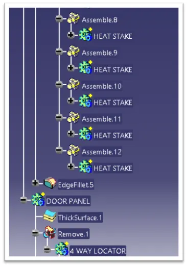
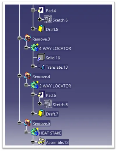
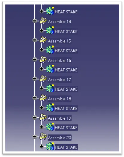
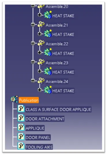
TREE STRUCTURE:
DRAFT ANALYSIS:
CONCLUSION:
- Thus the door applique design has been developed by using given class a surface.
- 2 and 4 way locators has been designed in order to fix the position of the applique with the mating door panel and also designed the heat stakes which used to fix the component with the mating panel by melting.