Week 9 - Project 1 - Door Applique Design with Engineering Features
OBJECTIVE:
To create the door applique from the given A surface to solid by creating B and C surface.Assemble the created component with the simplified door surface.
B SURFACE:
The b surface is created with refernce to the A surface and make sure the two surfaces do not self intersect,it may create a error in trimming operation.The surface must be offseted to a distance of 2.5mm from the A surface.
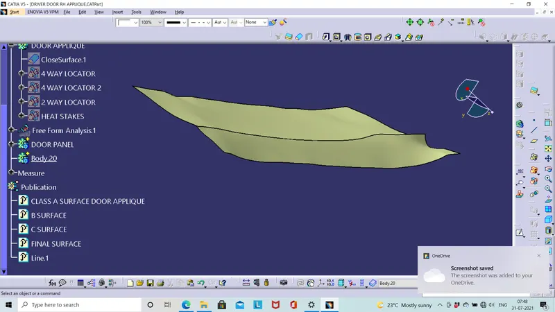
The tooling axis is created in the surface from the point created.
C SURFACE:
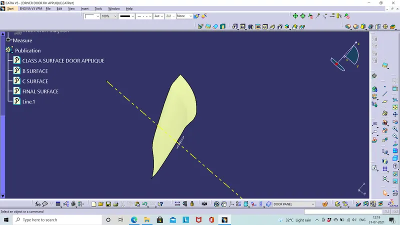
The C surface is created with the boundary extracted from the A surface and sweep them with the draft direction .C surface and A surface are joined together without any gap.
FINAL SURFACE OF DOOR APPLIQUE:
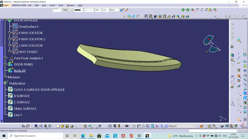
The b surface and the join(A & C surface) is trimmed to get the desired final component with a thickness of 2.5 mm and make solid using close feature. Make sure there is no open boundary in the component before closing the feature.
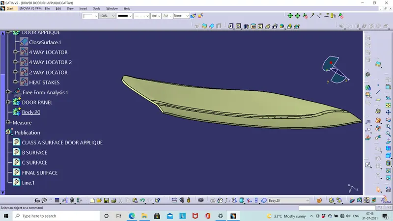
DOOR APPLIQUE:
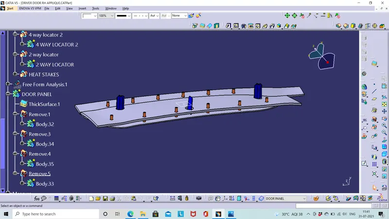
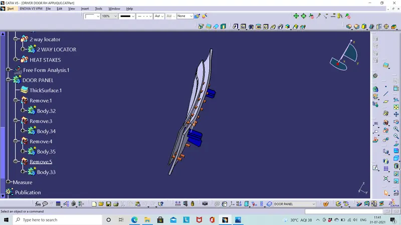
The door applique is created,following this we have to fix the component to the door .For that we have to arrest its degree of freedom except its way to fixing direction.We use two way locator, four way locator and heat stakes to control the degree of freedom. 3-2-1 principle is used to arrest all six degree of the component.It is used to accurately position the component.
Heat staking or Thermal staking are the process of joining two parts through welding heated thermal tip is used for joining.It is more effecient and cost reduction process. It is a controlled melting process.
DEGREE OF FREEDOM: There are 12 degrees of freedom in the applique(6 translation,6 rotational)
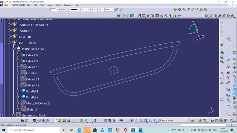
This image shows the parallel curve(the curve one inside) where we place the heat stakes in the component.
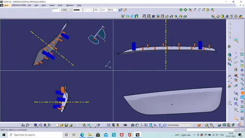
VARIOUS VIEWS:
The locators (both 4 way and 2 way)are created on the door applique.All the locators should be of same height with a tolerance of +/- 1mm.The locators should be drafted and filleted.The minimum draft angle is 0.5 degree which is used for ribs,the wall thickness should be 40% of wall thickness of the component.
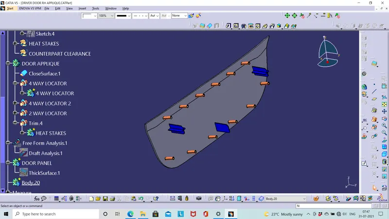
We can use screw boss,clipping for joining of two components here we use heat stakes which is cost effecient.The heat stakes are drawn in the parallel curve,it should not interfere with locators in the surface.
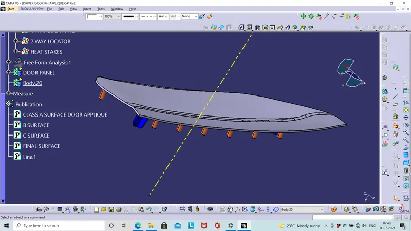
A clearance should be given in the assembling body for the locators,so it will be easy for assembling.The clearance should be circular,for locators clearance recommended is 0.05mm per side and for thermal stakes it is 0.5mm per side.
MULTI VIEW:
DRAFT ANALYSIS:
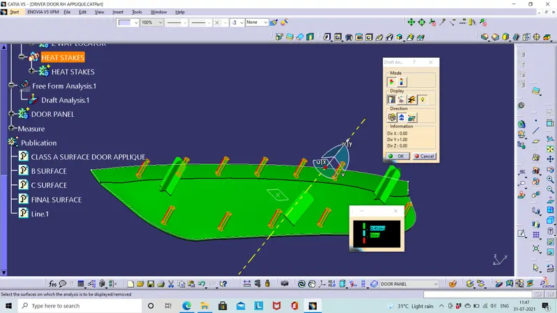
The A surface is draft analysed with toolong axis,the minimum draft angle should be 3 deg. This image shows the draft analysis of the component.
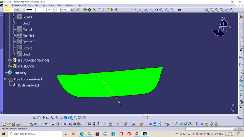
The draft analysis on the locator also to be done since it is drafted for 0.5 deg the draft angle for analysis can be 0.45 deg to avoid the deviations.
REAL TIME DOOR APPLIQUE:
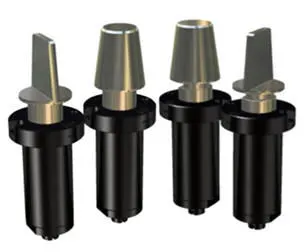
This is the door applique of a car (ford).Here there is a two 4 waay locator and one 2 way locator at the bottom if you look closely. The locators are molded along the component.The other image shows the locator manufactured seperately.
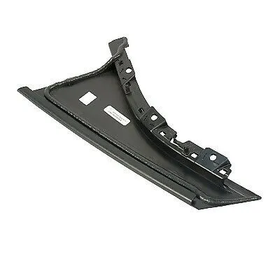 Four Way and Two Way Locators (kintocanada.com)