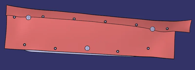
Week 9 - Project 1 - Door Applique Design with Engineering Features
Week 9 - Project 1 - Door Applique Design with Engineering Features
Aim:
- Creation of proper tooling axis considering the required draft angle of the component
- Performing draft analysis on the given Class A Surface and then final component
- Creation of Class B and Class C Surface
- Adding the Heat stake and locators to the Door Applique trims
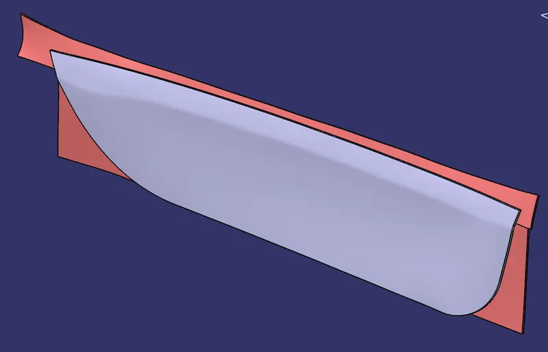
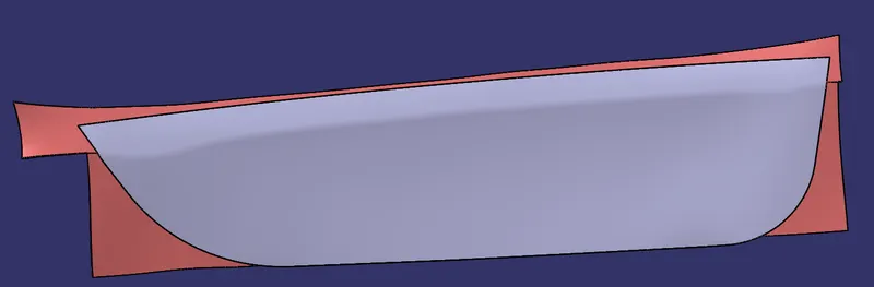
Given Input: Door Applique surface and Door Panel mounting surface
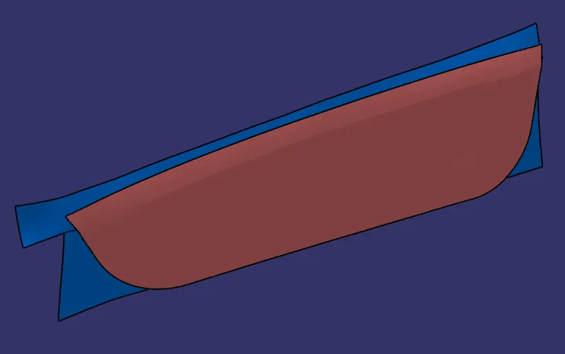
Tooling Axis Creation: Tooling axis is created considering the required draft and ejection diresction and the assembly direction.

Class A Draft analysis: Draft analysis on Class A Surface using the created tooling direction meets the requirements.
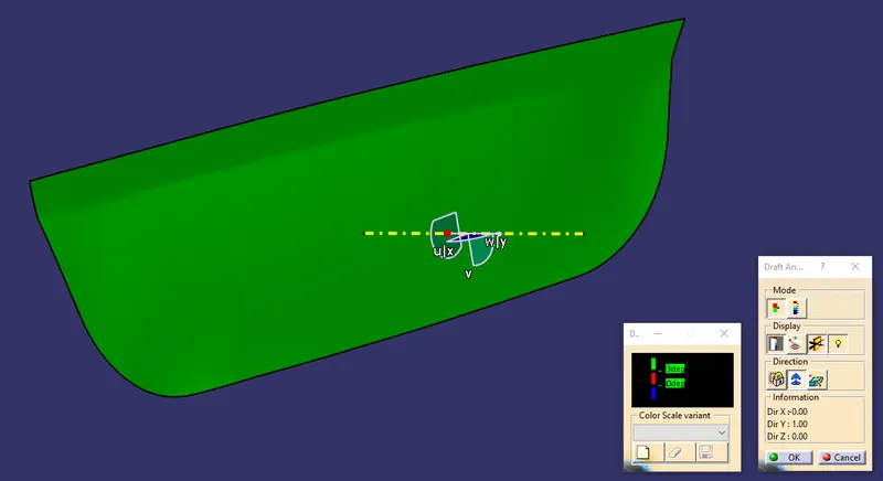
Creation of Class B and C Surfaces: Class B surface is created by offsetting the Class A Surface and extrapolating it outwards.
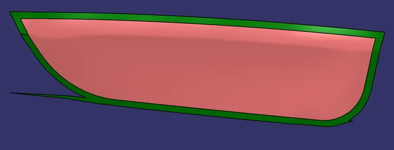
For C Surface, a boundary is created on the Class A Surface and then this boundary is swept along the tooling direction
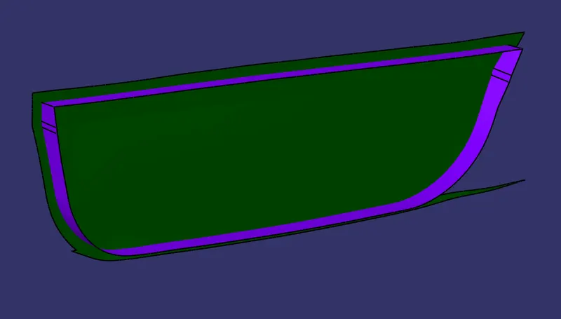
Now the B and C surfaces are trimmed to each other and then the trim is joined with the Class A Surface.
Now the joined ABC Surface is made into a solid using the Close Surface command.
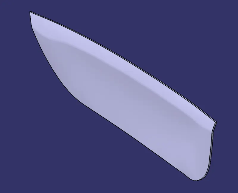
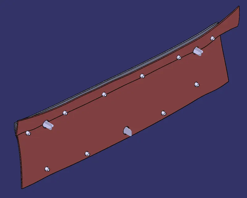
Adding Locators
- Points are created where loacators need to be placed.
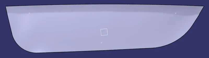
- Positioned sketch is made at one of these points as shown below.
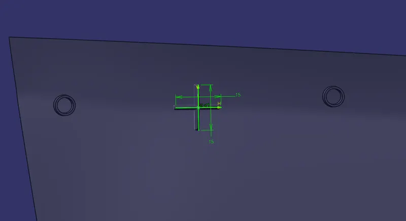
- Now a Pad is created using this sketch in a new body. The thickness if this Pad should be 1.3mm which is about 50% of the wall thickness
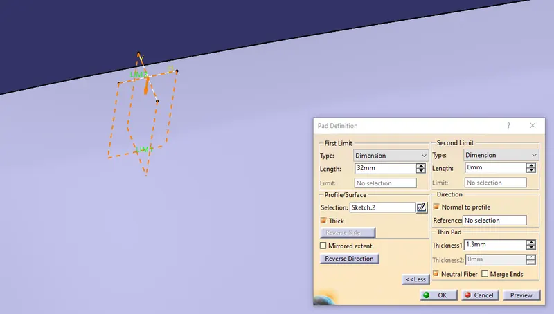
- Draft of 0.5 Degrees is provided on all the required faces.
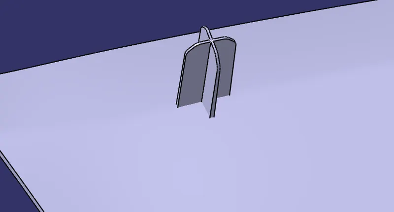
- This 4 way locator is translated by point to point method to the other side.
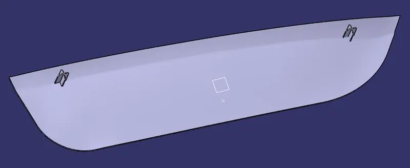
- Similarly a 2 way locator is made on the lower side.
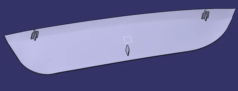
- These locators are now union trimmed with the main body.
Adding Heat Stakes
- Paralled curve of 15mm is made to the boundary and points are created in this curve using points repetition.
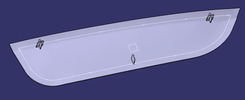
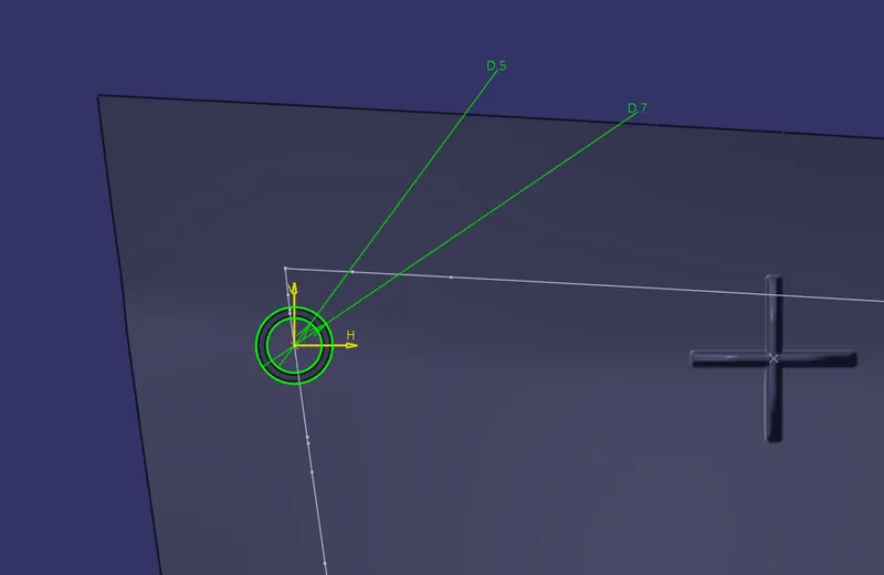
- A positioned sketch is made at one of these points as shown below.
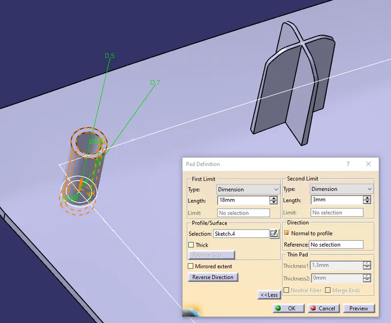
- This sketch is padded as shown below. The height of the heat stake should be less than the locator for proper location. Draft is added to all the required faces.
- This heat stake is copied and translated to all the other points.
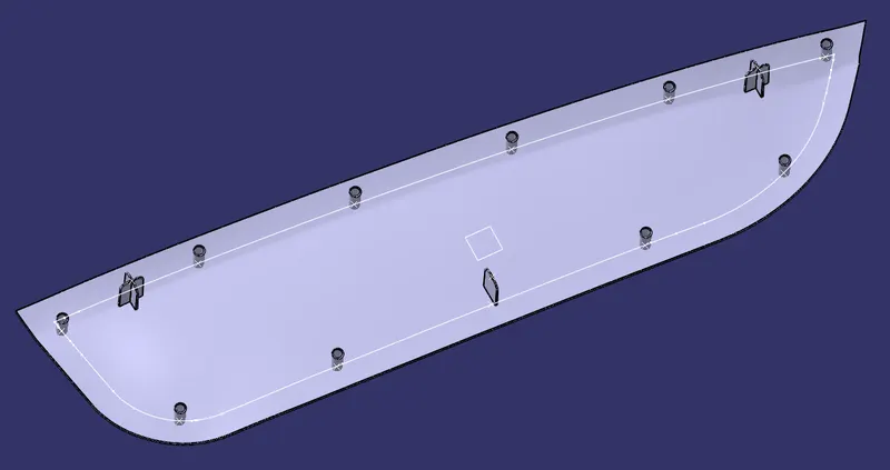
- Now all these heat stakes are assembled into one body and union trimmed with the main body. Fillets of 0.3mm are added to the sharp corners.
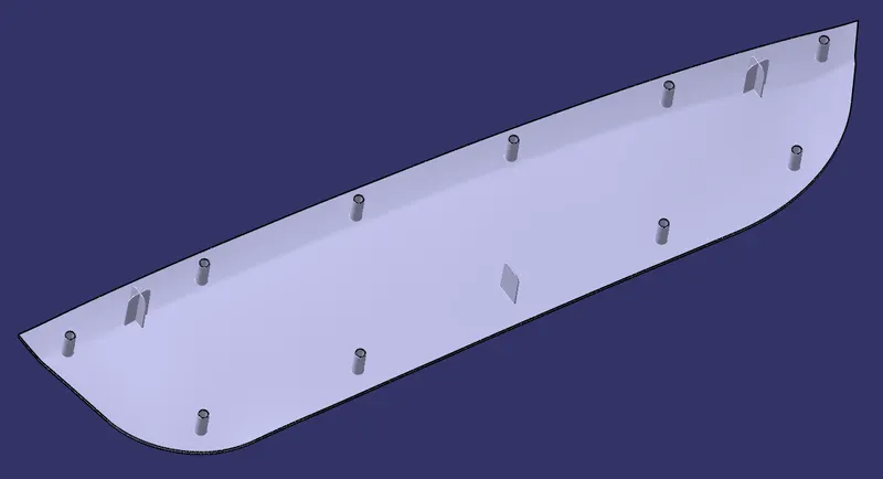
Adding Holes to the Door Panel mounting face
Positioned sketches are made for the Locator and Heat stake holes. The locator holes need to have a clearance of 0.1mm on either side, while the Heat Stake holes need a clearance of 0.5mm on either side.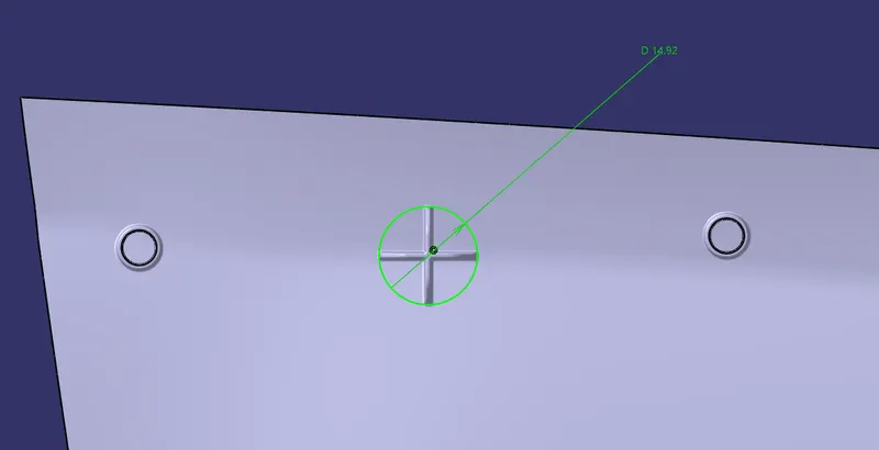
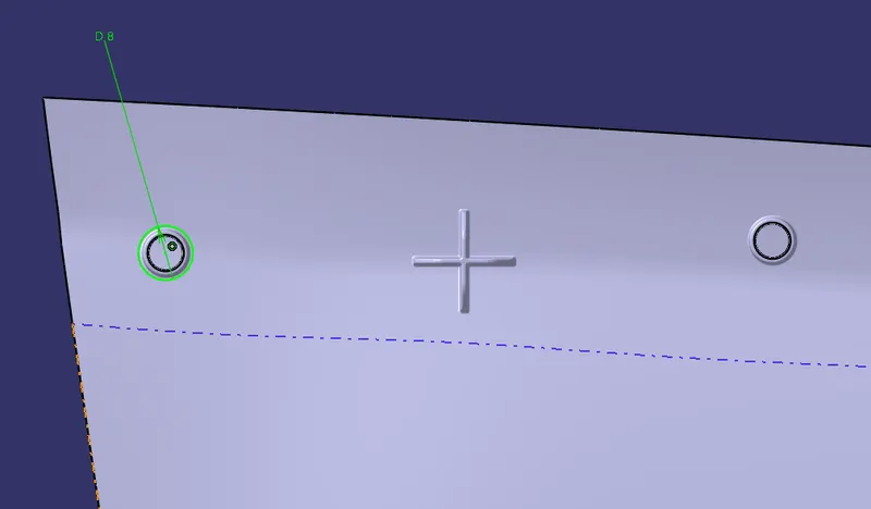
These sketches are padded in a new body. This body is copied and translated to all the other points.
Now these bodies are assembled into one body and removed from the main body.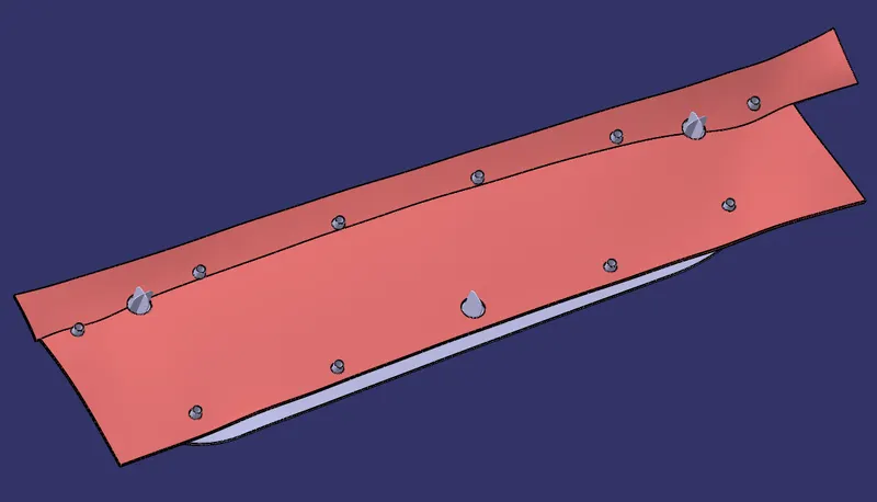
Draft analysis on the final component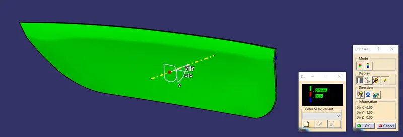
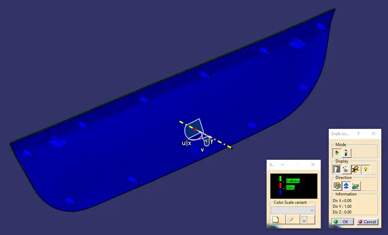
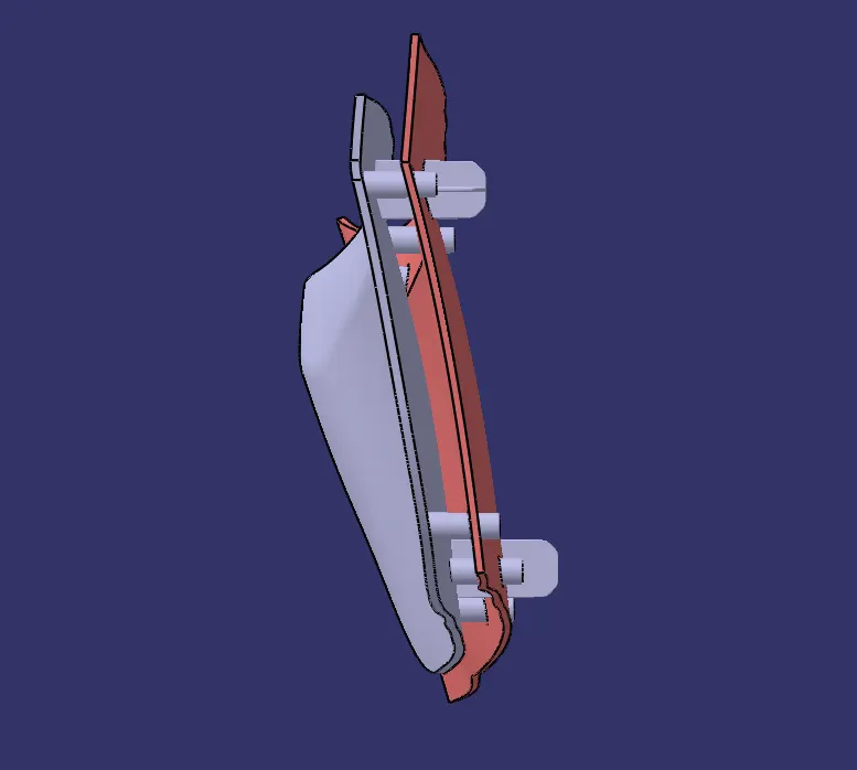
Screenshots from various orientations