Week 8 - Challenge 2 - Base Bracket Design
Week 8 - Challenge 2 - Base Bracket Design
Aim:
- To create proper tooling axis considering the required draft angle of a component.
- To perform draft analysis on the given Class A Surface.
- To create Class B and Class C Surface and make a solid body.
- To perform draft analysis on the final component
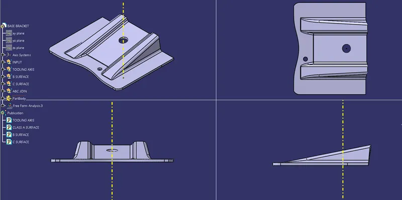
Given Input: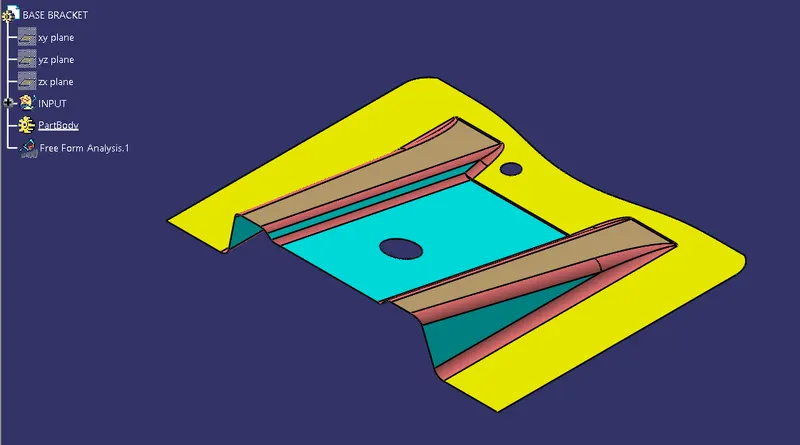
Tooling Axis creation:
- The first step is to check the class A surface using either the join command to check for any connexity errors or the boundary command to check if there are any discontinuities.
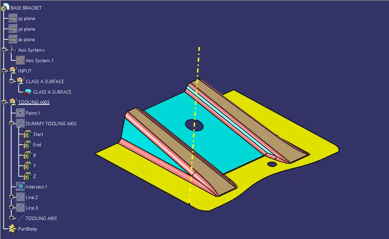
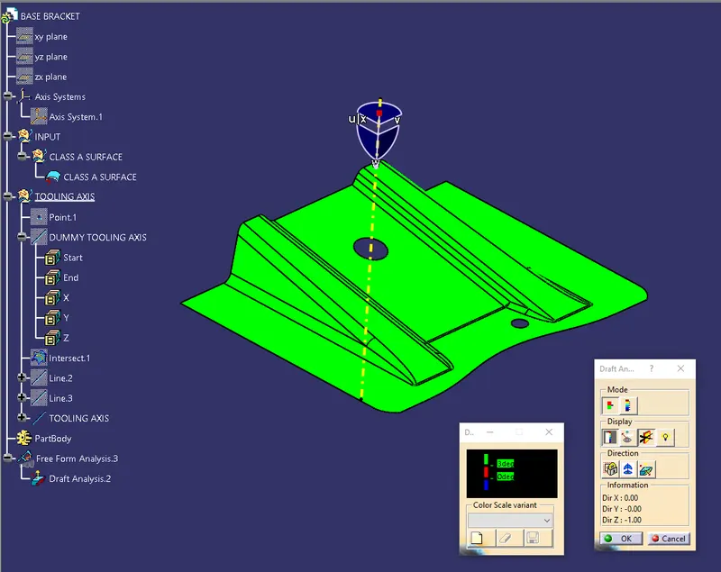
- Then the model is visually inspected to determine the best posssible tooling axis and a dummy tooling axis is created.
- In this case a point is created at the center of the large hole and line is drawn from the hole in the Z direction using Point-Direction option in the Line Command
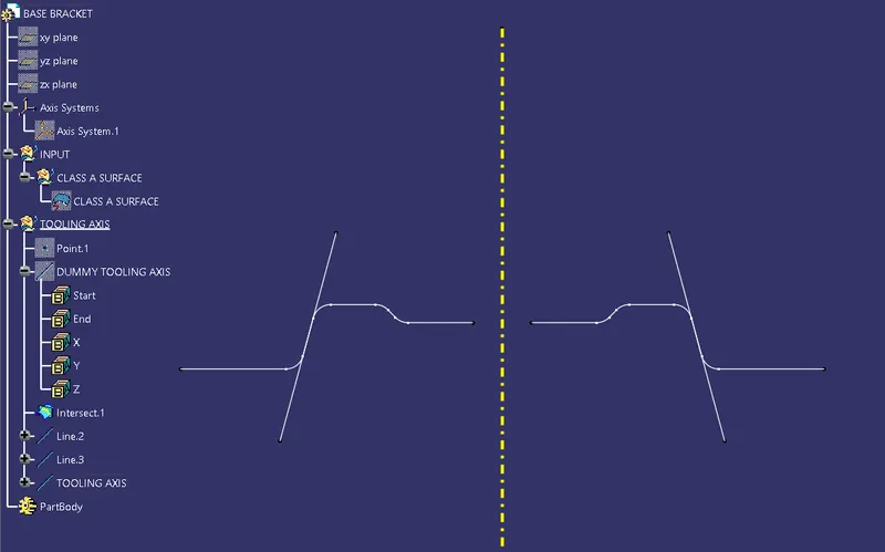
- Then an axis system is created at this point and an intersection is created between this class A surface and YZ Plane of the newly createed axis system.
- Tapered surfaces in this intesect is examined and a bisector line is created between the surfaces that can cause problems while ejection.
- This Bisector line is the Tooling Axis.
Draft Analysis:
- Draft analysis tool can be brought up from Insert > Analysis > Feature Draft Analysis
- The compass is dragged and dropped on to the tooling axis.
- The required angle of draft to be checked can be enetered in the color scale.
- If the surface is completely blue then the draft direction should be inversed.
- It is ensured that the entire surface is green which shows that the part clears in the tooling axis.
B Surface Creation
- The surfaces present in the Class A Input need to be need to offset excluding the fillets. The offset value should be the thickness of the part.
- In this case, at first, one of the ribs in the part is taken. The surfaces of the rib are extracted and untrimmed.
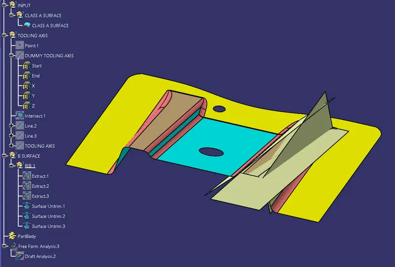
- Then the untrimmed surfaces are extrapolated on all sides.
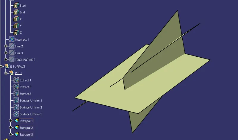
- Now they are trimmed to each other. This gives us the rib surfaces without the fillets.
- Now this surface is offset to the part thickness, which in this case is 2.5mm.
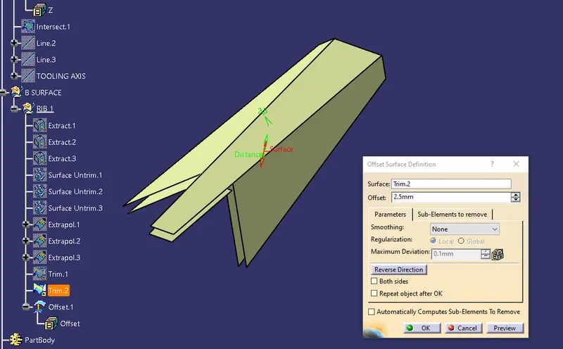
- The same procedure is repeated for the other rib also
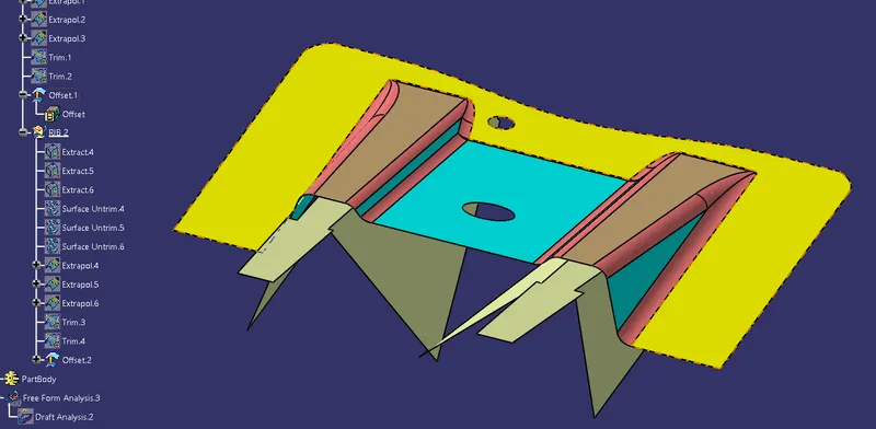
- Now the remaining base surfaces (Yellow and Blue surface with hole) are extracted, untrimmed and offset.
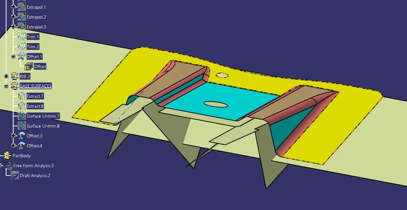
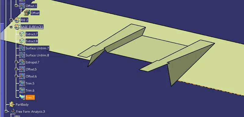
- Now these surfaces are trimmed off with the rib surfaces
- Finally fillets are added to this B Surface. The fillet value for the B surface is determined by measuring the fillet value of the Class A surface and then calculating the offset fillet from it by adding or subtracting (based on whether the fillet is external or internal) the part thickness to the fillet value.
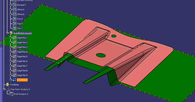
- The B surface is given a different colour to distinctively identify it
C Surface Creation
- C Surface is the connecting surface between the Class A and B Surfaces.
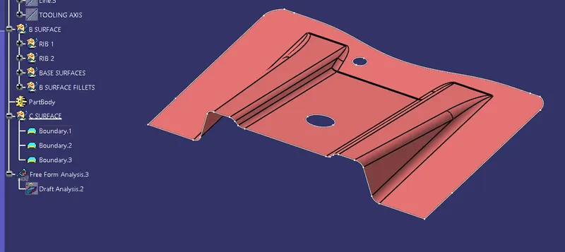
- First step is to create a boundary around the Class A surface and the Holes.
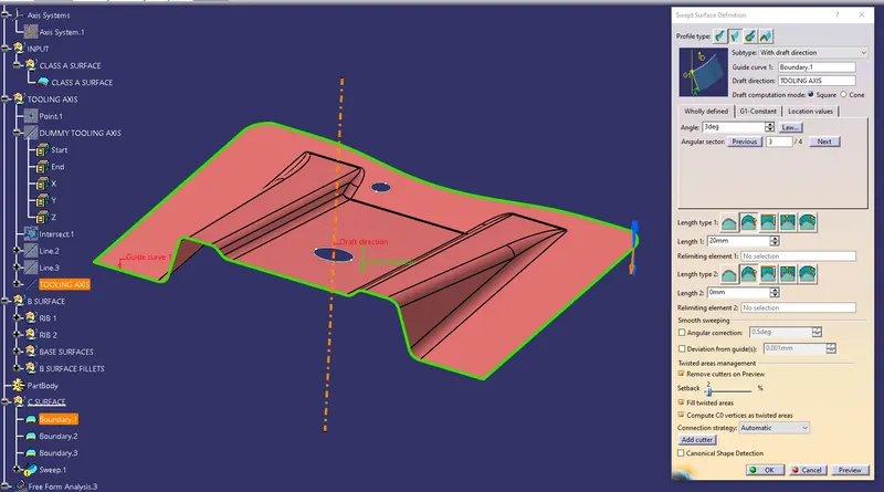
- Now using the Sweep command and having the Profile Type as Line and the Subtype as With draft direction create a sweep using the boundary as the Guide Curve and the Tooling Axis as the Draft direction with a Draft angle of 3 degrees and the arrow pointing downwards.
- Using this same procedure C Surface is created for both the holes.
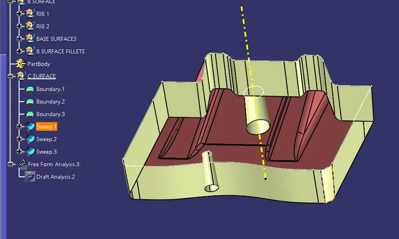
- The C Surface is given a distinct colour to make is easy to identify
ABC Join:
- Class A surface and B Surface are joined using the Join command
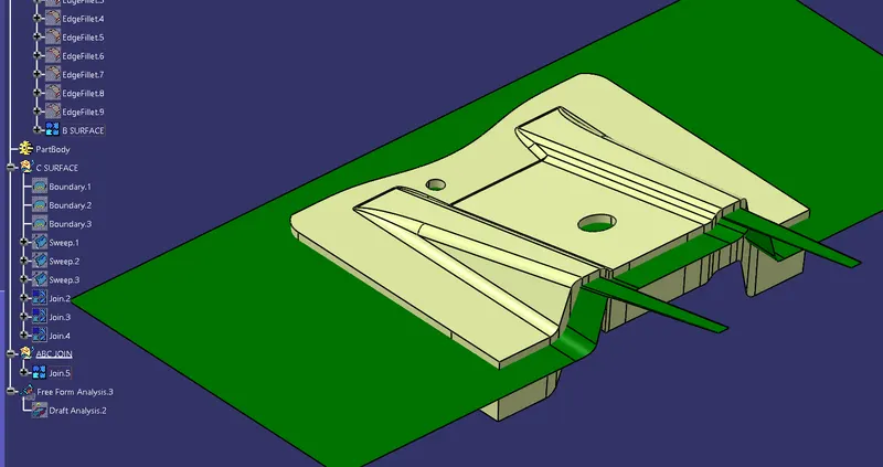
- The A and C join surface is now trimmed to the B Surface
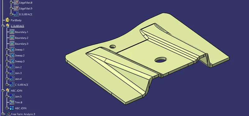
Creating a Solid Body
The ABC join surface is made into a solid body by using the Close Surface command. This close surface is created in the Part Body.
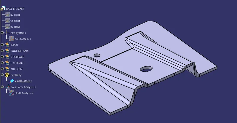
Draft analysis on the final body
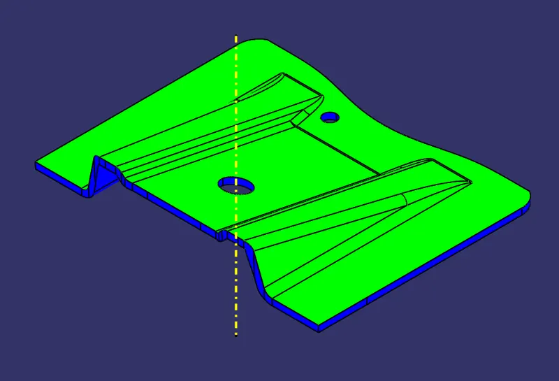
Draft analysis on the final body shows that the Class A surface (Green) will be formed by the Cavity while the B and C surface (Blue) will be formed by the core.
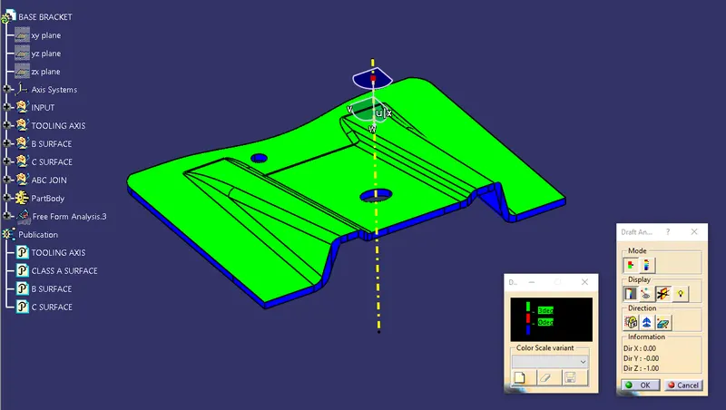
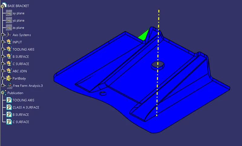
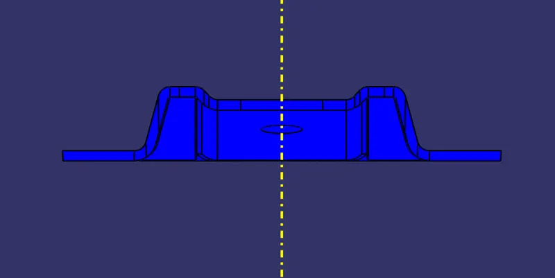
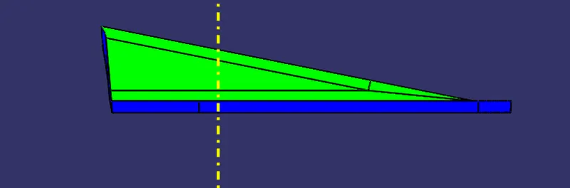
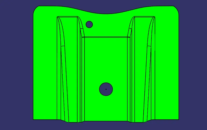
Screenshots of various views