Week 8 - Challenge 1 - Draft Analysis on a Fan Cover
Week 8 - Challenge 1 - Draft Analysis on a Fan Cover
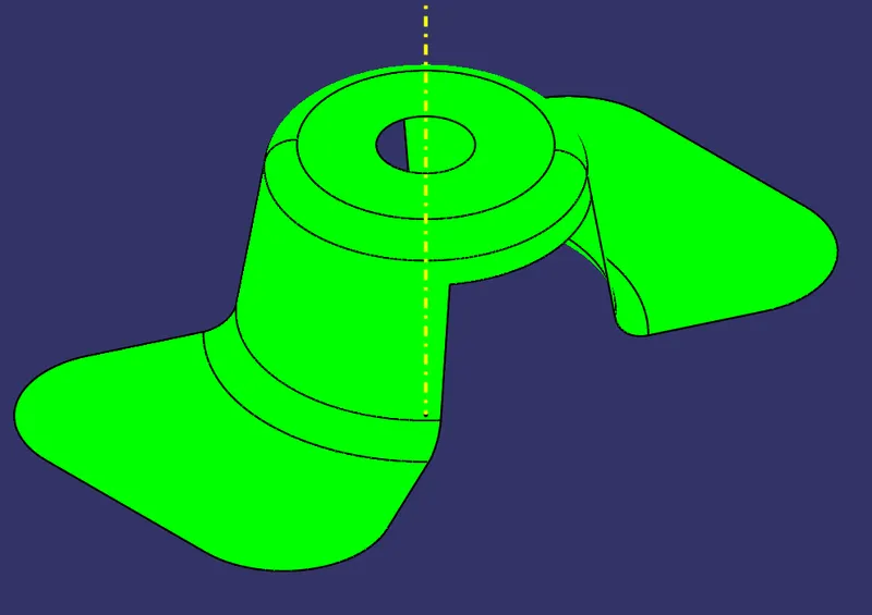
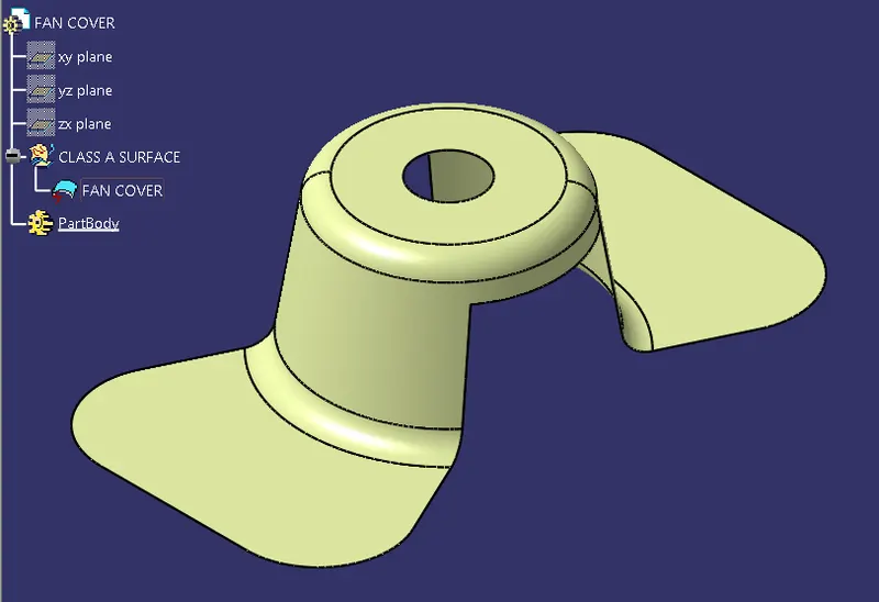
Aim: To create a tooling direction for the given Class A surface and to perform draft analysis on this surface using the created tooling direction.
Input Given:
What is Draft and why is needed for Injection moulded plastic parts?
A Draft is an angle provided to the mould wall to facilitate easy removal of the moulded parts from the mould. Plastic parts that are designed for injection moulding must have draft on all surfaces that are perpendicular to the parting line of mould.
After the molten plastic is injected into the mould, the mould is cooled to solidify the component, during which the part tends to shrink around the core and stick to the core. In order to remove this moulded part easily, adequate taper must be provided both in the core and cavity of the mould. Usually moulded parts require about 0.5 Degree to 3 Degree Draft. Surface with grain or texture may require upto 7 Degree Draft.
PROCEDURE:
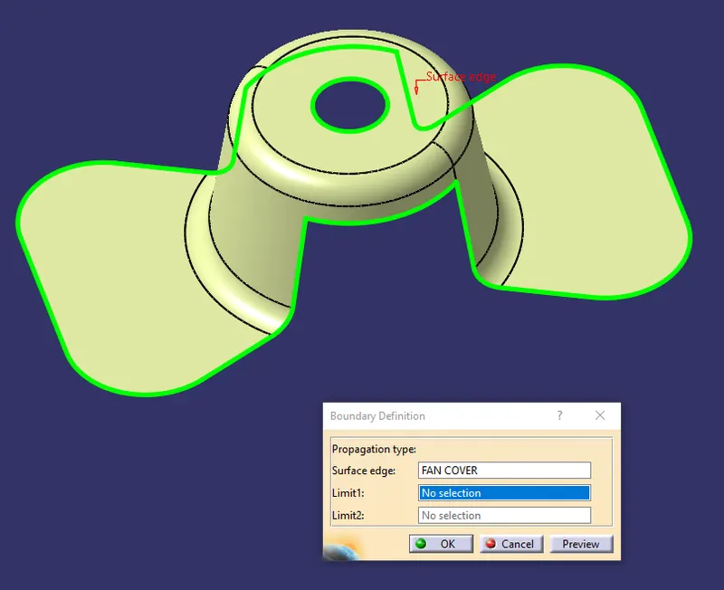
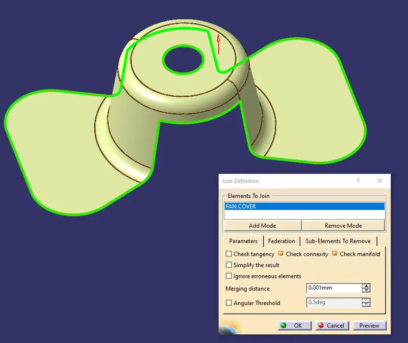
- Ensure Class A surface connectivity: The first step is to ensure that the Class A surface is free from discontinuitites. This can be done by either using the Join command to check for connexity error or the boundary command to check to surface boundaries.
- Create a dummy tooling axis: The model is first visually checked to find the best possible tooling direction. Then a dummy tooling axis is created which will act as a guide or reference to create the actual tooling direction.
In this case the Z Direction appears most probable since it clears the taper faces as well as the hole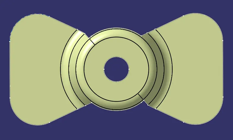
A point is created at the centre of the hole and an axis system is created at this point. Ensure this axis system is not current.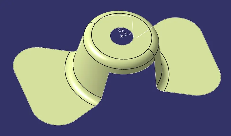
Create intersect of the XZ plane of the axis system with this Class A Surface. Now create a line in the Z Direction from the centre of the hole. This line is for the dummy tooling axis.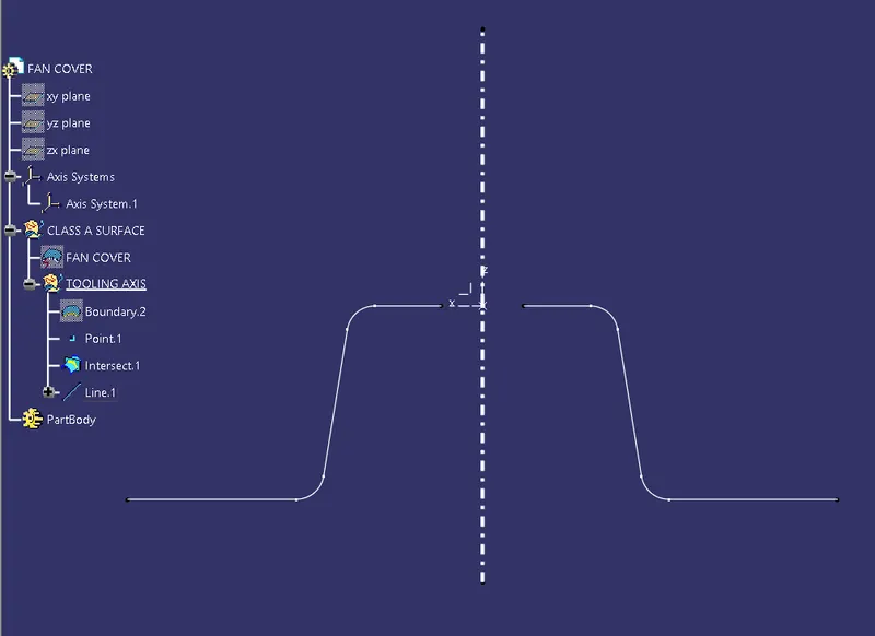
- Create actual tooling axis: After creating the dummy tooling axis, the intersect should be checked to see which of the lines can probably cause problems during ejecting. In this case, the two tapered lines on either side.
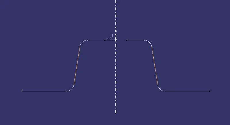
Create lines using these tapered lines using the Point-Point option in the line command. Then a line is created by bisecting these two newly created lines by using the Bisecting option in the line command.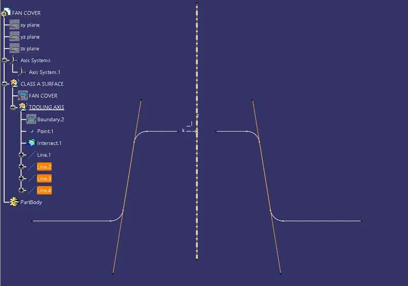
Similarly another intersect is created with the surface using the YZ plane of the axis system.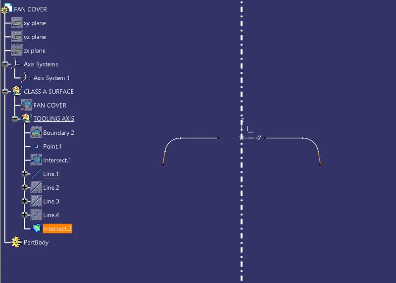
These two highlighted taper lines are used to create two lines which are then bisected by a bisector line.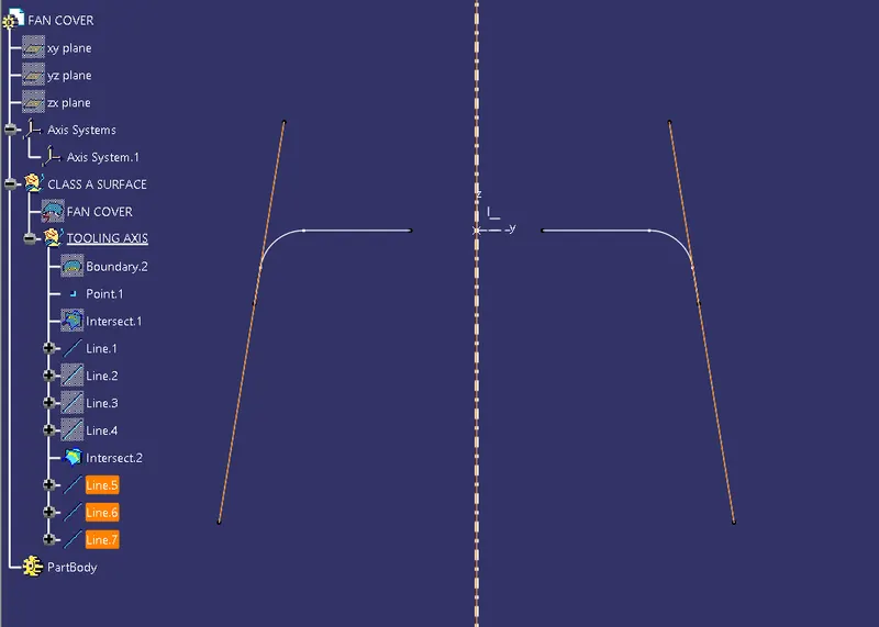
Now these bisectors are then bisected to create the final tooling diection.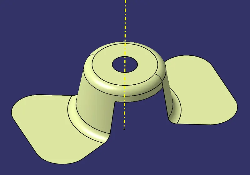
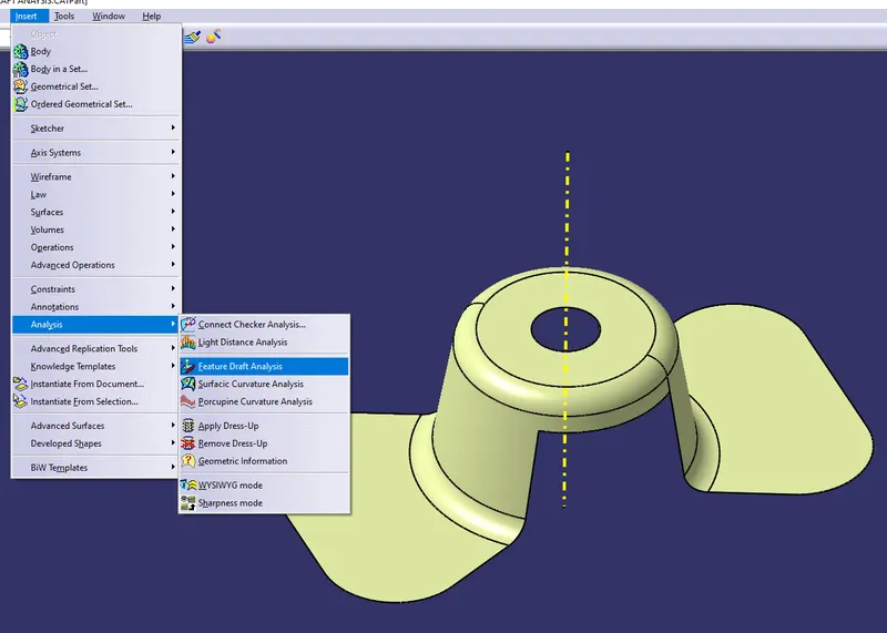
- Perform Draft analysis: Draft analysis is performed on this Class A Surface using the created tooling direction. The tool can be found in Insert > Analysis > Feature Draft Analysis.
Activate Material option in the customize view to see the draft analysis performed.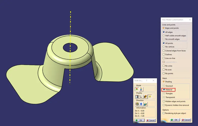
Now the compass is dragged and dropped on to the tooling direction line and then the compass option is activated from the direction pane of the Draft analysis window.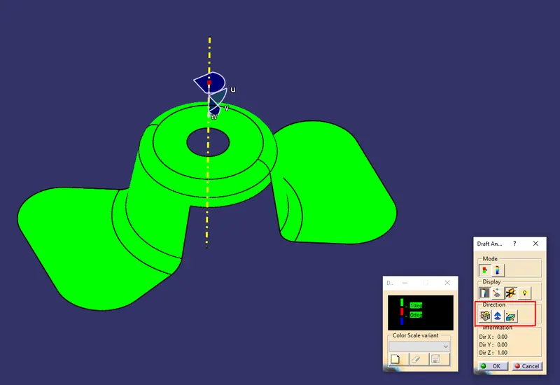
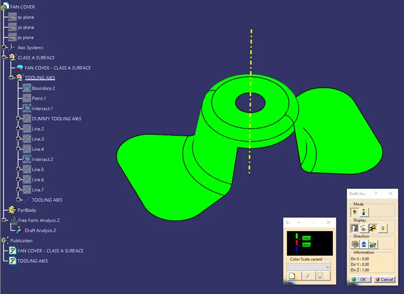
If the colour scale is not visible, it can be made visible clicking on the show or the color scale option from the Display pane. The required draft angle to check for can be adjusted in this color scale. In this case the angle is increased from 1 Degree to 3 Degrees. If the surface is shown completely in blue, Inverses the draft direction from the direction pane can be used and this will turn the surface to green.
If the surface is completely green it shows that the Class A surface completely clears the draft angle requirement.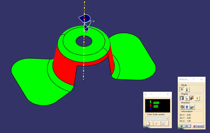
For example in this case if the draft requirement is 10 Degrees, then the value would be entered in the color scale and the surface that does not clear would show a Red surface as shown in this above image.
Switching on the full analysis mode enables use of two positive and negative angle values to check for Draft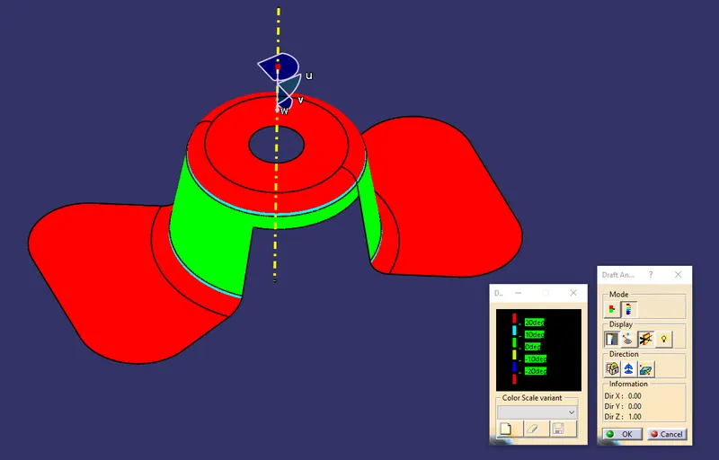
Analyses under the running point option shows the draft value at the point where the cursor is pointed.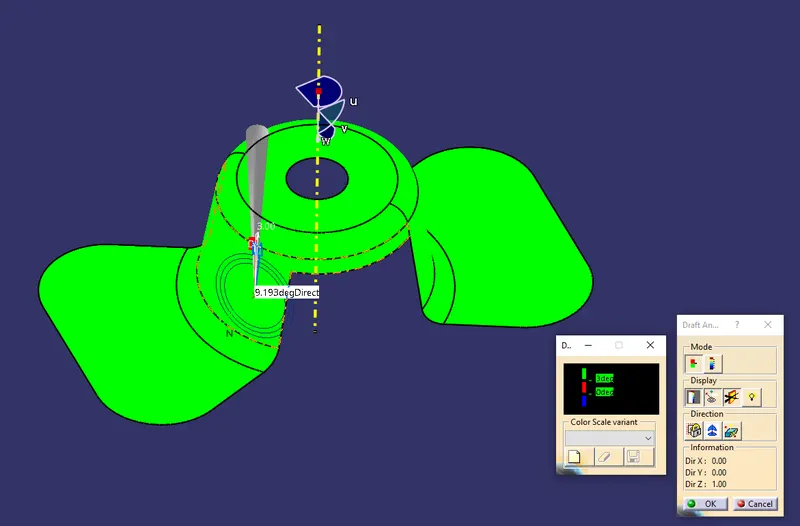
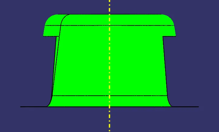
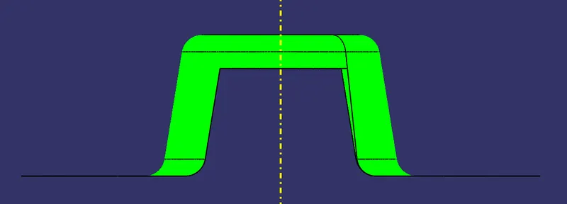
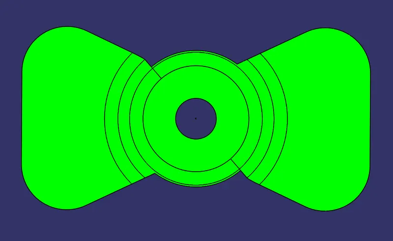
- Image of the complete Draft analysis
Various Views