Week 9 - Project 1 - Door Applique Design with Engineering Features
Aim: To create Door Applique Design with Engineering Features such as locaters, heat stakes etc. using the given door attachment reference surface and class-A surface of the door applique.
Given input:
- Class-A surface of the door applique
- Door attachment surface
Engineering features:
- The extensions on the plastic components on the Class-B side of the surface are called engineering features or B-side features.
- These features play an important role during the assembly of the sub components to the main component for example: map pocket, arm rest are assembled to the main door.
- Locaters, snap fits, dog house, screw boss, ribs, heat stakes etc. are some of the B-side features in automotive industry.
Door applique creation:
- Basic checks
- Check the connectivity of the class-A surface i.e. ensuring there are no surface gaps between the surfaces.
- This can be done either visually or manually by creating boundary of the component.
- The best way to know the connectivity and quality of the component is by checking how many domain boundaries have been generated using disassemble command.
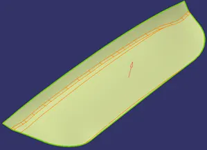
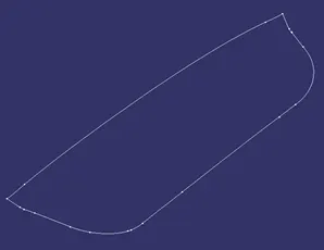
- The next step is to perform the draft analysis and for that we need the tooling axis
TOOLING AXIS:
- Tooling axis is a line in which the core and cavity opens and the component is ejected.
- Visually check which would be the best direction for the tooling axis.
- create line normal to the surface by creating a center point or an axis system on the base surface at the center.
- Perform the draft analysis of the given class-A surface to ensure the tooling direction is clearing the past and is easily removable from the mold with the help of color scale.
- Adjust the compass in small radius if the normal to the surface line is not clearing the part fully.
- After adjusting the compass to appropriate direction sop that the part is clearing everywhere lock the compass and change the normal to the surface line to the compass direction and consider it as the main tooling direction.
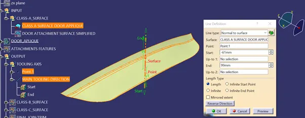
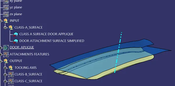
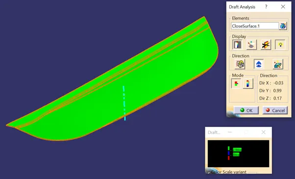
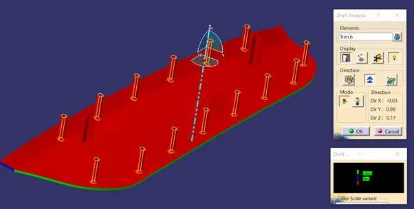
- DRAFT ANALYSIS: enables you to detect if the part you drafted will be easily removed.
- The visualization mode should be set to Shading with Edges in the View > Render Style command before performing draft analysis.
- Go to insert<analysis
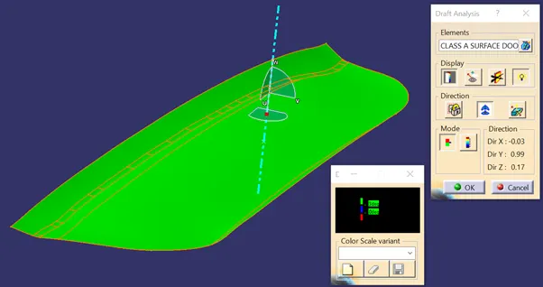
- The Draft Analysis dialog box is displayed. It gives information on the display (color scale), the draft direction and the direction values and identifying the maximum and minimum values for the analysis is displayed too.
- We will be using the default mode i.e. the quick mode as it simplifies the analysis in that .it displays only three color ranges.
- The maximum and minimum values for the analysis should be adjusted to 0 and 3 respectively as per the automotive industry as displayed below in the color range box.
- However, the maximum and minimum values will vary in cases of B-side features alone. Drag the compass by holding left mouse button on the red dot of the compass and place it on the main tooling axis randomly.
- Click the Compass icon
 to define the new current draft direction by aligning the compass exactly along the main tooling axis.
 - Click the Locked direction icon
 , for locking the direction of the tooling axis.
 - After locking the direction single click on any random area on the component or surface.
- The part will be shown colored either or mixture of the three colors (green, red, blue) on it.
- Three bands of color on the part in the below example will indicate
- Green: the area has draft angle more than 3 degrees
- Blue: the area has the draft angle between 0 to 3 degrees.
- Red: the area has draft angle below 0 degrees (negative draft angle)
- In the above door arm rest example, the green area indicates that the part has draft angle more than 3 degrees and easily clearing the mold, while blue area has the draft angle between 0 to 3 degrees
- Similarly repeat the draft analysis on the close surface (solid model).
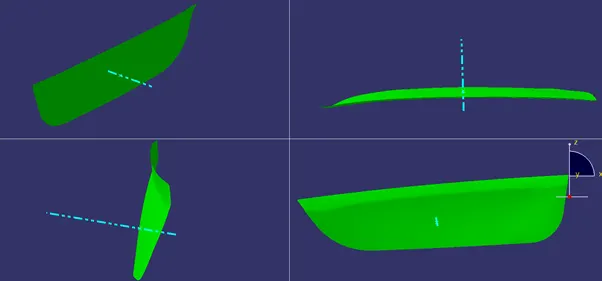
- CLASS-B SURFACE
- Since the surface is fully styling hence we can take the whole surface as a single patch of surface.
- The offset value for creating Class-B surfaces is provided i.e. 2.5mm.
- Extract >Untrim>extrapolate >offset the patches as divided.
- Use the various surface commands such as boundary, trim, split etc. available in the generative shape design and create the Class-B surface accordingly.
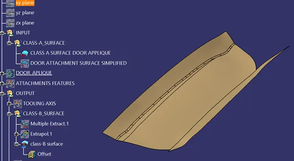
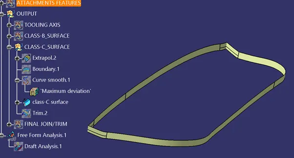
- CLASS-C SURFACE
- Create an exterior boundary or parting line for class-A surface.
- Using the available commands like sweep create the Class-C surface at an angle 3 degree to the tooling axis.
- Join the class-A surface and Class-C surface after by ensuring no gaps between them.
- Trim the Class-B surface after performing the above step and create a close surface.
- Cross check the final closed surface is completely closed ort not by using boundary command.
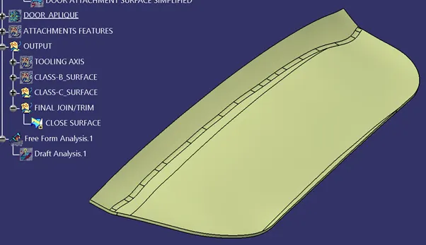
- CLOSE SURFACE
- Go to part workbench and create a solid body out of the close surface.
- And perform the draft analysis again.
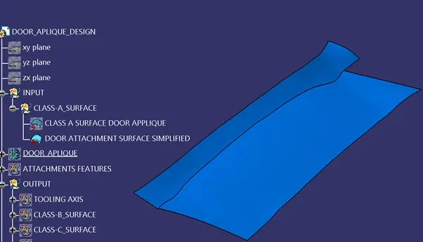
- DOOR ATTACHMENT PANEL: since the door attachment panel is used for reference we have made it as thick surface and given the thickness of 2.5mm accordingly.
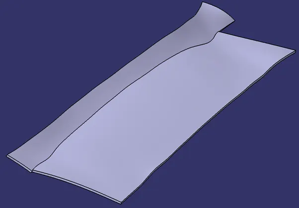
CEATION OF B-SIDE FEATURES
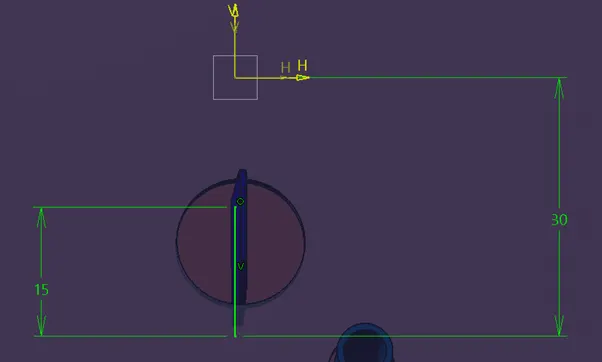
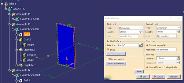
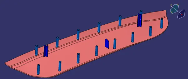
- LOCATERS: engineering features used during assembly of sub components to main component
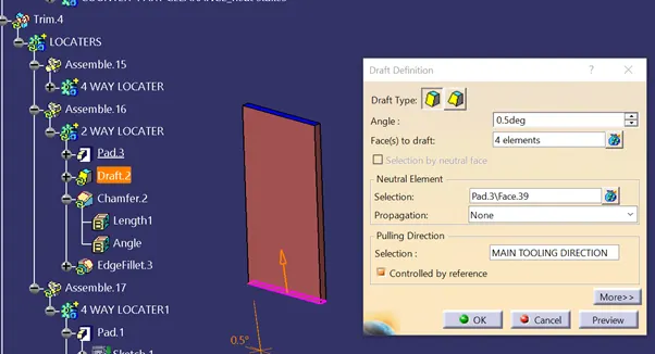
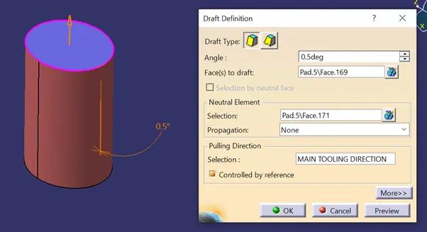
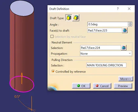
- Draft: 0.5 degree along main tooling direction
- Radius:0.1mm
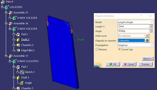
- Chamfer:3mm x 45 degree
- Height maintained: equivalent to 14 mm
- Thickness maintained: 1.3 mm
- Location: as per requirement
- Locaters should be extruded in the tooling direction always.
Openings for the locaters through door attachment panel
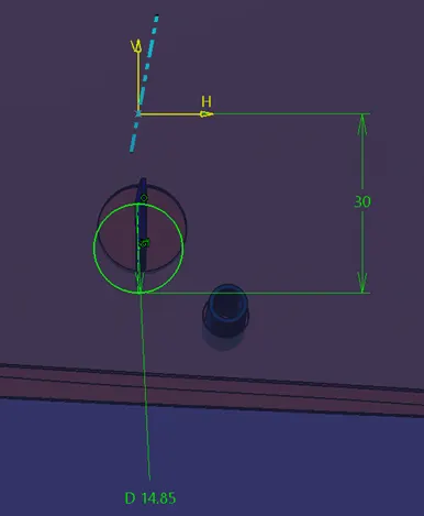
- Create the holes for the locaters to extrude above door attachment panel exactly at the center of the locater such that equal gap is maintained between locater walls and edge of the holes.
- 5-degree draft along the tooling direction should be given for the hole surface also.
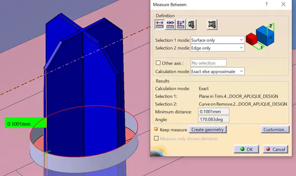
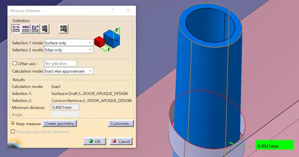
- The gap between the surface of the locater wall and the edge of the hole to be maintained with 0.1 mm each side
- Ensure the hole is created in tooling direction.
Four way locaters:
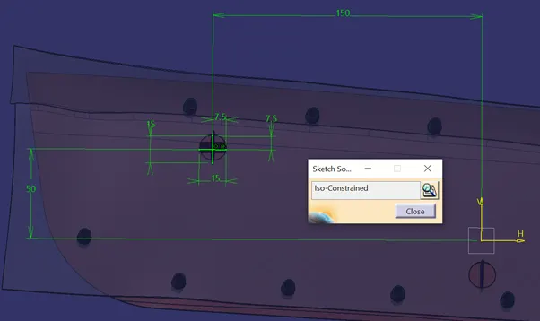
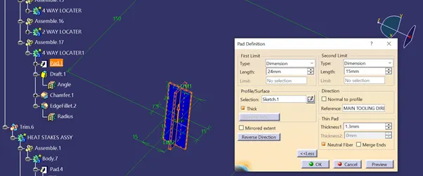
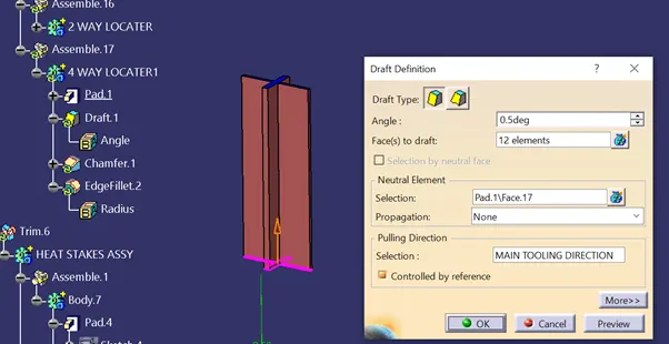
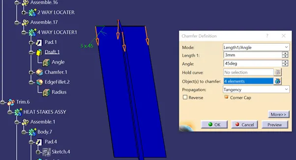
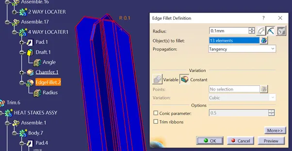
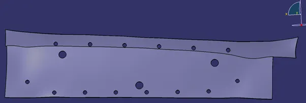
HOLES
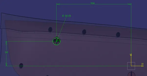
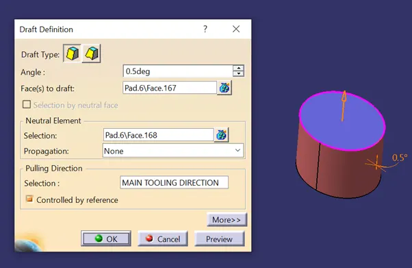
Two way locaters:
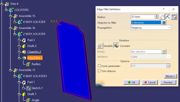
HOLES
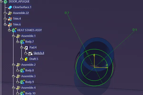
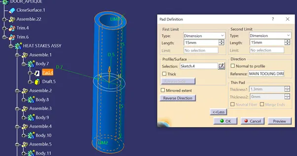
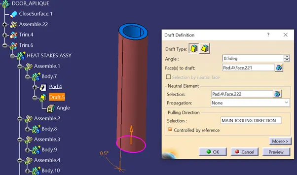
- HEAT STAKES:
Whenever two or more components need to be attached to one another, and at least one is made of a thermoplastic, a combination of heat and pressure can be used to reform the plastic to the many shapes or profiles to retain or join the parts together.
- Draft: 0.5 degree along main tooling direction
- Height maintained: at least 4 mm less than the height of locaters
- Thickness maintained: 2 mm
- Location: as per requirement
- Heat stakes should be extruded in the tooling direction always.
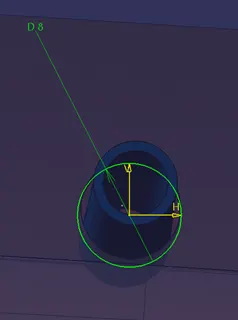
Openings for the locaters through door attachment panel
- Create the holes for the locaters to extrude above door attachment panel exactly at the center of the locater such that equal gap is maintained between locater walls and edge of the holes.
- 5-degree draft along the tooling direction should be given for the hole surface also.
- The gap between the surface of the locater wall and the edge of the hole to be maintained with 0.1 mm each side
- Ensure the hole is created in tooling direction.
HOLES
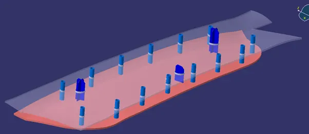
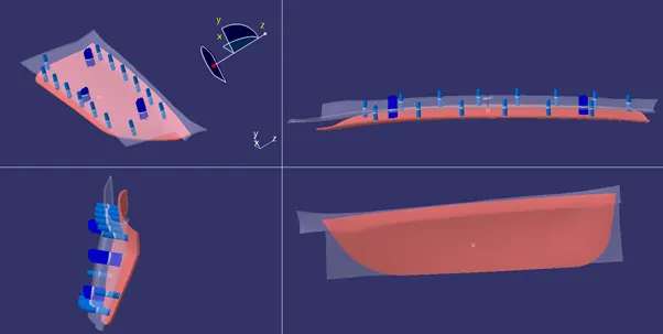
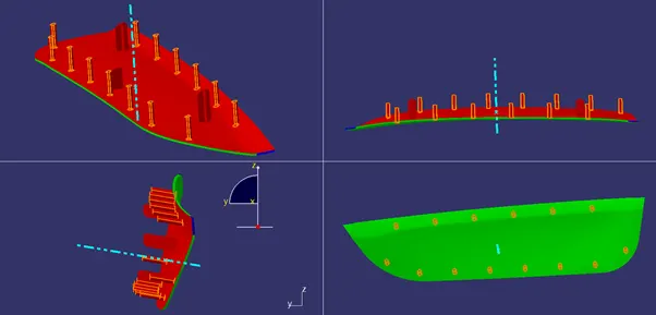
- DRAFT ANALYSIS ON FINAL SOLID COMPONENT:
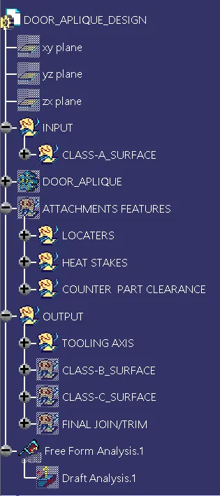
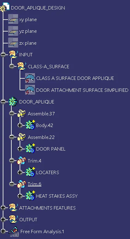
10.TREE STRUCTURE: