Week 8 - Challenge 2 - Base Bracket Design
REPORT
DRAFT ANALYSIS ON BASE BRACKET
TOOLING AXIS USING BISECTION METHOD
- Analyze the class-A carefully in all the direction(X,Y,Z) to decide the most feasible direction where the part can be cleared from the mould.
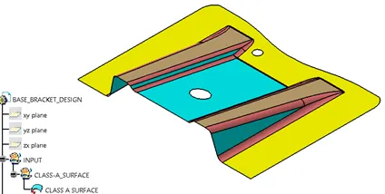
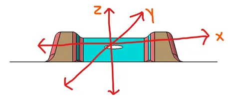
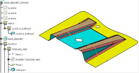
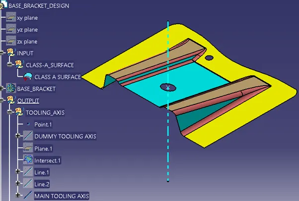
For example: class-A surface of BASE BRACKET image shown below indicating the 3 (X,Y,Z) direction
- If the tooling axis is provided in X-direction, then the two holes will be interfering during removal of the part from the mold.
- Similarly, if the tooling axis is provided in Y-direction again the holes will be interfering during part removal from the mold.
- But if the tooling axis is provided in Z-direction, then the part can be easily removed without any interference in the direction of holes.
- Hence let us assume z-direction as dummy tooling direction.
- Note: The axis line can be drawn on any area provided the direction is not violated.
- Bisection method
- Create a point and an axis system/plane at the center of the either hole using the point and YZ plane as reference.
- Using the YZ-plane create an intersection curve in X-direction as shown below.
- Create a bisection line using the intersection curve as shown in below image marked with a red arrow, which will be known as tooling clearing in x-direction.
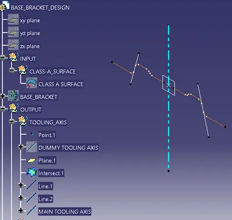
- So now we are having the tooling clearing x-direction
- In this case we will consider the tooling clearing x-direction as the main tooling direction.
- Because in y-direction we will not be able to get a profile to get a bisection line hence the tooling clearing x-direction will be our main tooling axis.
- So with the help of main tooling axis, we can now perform the draft analysis.
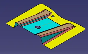
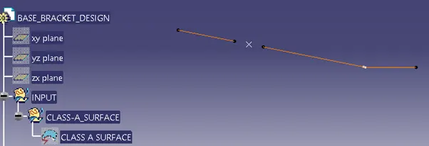
- Therefore we will not continue for bisection line in y-direction
- Below image showing the tooling clearing x-direction or final or main tooling direction
STEPS INVOLVED FOR PERFORMING DRAFT ANALYSIS ON BASE BRACKET
- Basic checks
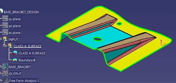
- Check the connectivity of the class-A surface i.e. ensuring there are no surface gaps between the surfaces.
- This can be done either visually or manually by creating boundary of the component.
- Disassemble the boundary which should result in three sub boundary curves only in this case, one as outer boundary ,larger hole and the smaller hole boundary.
- Draft analysis: enables you to detect if the part you drafted will be easily removed.
- The visualization mode should be set to Shading with Edges in the View > Render Style command before performing draft analysis.
- Go to insert<analysis<feature draft analysis

- The Draft Analysis dialog box is displayed. It gives information on the display (color scale), the draft direction and the direction values and identifying the maximum and minimum values for the analysis is displayed too.
- We will be using the default mode i.e. the quick mode as it simplifies the analysis in that .it displays only three color ranges.
- The maximum and minimum values for the analysis should be adjusted to 0 and 3 respectively as per the automotive industry as displayed below in the color range box.
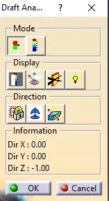
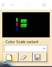
- Drag the compass by holding left mouse button on the red dot of the compass and place it on the main tooling axis randomly.
- Click the Compass icon
 to define the new current draft direction by aligning the compass exactly along the main tooling axis.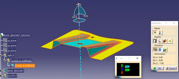
- Click the Locked direction icon
 , for locking the direction of the tooling axis.
 - After locking the direction single click on any random area on the component or surface.
- The part will be shown colored either or mixture of the three colors (green, red, blue) on it.
- Three bands of color on the part in the below example will indicate
- Green: the area has draft angle more than 3 degrees
- Blue: the area has the draft angle between 0 to 3 degrees.
- Red: the area has draft angle below 0 degrees (negative draft angle)
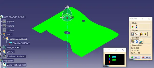
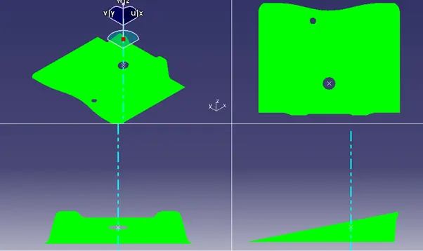
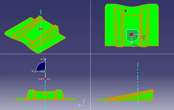
- In the above BASE BRACKET example the green area indicates that the part has draft angle more than 3 degrees and easily clearing the mold.
- Draft analysis performed on class-A surface after checking connectivity.
- Draft analysis performed on close surface or solid model after giving thickness of 2.5 mm.
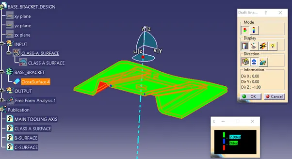
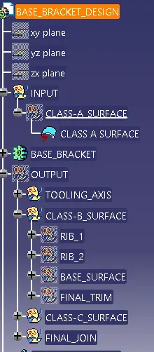
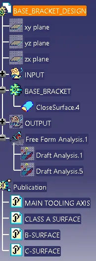
- Tree structure