Week 9 - PCB Thermal Simulation
Introduction of Challenge:
PCB (Printed Circuit Board), are used to mechanically support and electrically connect electronic components using conductive pathways, tracks or signal traces etched from copper sheets laminated onto a non-conductive substrate.
In our actual model, many passive components are placed over the printed circuit board along with heat sink. I have used required components only for analysis and followed all given instructions which are provided.
Case 1 (Conduction only)
Given Instruction,
1.consider a board without any components. Make all objects (including the openings) inactive except the BOARD_OUTLINE.1 object.
2.Select the cabinet and select Autoscale from the Edit window to make the size of the board and the cabinet the same.
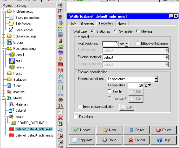
3.Min z: Temperature from the External conditions drop-down list, and keep the ambient temperature (20°C).
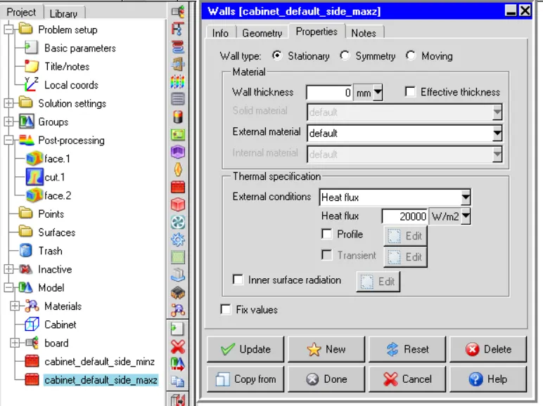
4.Max z: specify a Heat flux of 20000 W/m2 in the Thermal specification
5.The rest of the sides are insulated. The board will be simulated using a conduction-only model.
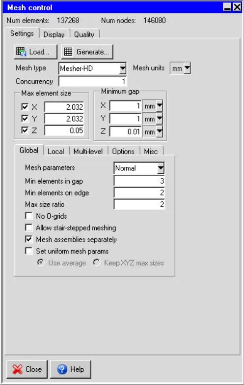
6.Generate mesh. Specify a Max element size for X, Y, and Z as 2.032, 2.032, and 0.05 mm respectively, and a Minimum gap for X, Y, and Z as 1, 1, and 0.01 mm respectively.
Geometry
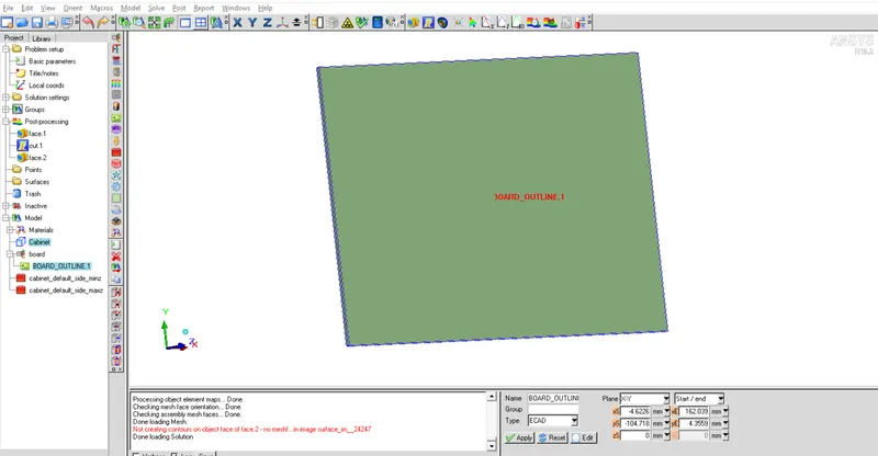
As per instruction, i have kept only PCB and deactivated all components. Then, used Cabinet as Wall.
PCB,
Wall (Minz)
Wall(MaxZ)
Mesh
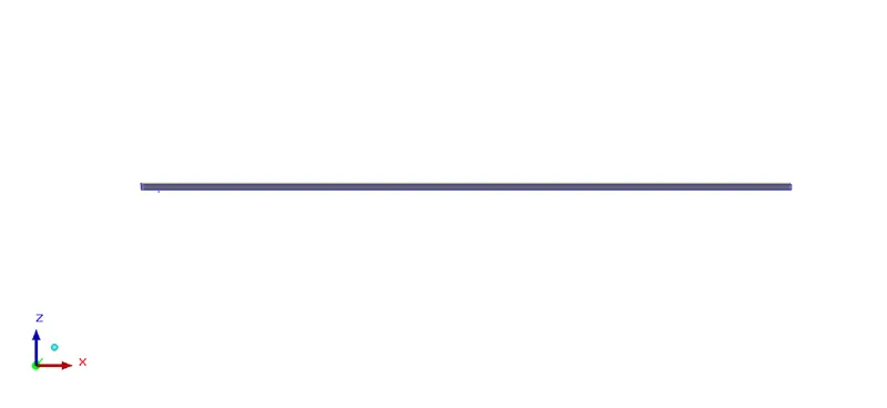
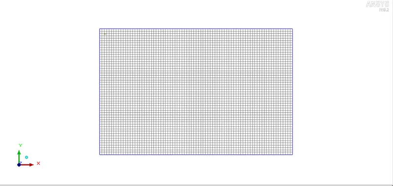
Done meshing with given instruction and shown here Visual and Quality inspection results.
Quality Inspection,
Face Alignment : 1.0
Volume : 1.64139e-10
Skewness : 1.0
Mesh Control,
X-Axis cut plane

Y-Axis cut plane
Z-Axis cut plane
Solver Setting
Basic Parameters
Variable Solved : Temperature
Radiation : OFF
Flow regime : Laminar
Natural convection : Gravity Vector- OFF
Used Default material values
Used Steady state analysisSolution Initialization
X velocity : -1 m/s
Boussinesq eqaution : Operating pressure - 101325N/m2
Basic Setting
Number of iteration : 500
Convergence Criteria : Flow(1e-3), Energy(1e-12), Joule heating (1e-7)
Parallel Setting
Parallel processor : 4
GPU used : 1
Specify monitor point output frequency : 10
Enabled autosave interval
Advanced Setting
Discretization scheme
Pressure- First
Momentum - First
Temperature - First
Under relaxation
Pressure- 0.3
Momentum - 0.7
Temperature - 1.0
Viscosity - 1.0
Body forces - 1.0
Linear Solver
Pressure - Type(V), Termination criterion(0.1), Residual reduction tolerance(0.1), Stabilization(None)
Momentum - Type(flex), Termination criterion(0.1), Residual reduction tolerance(0.1)
Temperature - Type(F), Termination criterion(1e-6), Residual reduction tolerance(1e-6), Stabilization(None)
Joule heating - Type(F), Termination criterion(1e-6), Residual reduction tolerance(0.7), Stabilization(None)
Used double precision
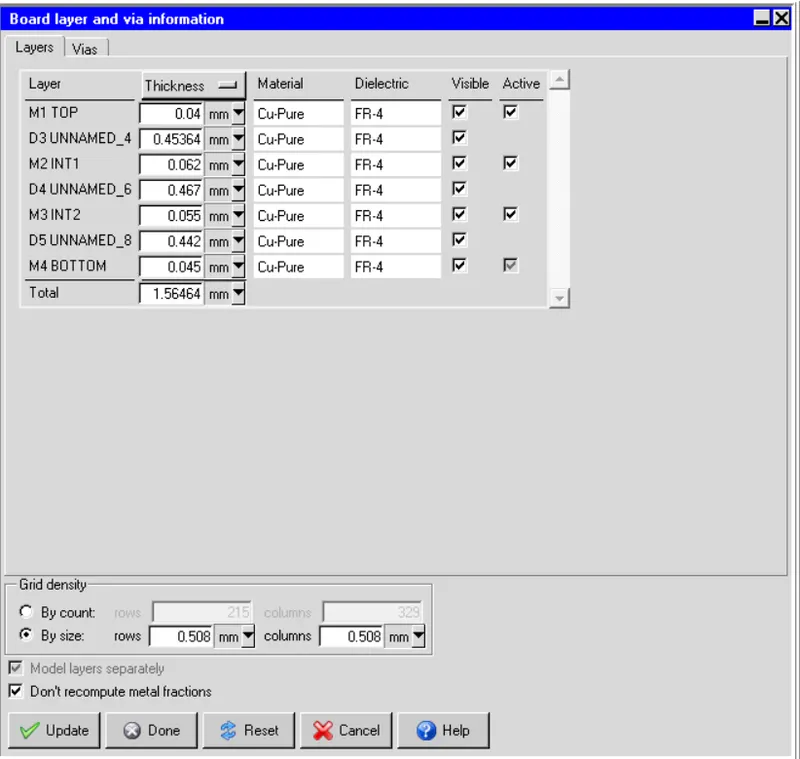
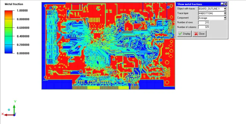
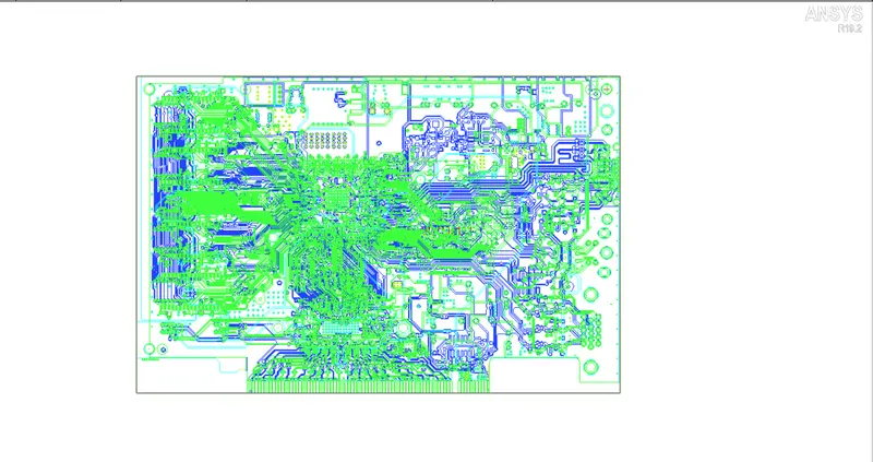
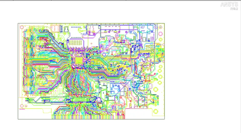
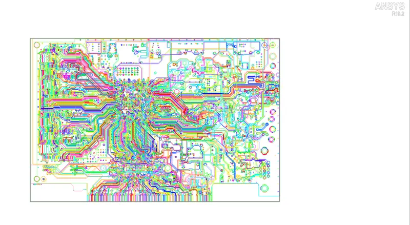
Layer Information and metal fraction Grid setting
Metal fraction (Bottom)
Trace Visibility (Colour by Layer)
Trace Visibility (Colour by traces)
Trace Visibility (Colour by Net)
Post processing
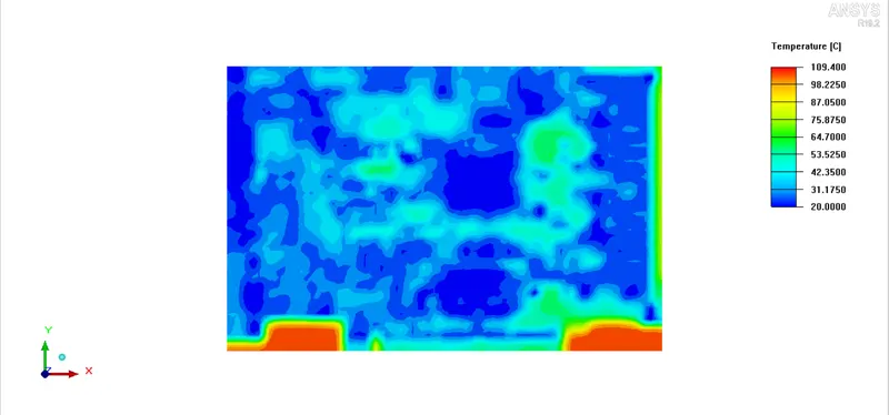
Min temp is 20 degree, max temp is 109.4 degree( Max temperature was raised at less metal area)
Contour Temperature
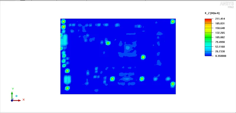
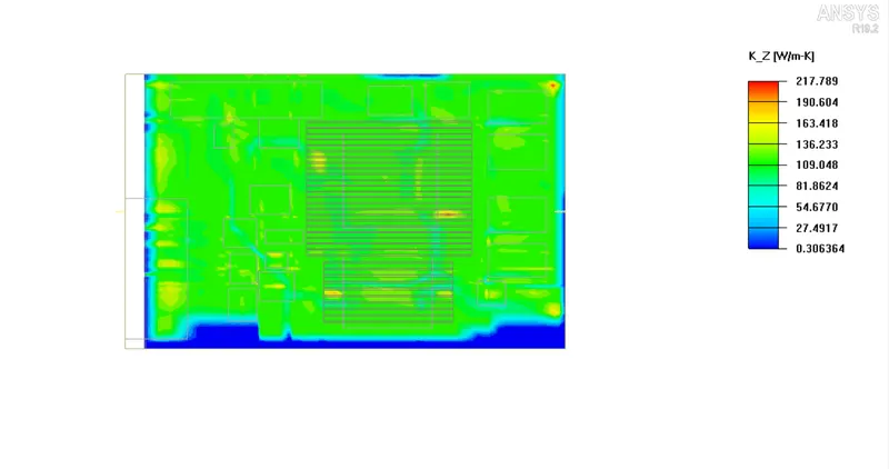
Plane cut contour(K_Z)
Case 2 (Force Convection)
Given Instruction,
1.put the actual components back into the model
2.Highlight the two wall objects created for the “conduction only" model and drag them into the Inactive folder. Click on the Cabinet and Autoscale it from the Edit window.
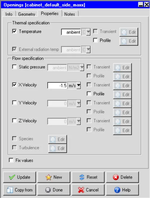
3.assign an X Velocity of -1.5 m/s for Max x side of the cabinet
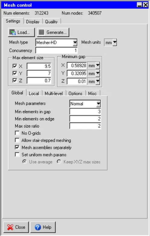
4.Generate mesh. Specify a Max element size for X, Y, Z as 9.5, 7, and 0.7 mm respectively.
Convection heat transfer is complicated since it involves fluid motion as well as heat conduction. The fluid motion enhances heat transfer (the higher the velocity the higher the heat transfer rate).
Geometry
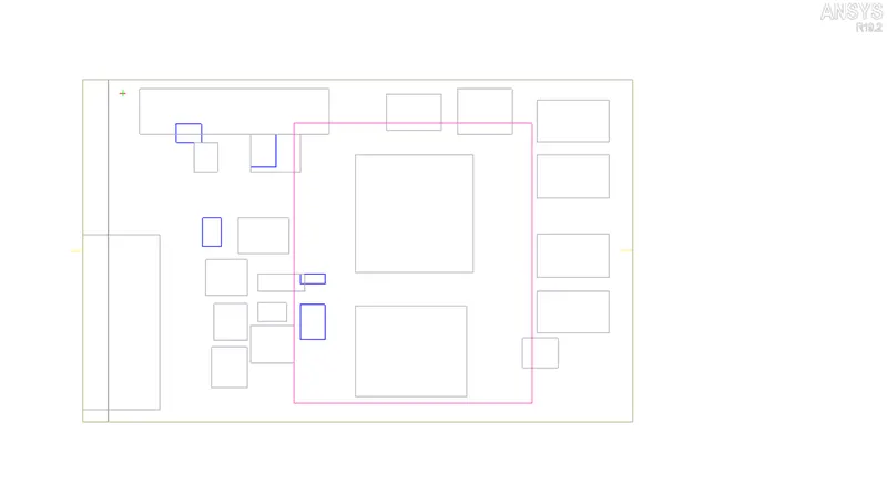
I have brought up all inactive components to active and used Max X velocity as -1.5m/s.
MaxX
Mesh
i have set provided values and done meshing. Shown here Visual and Quality Inspection results.
Quality Inspection,
Face Alignment : 1.0
Volume : 8.1161e-13
Skewness : 1.0
X-Axis cut plane
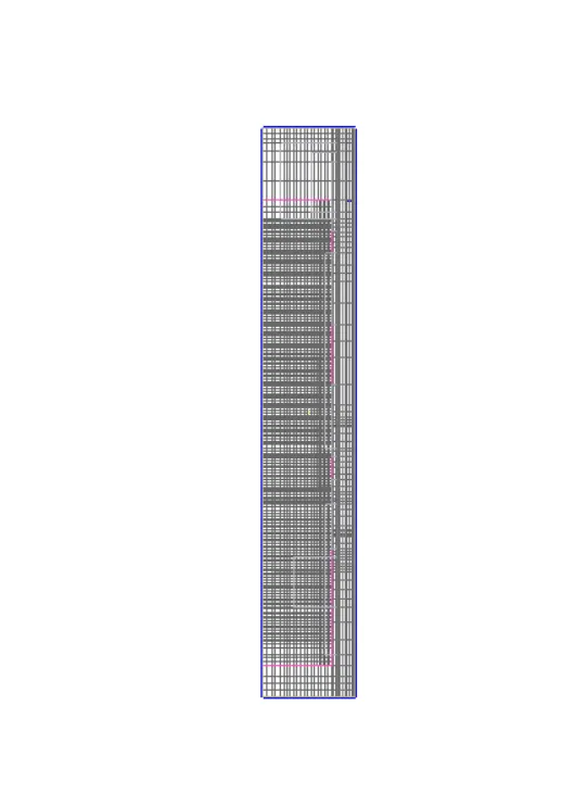
Y-Axis cut plane
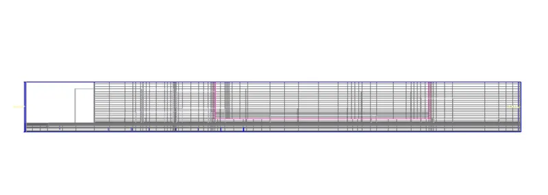
Z-Axis cut plane
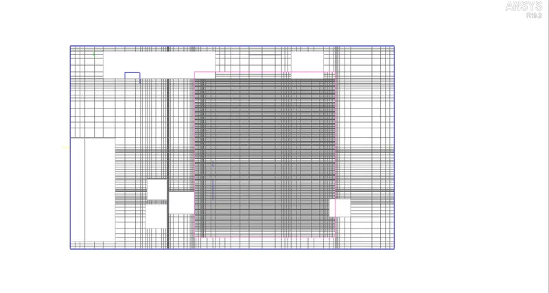
Solver Setting
Basic Parameters
Variable Solved : Flow,Temperature
Radiation : OFF
Flow regime : Turbulent
Natural convection : Gravity Vector- OFF
Used Default material values
Used Steady state analysisSolution Initialization
X velocity : -1 m/s
Boussinesq eqaution : Operating pressure - 101325N/m2
Basic Setting
Number of iteration : 500
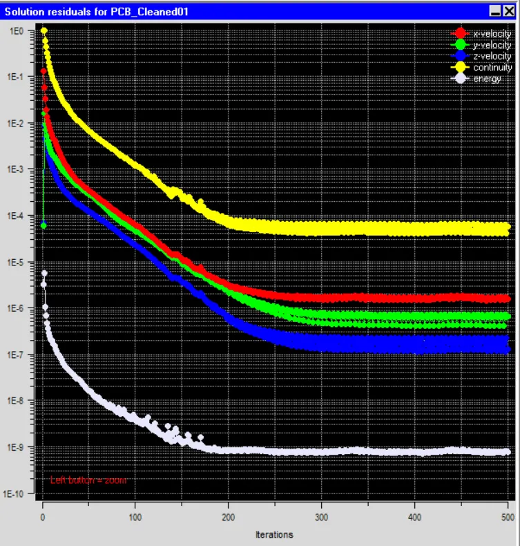
Convergence Criteria : Flow(1e-5), Energy(1e-12), Joule heating (1e-7)
Parallel Setting
Parallel processor : 4
GPU used : 1
Specify monitor point output frequency : 10
Enabled autosave interval
Advanced Setting
Discretization scheme
Pressure- First
Momentum - First
Temperature - First
Under relaxation
Pressure- 0.3
Momentum - 0.7
Temperature - 1.0
Viscosity - 1.0
Body forces - 1.0
Linear Solver
Pressure - Type(V), Termination criterion(0.1), Residual reduction tolerance(0.1), Stabilization(None)
Momentum - Type(flex), Termination criterion(0.1), Residual reduction tolerance(0.1)
Temperature - Type(F), Termination criterion(1e-6), Residual reduction tolerance(1e-6), Stabilization(None)
Joule heating - Type(F), Termination criterion(1e-6), Residual reduction tolerance(0.1), Stabilization(None)
Used double precision
Residual Plot
Post processing
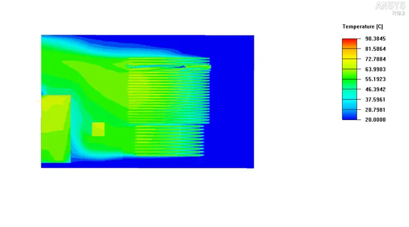
Contour Temperature
Plane cut contour(K_Z)
Case 3 (Joule Heating)
Given Instruction,
a, Build the Model – Edit the Board outline of the previous model to open the model trace heating panel select INT1_3 layer -> filter the trace to view by setting Min Area in the Display traces
filter group box use a Min Area of 4124 mm2.
b, Before you create a solid trace of trace A3V3_2261 set the Max angle filter to 135 and the Min length filter to 1.0 m to ignore the fine details in the trace geometry and reduce the mesh count.
c, Create a solid polygonal solid block for trace A3V3_2261
d, Select the polygonal trace just created from the Model manager window Under Thermal specification next to Joule heating, click Edit to open the Joule heating power panel. Set
Resistivity, temperature coefficient (C), and reference temperature (Tref).
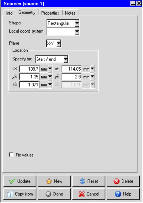
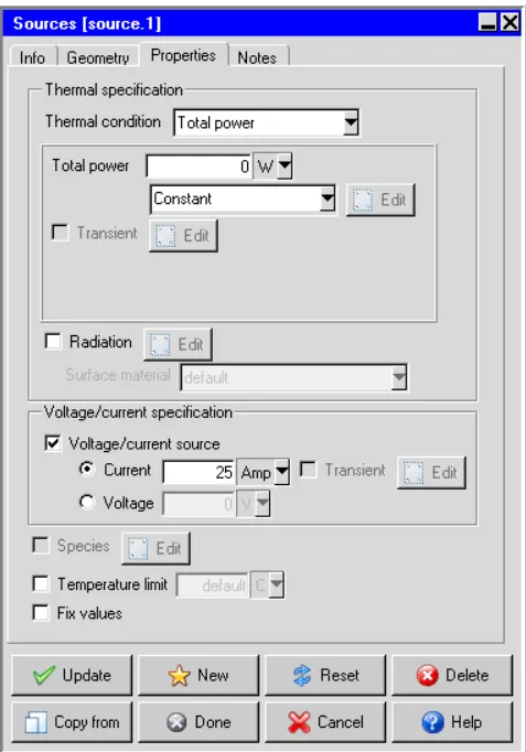
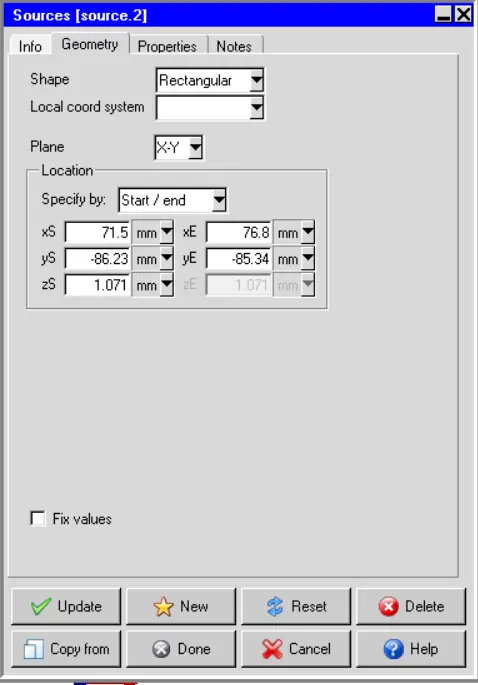
e, One source is for the current source (source.1) and the other for the voltage source (source.2). Both sources are created at the same layer as the layer of the wire in. The area of each source is the area to apply the voltage or the current. The recommendation of the source objects pair for joule heating is the current-voltage pair or voltage- voltage pair
Geometry
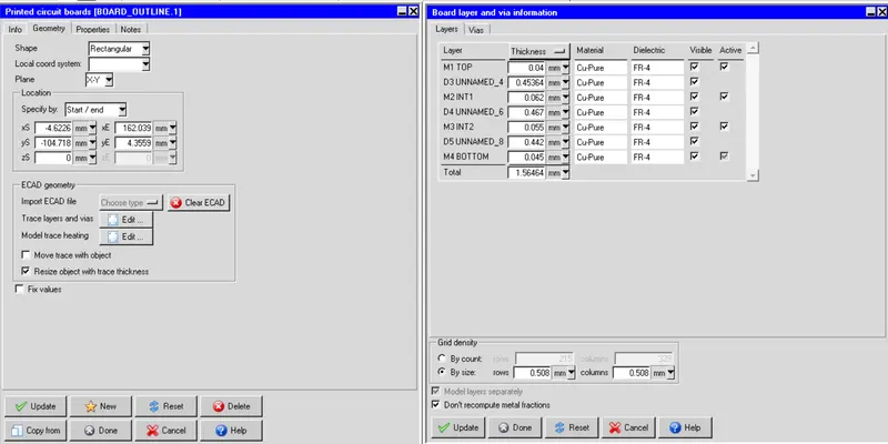
As per the instruction, i have created Solid trace for A3V3_2502 and placed two source in edge of boundary.
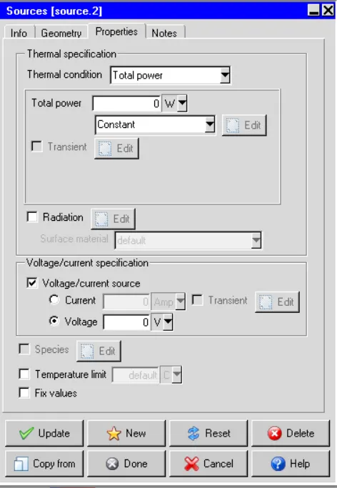
Considered source as Voltage-current pair and setting shown here below,
Solid Trace
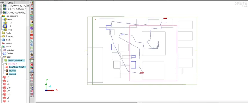
Board property and layer information
Source1
Source1(Current)
Source2
Source2(Voltage)
Mesh :
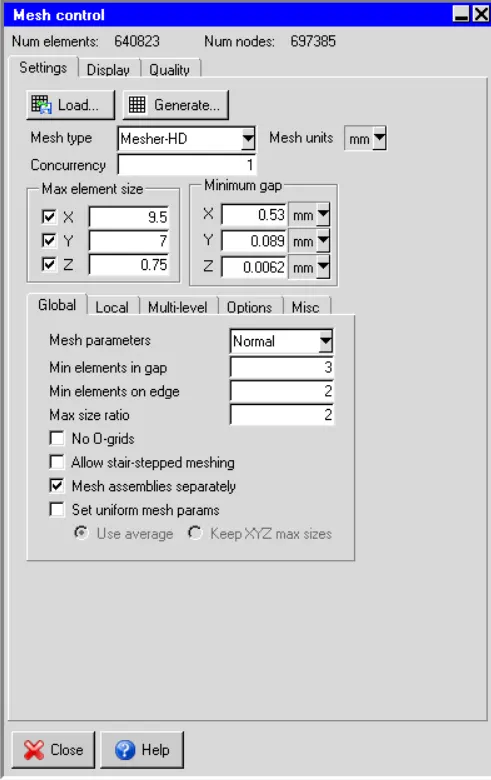
Created assembly for solid trace and sources, done meshing with given values.
Quality Inspection,
Face Alignment : 0.0769057
Volume : 1.11034e-13
Skewness : 4.72807e-06
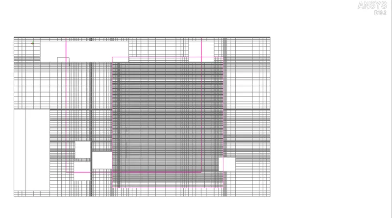
Mesh Control
X-Axis cut plane
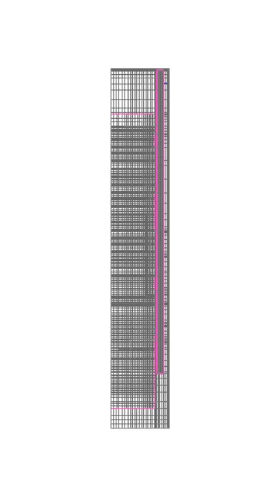
Y-Axis cut plane
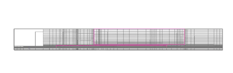
Z-Axis cut plane
Solver Setting
Basic Parameters
Variable Solved : Flow,Temperature
Radiation : OFF
Flow regime : Turbulent
Natural convection : Gravity Vector- OFF
Used Default material values
Used Steady state analysisSolution Initialization
X velocity : -1 m/s
Boussinesq eqaution : Operating pressure - 101325N/m2
Basic Setting
Number of iteration : 500
Convergence Criteria : Flow(1e-4), Energy(1e-8), Joule heating (1e-7)
Parallel Setting
Parallel processor : 4
GPU used : 1
Specify moitor point output frequency : 10
Enabled autosave interval
Advanced Setting
Discretization scheme
Pressure- First
Momentum - First
Temperature - First
Under relaxation
Pressure- 0.3
Momentum - 0.7
Temperature - 1.0
Viscosity - 1.0
Body forces - 1.0
Linear Solver
Pressure - Type(V), Termination criterion(0.1), Residual reduction tolerance(0.1), Stabilization(None)
Momentum - Type(flex), Termination criterion(0.1), Residual reduction tolerance(0.1)
Temperature - Type(F), Termination criterion(1e-6), Residual reduction tolerance(1e-6), Stabilization(BCGSTAB)
Joule heating - Type(W), Termination criterion(1e-6), Residual reduction tolerance(0.1), Stabilization(BCGSTAB)
Used double precision
Post Processing
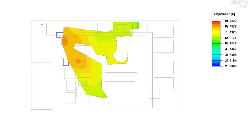
Max temperature was 91.3233 degree.
Contour temperature