Week 6.1 - Setting up a model (Electronic enclosure)
Aim : To simply given CAD geometry of electronic enclosure and create model in icepak to perform thermal analysis.
Geometry :
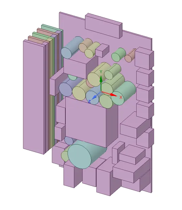
Used Week 3 simplified model to proceed meshing. Before reuse it, checked everything has been done correctly or not.Removed small bodies which are not recommended to analysis.Ensured all bodies has been simplified with required level.
Bottom Enclosure,
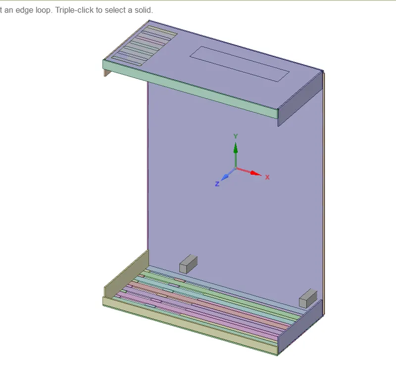
Top Enclosure,
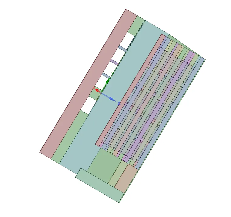
Model,
Meshing :
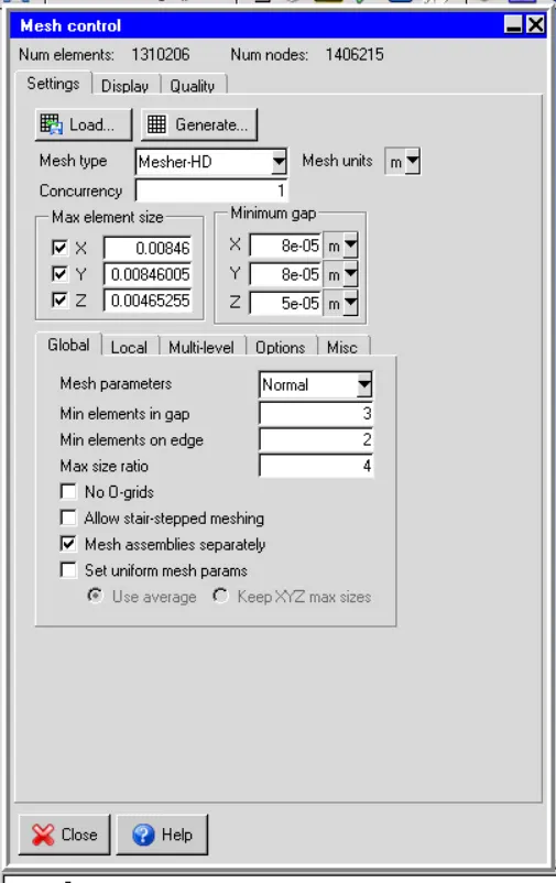
I have done few adjustment on icepak primitive shapes to make fine meshing. Used assembly concept to proceed meshing. Each assembly contain list of bodies which are closest to each others. Set slack setting and used global mesh values. Before proceed meshing, done Automatic validation checking and ensured the model has no issues with them.
Mesh Control :
Cut plane through the X-axis:
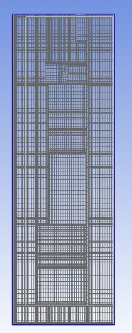
Cut plane through the Y-axis:
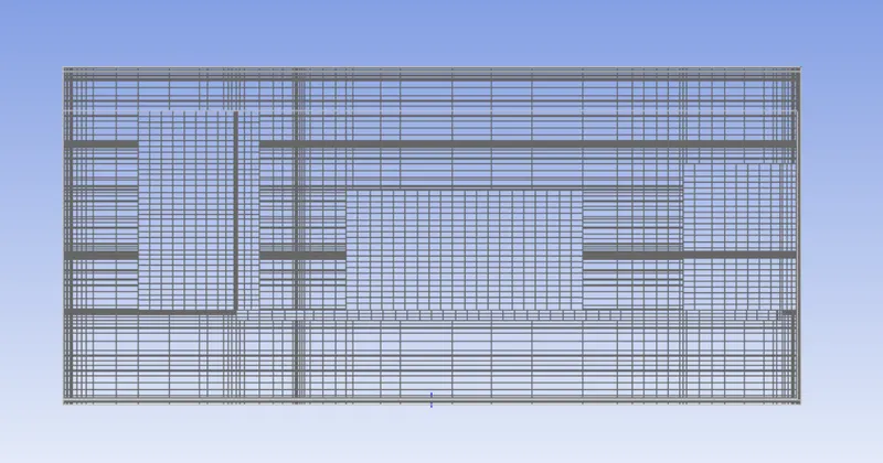
Cut plane through the Z-axis:
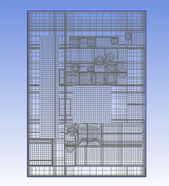
Solver Setting:
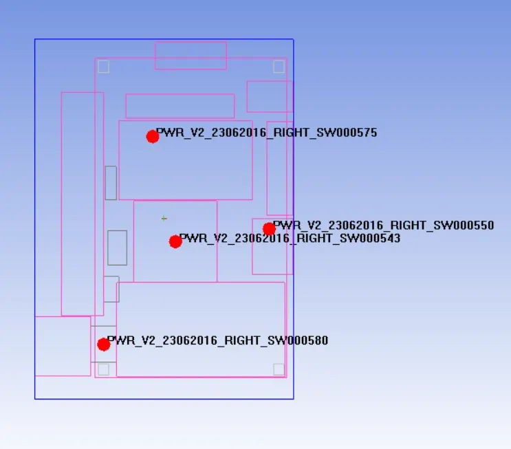
Assumed below components are active sources which will be generate heat and done setting for steady state analysis.
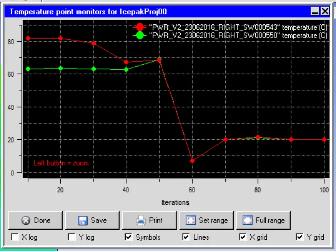
- PWR_V2_23062016_RIGHT_SW000543 - 10W
- PWR_V2_23062016_RIGHT_SW000550 - 2W
- PWR_V2_23062016_RIGHT_SW000580 - 2W
- PWR_V2_23062016_RIGHT_SW000575 - 5W
Marker points,
Numerical Setting:
* Enabled flow and temperature variables
* Turbulant flow used with natural convection gravity vector -9.80685 m/s2
* Steady state analysis with boussinesq natural convection
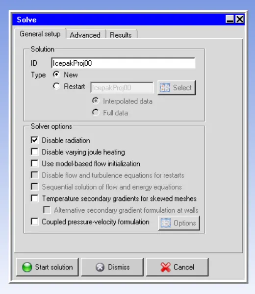
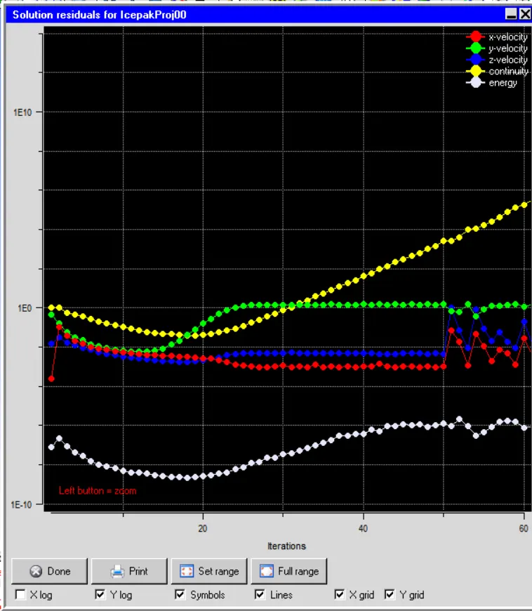
* Used no of iteration is 100 and convergence criteria for flow 0.0001, energy 1e7, and joule heating 1e-7
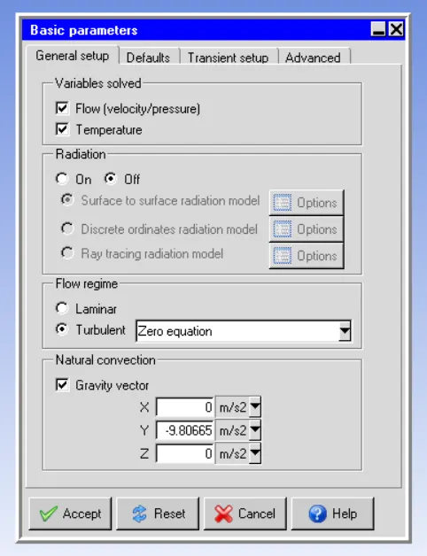
Transient setup,
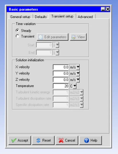
Advanced basic Setting,
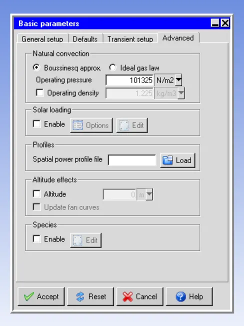
Advance and Basic settings are used as it,
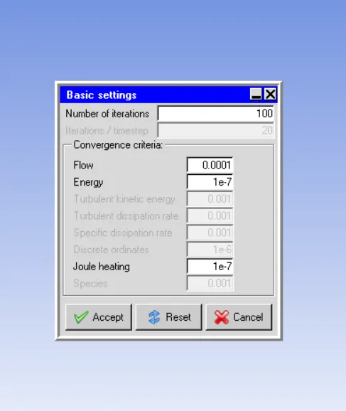
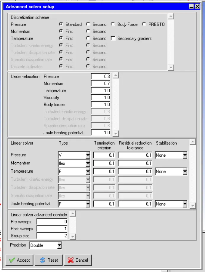
Advanced Setting,
Solver Setting,
Residual plot:
Temperature Plot,
Contour Plot by Z axis plane cut,
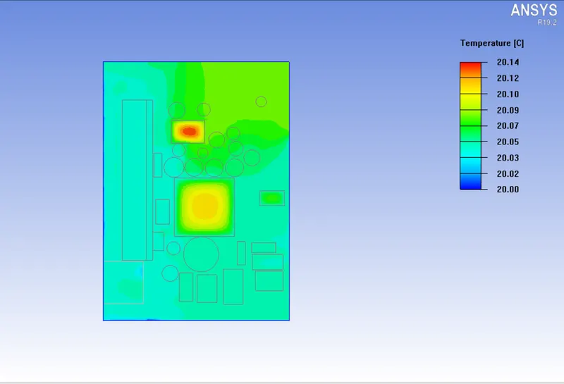
Entire component temperature,
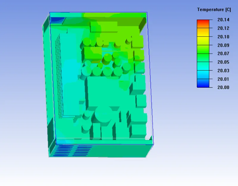
Conclusion :
We have done successfully thermal analysis for electronic enclosure and shown contour plots by post processing.