Week 9 - Parametric study on Gate valve.
Aim :
1) To perform a parametric study on gate valve simulation by varying the valve opening measurements .
2) Obtain mass flow rates at outlet for each design points .
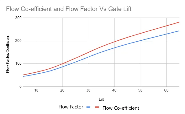
3) Calculate flow co-efficient and flow factor for each opening and plot the graph .
4) Discuss results for mass flow rate and flow co-efficient .
Theory:
A gate valve controls the media's flow by lifting the gate (open) and lowering the gate (closed). A gate valve's distinct feature is the straight-through unobstructed passageway, which induces minimal pressure loss over the valve. The unobstructed bore of a gate valve also allows for a pig's passage in cleaning pipe procedures, unlike butterfly valves. Gate valves are available in many options, including various sizes, materials, temperature and pressure ratings, and gate and bonnet designs.
Gate valves tend to be slightly cheaper than ball valves of the same size and quality. They are slower in actuation than quarter-turn valves and are for applications where valve operation is infrequent, such as isolating valves. Gate valves should be used either fully open or fully closed, not to regulate flow. Automated gate valves exist with either an electric or pneumatic actuator, but a manual gate valve is cost-effective since they have infrequent usage.
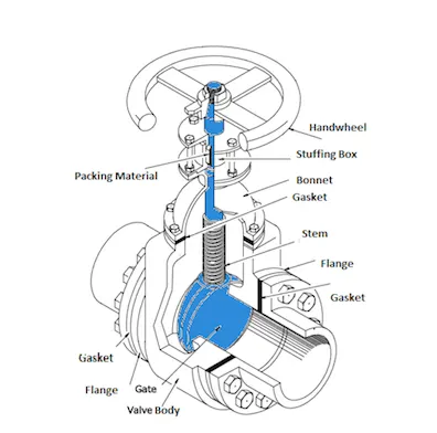
A gate valve's main components are body, seat, gate, stem, bonnet, and actuator (above figure). The primary operation mechanism is straightforward. Turning the handwheel rotates the stem, which moves the gate up or down via the threads. They require more than one 360° turn to fully open/close the valve. Lifting the gate from the path of the flow, the valve opens. Lowering the gate to its closed position seals the bore resulting in a full closure of the valve.
For a gate valve, the relationship between the gate's vertical travel and the flow rate is nonlinear, with the highest changes occurring near shutoff. When used to regulate flow, the relatively high velocity of the flow at partial opening results in gate and seat wear, which along with possible vibrations of the gate, shortens the valve's service life.
Geometry :
The model STEP file was imported to space claim .
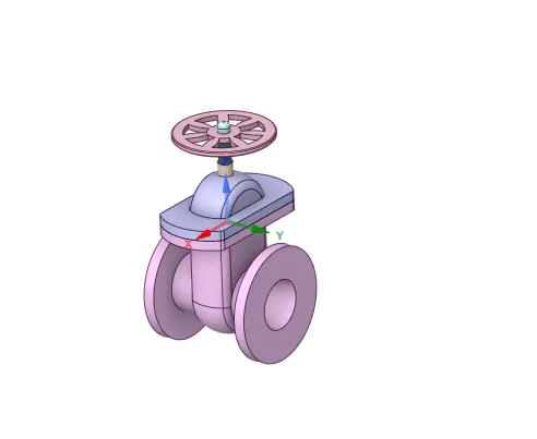
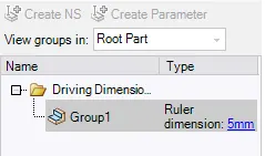
Move option from design tab was used to move the gate component and parametrize it .
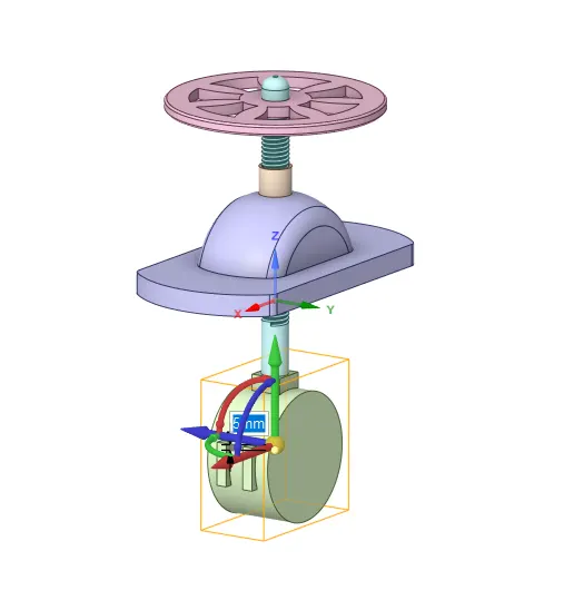
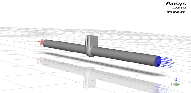
Required volume was extracted using extract volume option . The inlet and oulet face of the valve was extended to a length o 800mm each using pull tool .
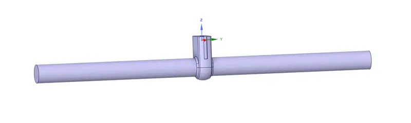
The extracted volume was updated by using update volume body by context option and rest of the model was supressed for physics.
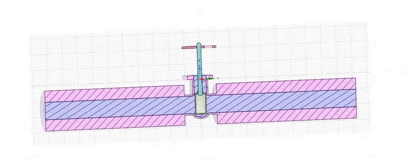
Thus geometry clean up was completed and model was imported for meshing.
Mesh :
The model was meshed according to default mesh parameters .
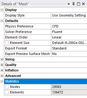
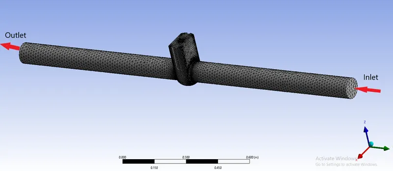
Named selections were given to inlet and otlet face of the valve .
Thus meshing was completed an SETUP module was opened .
SETUP:
The set up was opened with double precision and 4 processors for solving .
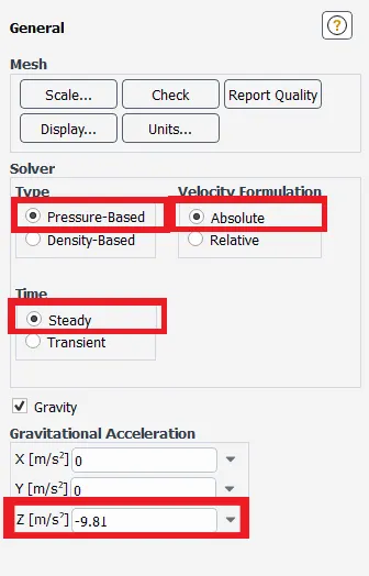
The general solver setting was made to pressure based steady state solver with absolute velocity formulation and Gravity was intorduced with a value of 9.81m/s in -Z direction .
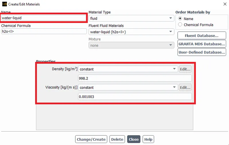
Water (liquid) was selected from fluent database and was set as the working fluid .
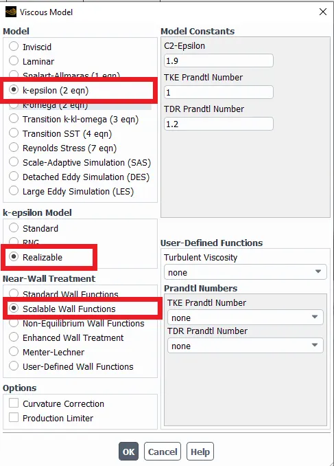
The Viscous model was set to k-epsilon with realizable and scalable wall functions
Boundary condition :
Inlet was set as pressure inlet and value of 10Pa was given at inlet . All other boundary conditions were automatically assigned by the solver .
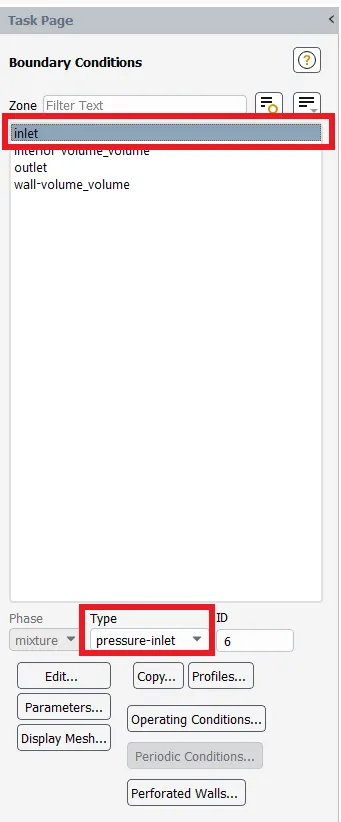
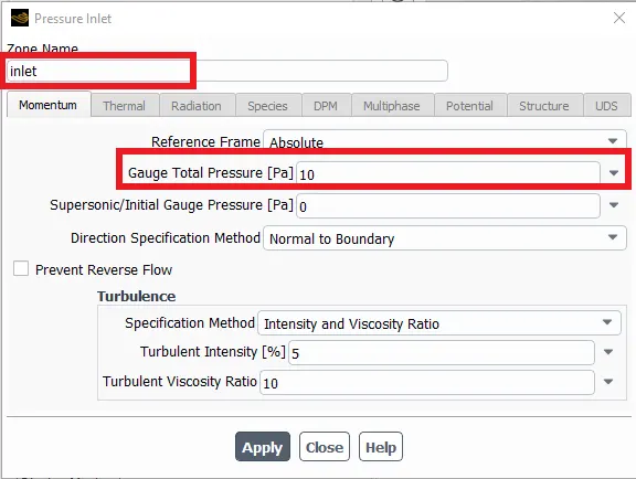
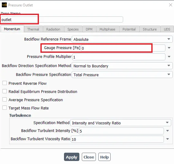
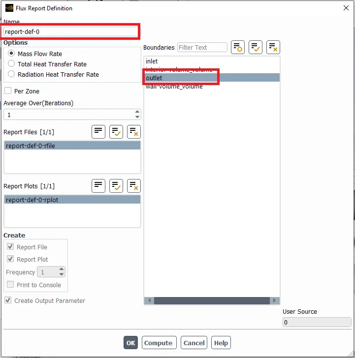
Report Definitions were made for mass flow at outlet .
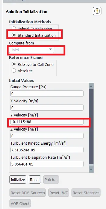
The simulation was initialized using stanard option with reference from inlet.
Contours were created along xy plane for pressure and velocity .
Solution animation was created for velocity contour.
Simulation was run for 250 iterations .
Results:
Case 1 :
Valve lift : 5mm
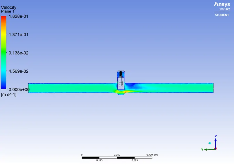
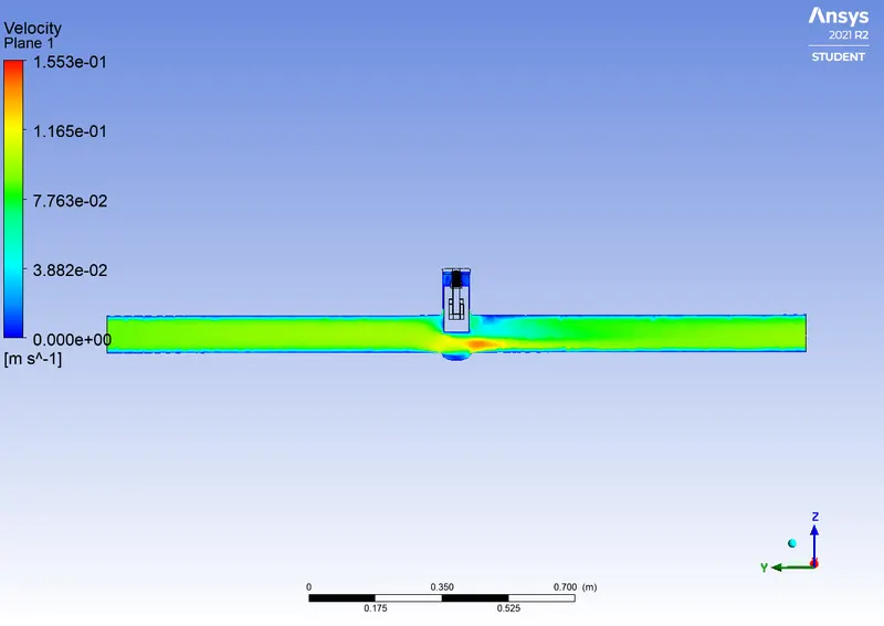
Velocity Contour

Case 2 :
Valve lift : 15mm
Velocity Contour
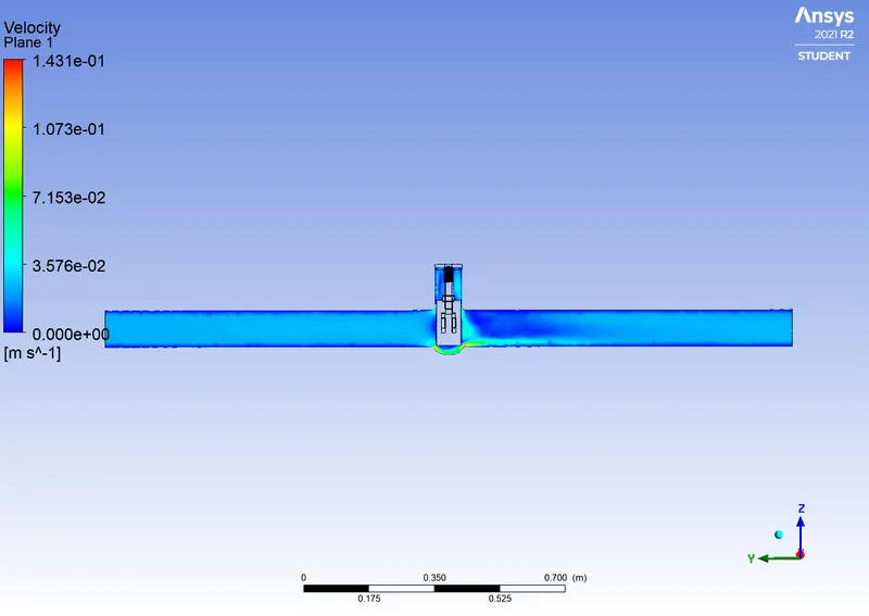
Case 3 :
Valve lift : 25mm
Velocity Contour
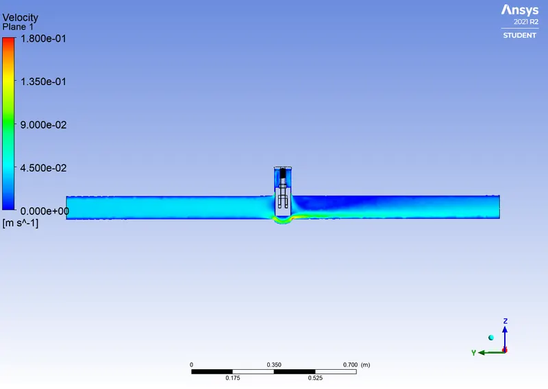
Case 4 :
Valve lift : 35mm
Velocity Contour
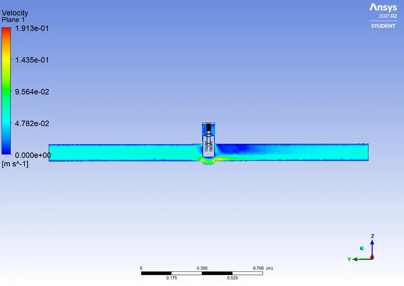
Case 5 :
Valve lift : 45mm
Velocity Contour
Case 6 :
Valve lift : 65mm
Velocity Contour
Parametrized Report Definition for mass flow rate at outlet
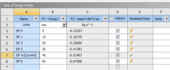
Table for values of Flow rate and Flow co-efficient of various cases
| Case No: |
Mass flow rate in kg/s |
Mass flow rate in m^3/hr |
Flow factor `k_v` |
Flow co-eficient `C_v` |
| 1 | 0.12307 | 0.44305 | 44.305 | 51.219 |
| 2 | 0.18735 | 0.67446 | 67.446 | 77.972 |
| 3 | 0.29689 | 1.0688 | 106.88 | 123.506 |
| 4 | 0.41782 | 1.50415 | 150.415 | 173.891 |
| 5 | 0.51407 | 1.85605 | 185.605 | 214.572 |
| 6 | 0.67588 | 2.43317 | 243.317 | 281.291 |
Inference :
1) Higher the valve lift , greater the mass flow rate .
2)The mass flow rate is directly proportional to flow factor and flow co-efficient .