Week 9 - Parametric study on Gate valve.
CHALLENGE FOR GATE VALVE SIMULATION:
Objective:
For this challenge, you will have to perform a parametric study on the gate valve simulation by setting the opening from 10 % to 80%.
- Obtain the mass flow rates at the outlet for each design point.
- Calculate the flow coefficient and flow factor for each opening and plot the graph.
- Discuss the results of the mass flow rate and flow coefficient.
Answer:
Modeling in Spaceclaim:
Given 3D model:
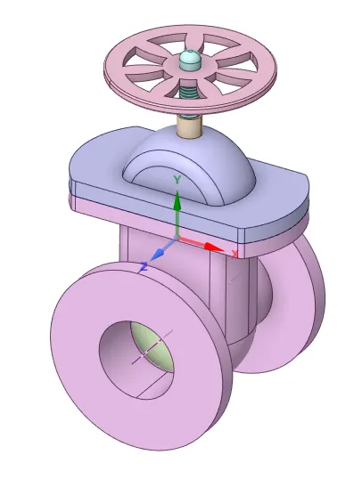
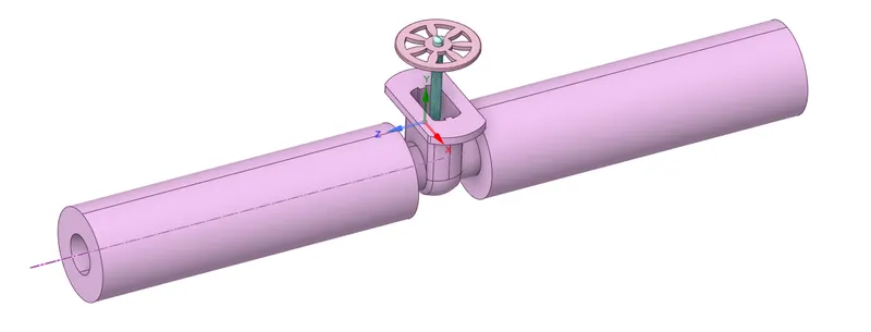
3D model inlet & exhaust has been extended to accommodate fluid volume necessary to simulate gate valve.
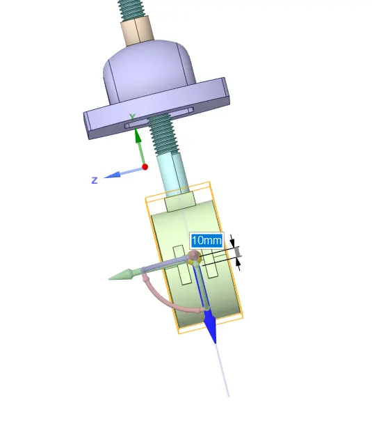
The valve has been opened 10mm to calculate mass flow rate of water.
The fluid volume extracted using Volume extract option by selecting boundaries to make it closed volume.
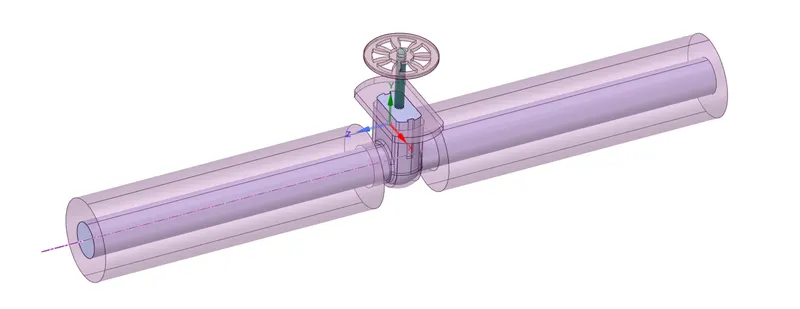
Final fluid volume
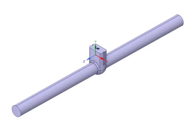
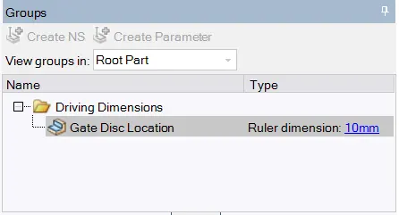
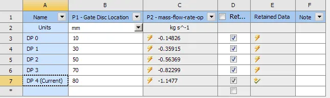
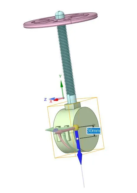
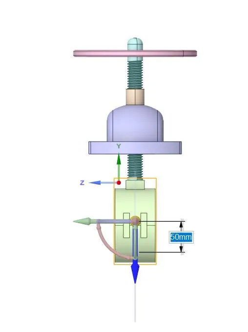
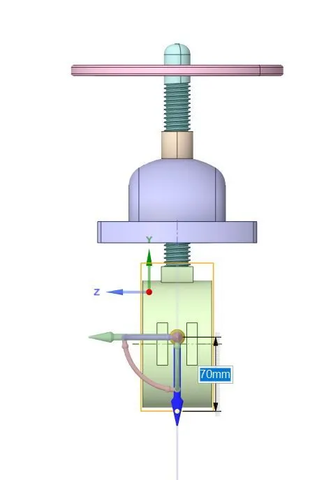
The simulation has been carried out number of valve opening from 10mm to 80mm. The dimension of valve opening has been parameterize to simplify simulation process of similar type with different valve opening. The parameter has been created for valve opening by creating group shown in the below image.
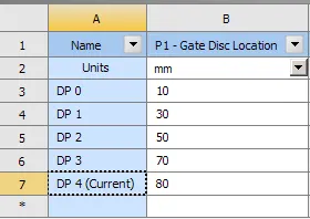
Based on created parameter in the group section, number of design points has been assigned to carry out the simulations. The gate valve simulations will be carried out for 10mm, 30mm, 50mm, 70mm & 80mm valve opening to measure the mass flow rate at the outlet.
Meshing:
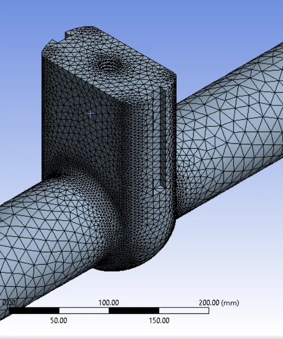
The meshing has been performed on the extracted fluid volume. The element size is considered as 70mm. The number of element generated during mesing process is 134294.
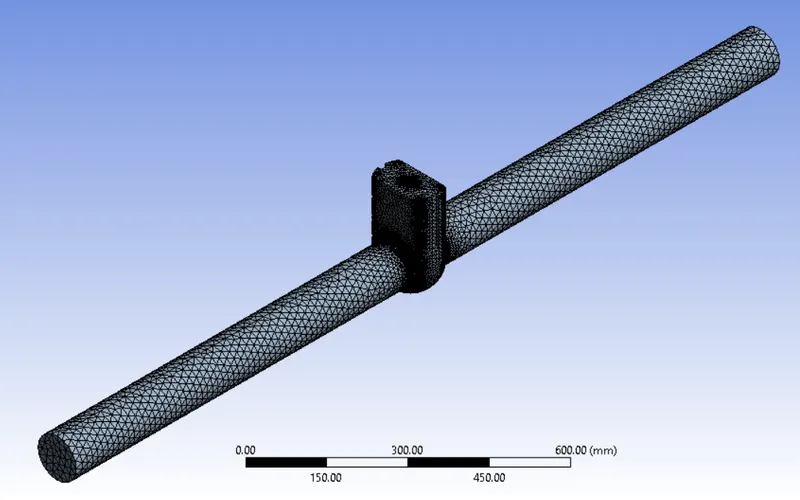
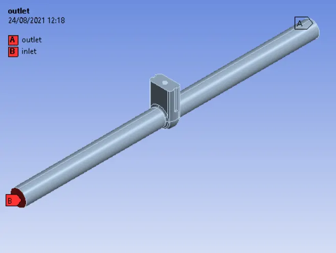
Inlet & outlet of the fluid volume is assigned the name using named selection option.
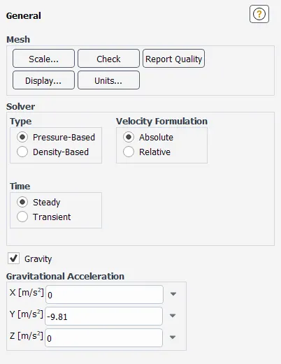
Simulation Setup:
General conditions of simualtion. Gravity has been considered in the -Y direction.
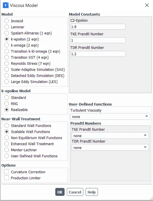
k-epsilon (2-eqn) with Realizable viscous model has been considered scalable near-wall treatment condition.
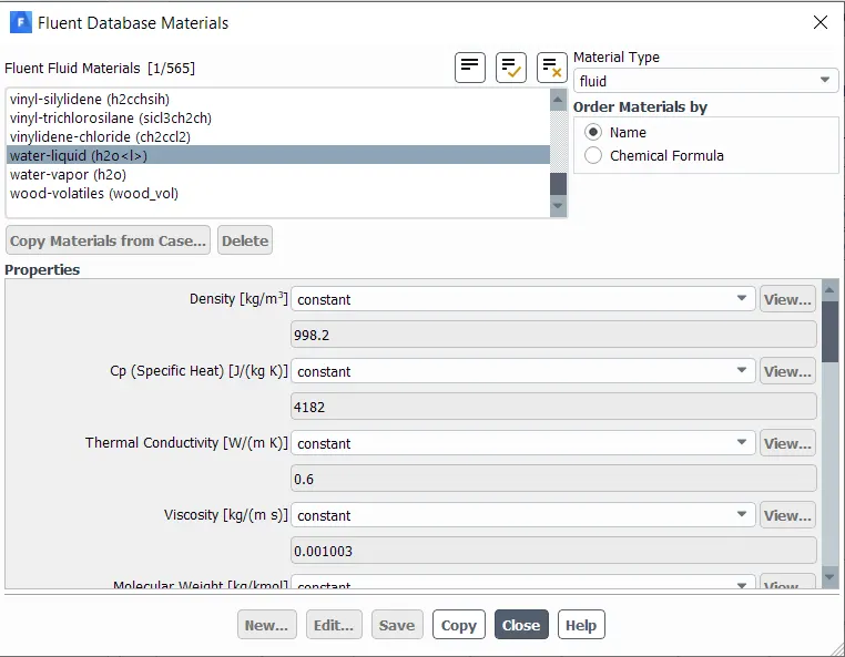
Water - liquid material is assigned for the fluid flowing in the valve. From material database available in the Create material option, the water fluid has been considered with default properties. The same material has been assigned to fluid volume.
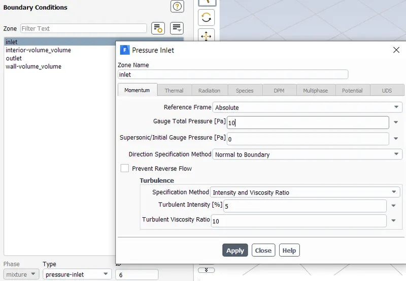
Inlet boundary condition is assigned from the Boundaries options available in Physics tab of Ansys fluent. The boundary is considered as pressure-inlet type & 10Pa gauge total pressure is inserted in the inlet condition dialogue box.
Solution:
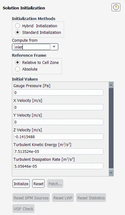
Standard initialization is performed before solving the physics of the model.
After initializating the solution process, the output parameters & reauired contour images & animation file has been activated for post processing.
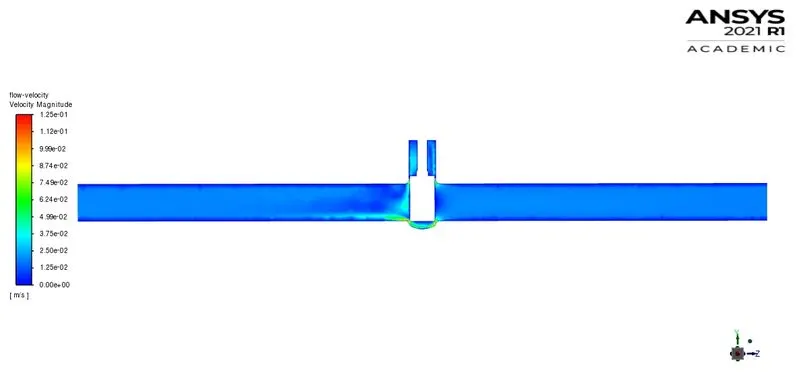
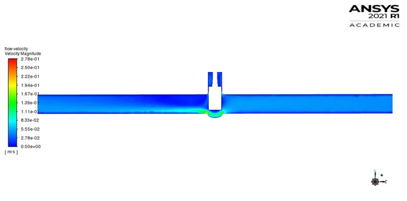
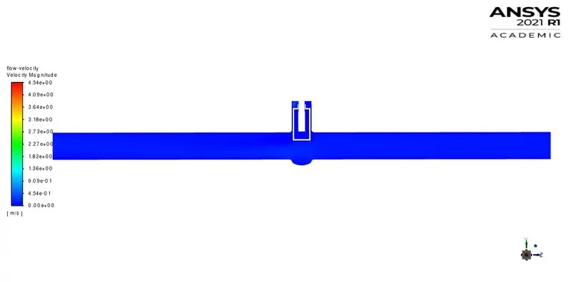
First of all, flow velocity contour graph has been created to visualize the flow condition in the fluid volume. The flow velocity has been projected onto the reference plane created in the YZ direction passing from the centre of the fluid volume as shown in below image.
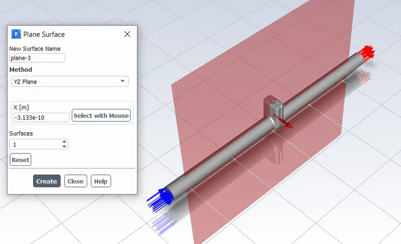
Flow-velocity contour graph option.
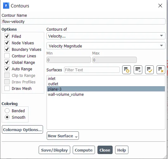
To calculate mass flow rate at the outlet report has been generated using following options.
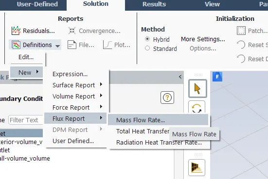
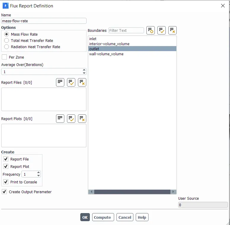
Animation for the fluid flowing inside fluid volume has also been created using following option.
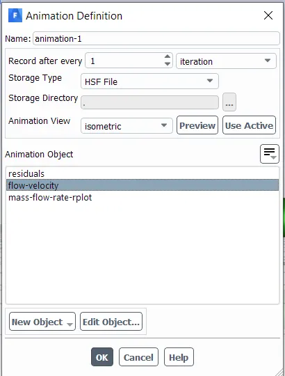
Results:
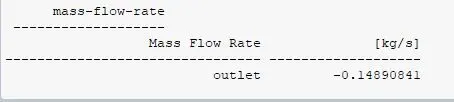
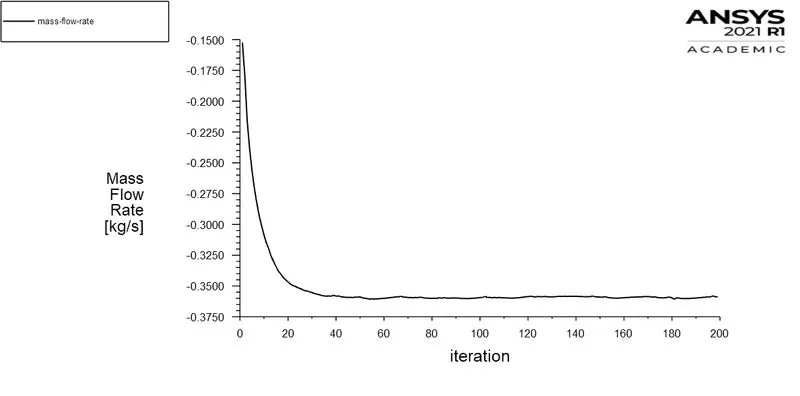
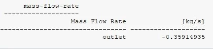
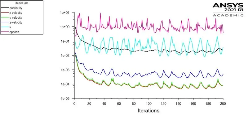
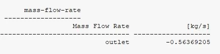
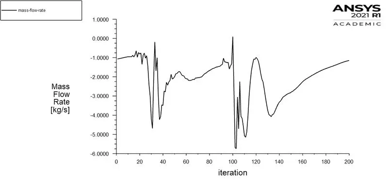
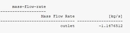
Mass flow rate for all simulated options is shown in beloe image. The negative sign shown before the mass flow rate indicates that the fluid going out of the volume.
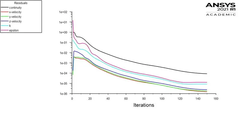
For 10mm Valve Opening Case:
Valve Opening
Residuals Graph
Flow velocity Contour
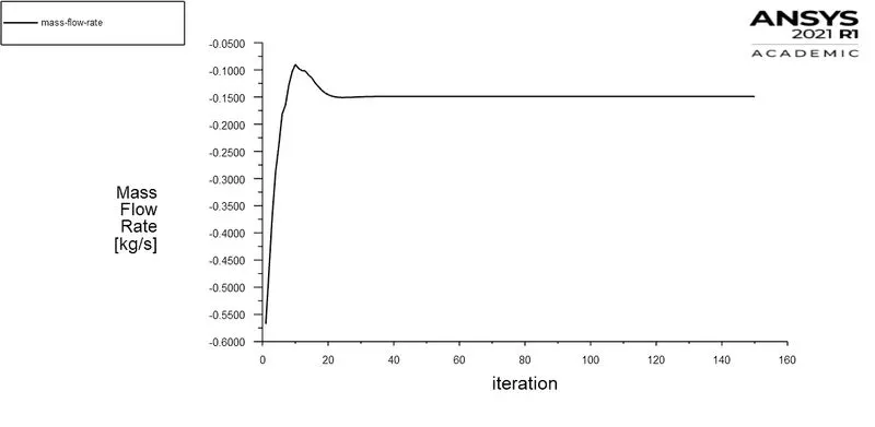
Mass Flow Rate
The negative sign in front of mass flow rate indicates that the fluid is going out of the simulated volume.
For 30mm Valve Opening Case:
Valve Opening
Residuals Graph
Flow velocity Contour
Mass Flow Rate
For 50mm Valve Opening Case:
Valve Opening
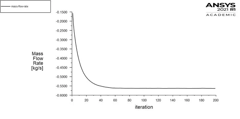
Residuals Graph
Flow velocity Contour
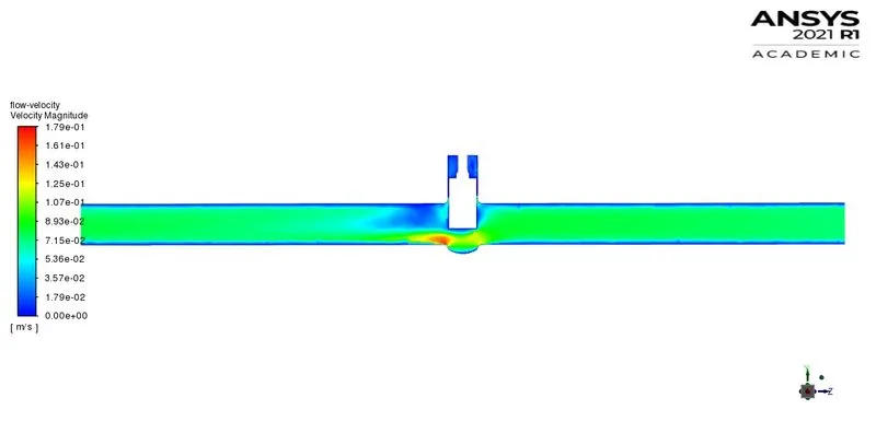
Mass Flow Rate
For 70mm Valve Opening Case:
Valve Opening
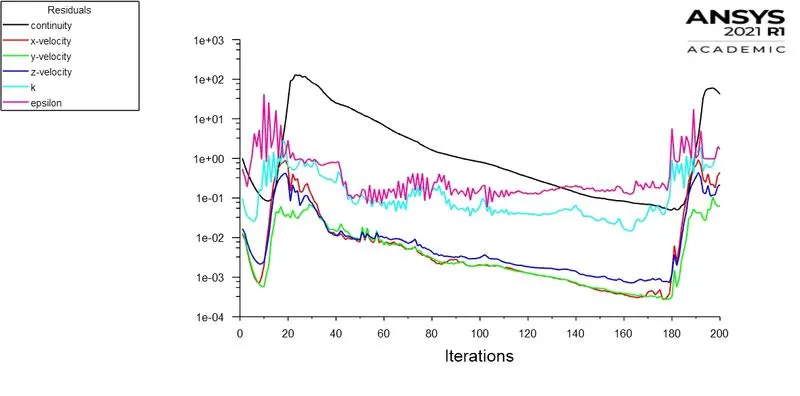
Residuals Graph
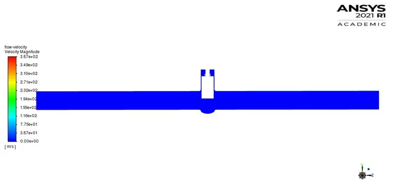
Flow velocity Contour
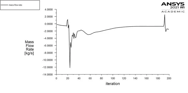
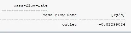
Mass Flow Rate
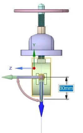
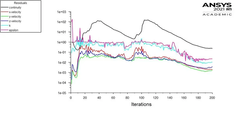
For 80mm Valve Opening Case:
Valve Opening
Residuals Graph
Flow velocity Contour
Mass Flow Rate
Calculate the flow coefficient and flow factor for each opening and plot the graph.
The flow coefficient of the valve is the efficiency of the gate valve to allow the fluid with respect to the opening. For gate valve, flow coefficient is the relation between the pressure drop between inlet & outlet and the related flow rate.
The equation is:
`C_v = Q*sqrt((SG)/(DeltaP)`
where,
Q = flow rate in gallons per minute ( 1 kg/s = 15.85 gpm)
`DeltaP` = Pressure drop across the valve in psi
SG = Specific gravity of fluid
For water,
SG = 1
`DeltaP` = 10 - 0 = 10 psi
To calculate Flow Factor,
`K_v = 0.865 * C_v`
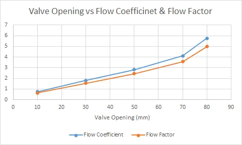
Following table shows the flow coefficient & flow factor for each opening condition simulated before.
| Valve Opening (mm) | Mass Flow Rate (kg/s) | Mass Flow Rate (gpm) | Flow Coefficient | Flow Factor |
| 10 | 0.148 | 2.3458 | 0.7418071 | 0.641663 |
| 30 | 0.359 | 5.69015 | 1.7993834 | 1.556467 |
| 50 | 0.563 | 8.92355 | 2.8218743 | 2.440921 |
| 70 | 0.822 | 13.0287 | 4.1200367 | 3.563832 |
| 80 | 1.147 | 18.17995 | 5.749005 | 4.972889 |
Discuss the results of the mass flow rate and flow coefficient.
- The mass flow rate is increases with the increase in the valve opening and also the flow coefficient of wach case & flow factor also increases as well.
- The graph compares the flow coefficient & flow factor with valve opening. It is clearly visible that the both quantity increases parallely with amount of opening.