Parametric study on Gate valve.
AIM:
To perform a parametric study on the gate valve simulation by setting the opening from 10% to 80%
OBJECTIVE:
1. Calculate the mass flow rate at the outlet for each design point
2. Calculate the flow coefficient and flow factor for each opening and plot the graph.
3. Analyse the results of mass flow rate and flow coefficient.
THEORY:
A gate valve, also known as a sluice valve, is a valve that opens by lifting a barrier (gate) out of the path of the fluid. Gate valves require very little space along the pipe axis and hardly restrict the flow of fluid when the gate is fully opened. The gate faces can be parallel but are most commonly wedge-shaped (in order to be able to apply pressure on the sealing surface).
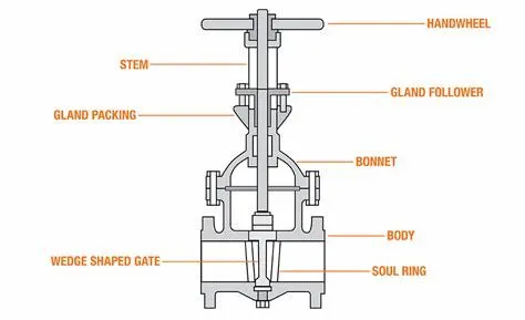
Gate valves are used to shut off the flow of liquids rather than for flow regulation. When fully open, the typical gate valve has no obstruction in the flow path, resulting in very low flow resistance. The size of the open flow path generally varies in a nonlinear manner as the gate is moved. This means that the flow rate does not change evenly with stem travel. Depending on the construction, a partially open gate can vibrate from the fluid flow.
Gate valves are mostly used with larger pipe diameters (from 2" to the largest pipelines) since they are less complex to construct than other types of valves in large sizes.
At high pressures, friction can become a problem. As the gate is pushed against its guiding rail by the pressure of the medium, it becomes harder to operate the valve. Large gate valves are sometimes fitted with a bypass controlled by a smaller valve to be able to reduce the pressure before operating the gate valve itself.
Gate valves without an extra sealing ring on the gate or the seat are used in applications where minor leaking of the valve is not an issue, such as heating circuits or sewer pipes.
In this project parametric study is performed at various valve position. mass flow rate is checked at various valve position.
Flow coefficient (Cv)
The flow coefficient of a device is a relative measure of its efficiency at allowing fluid flow. It describes the relationship between the pressure drop across an orifies valve or other assembly and the corresponding flow rate.
Mathematically the flow coefficient (or flow-capacity rating of the valve) can be expressed as
where
`K = Q sqrt(S_g/(DeltaP))`
Q is the rate of flow (expressed in US gallons per minute),
SG is the specific gravity of the fluid (for water = 1),
Delta P is the pressure drop across the valve (expressed in psi).
Flow factor (Kv)
When selecting the correct valve type and size, various operands can be decisive. For example, the Kv factor, the flow rate and the characteristic value for the pressure drop help you to choose the right valve for the desired requirements and applications.
What does the flow factor Kv indicate?
The Kv factor is a standardised key figure for the achievable flow rate of a fluid through a valve and has been in use since the 1950s. The Kv factor is calculated according to standard DIN EN 60 534, wherein the value is defined according to VDE/VDI 2173 guidelines by the measurement of water at a pressure drop of approx. 1 bar and a temperature of 5-30°C. The unit of the result is given in m3/h.
In addition, this characteristic value of the valve only represents a certain valve stroke, i.e. a specific degree of opening. A valve has as many Kv factors as it has setting levels. An on/off valve therefore only has one Kv factor while control valves have Kv factors for each position. The key figure for the maximum 100% stroke is the Kvs factor.
Difference between Cv value & Kv factor
The often equated Cv value is the US measurement unit, which is given in USG/min (US-Gallon per minute), and can therefore not be compared with the Kv factor. Conversion formulas exist for these values:
Kv = 0.857 * Cv
Cv = 1.165 * Kv
BODY OF THE CONTENT:
GEOMETRY PREPARATION:
For this project the CAD model of the gate valve is already prepared which can be found here.
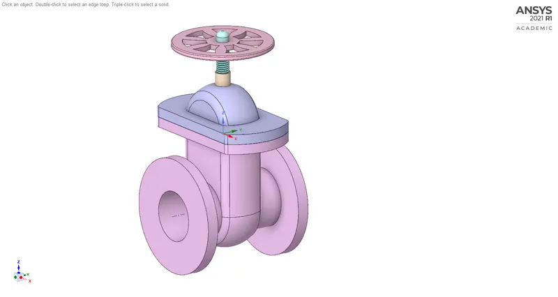
Geometry of valve
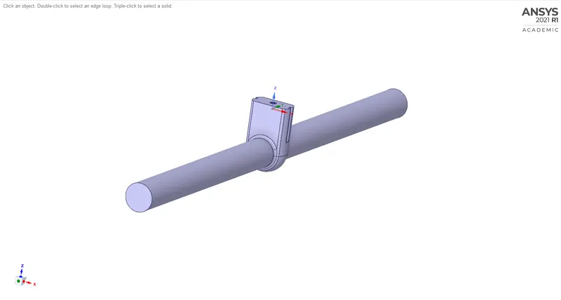
Fluid volume extraction
inlet and outlet extension is made for fully developed flow entrance in valve
Now to automate the calculation for all the lifts from 10% to 80% we set the input parameter as the valve lift initially we set it to 10 mm. This can be set in the group tab in the left side in the design tree.
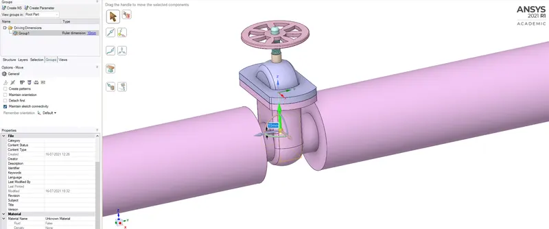
Once this is done now we can just change this input parameter and obtain results from the parameter menu in the workbench.
Note: For this project the valve is initially at a height of 10mm. So after doing the above lift of another 10mm the value will be at a height of 20mm
MESHING:
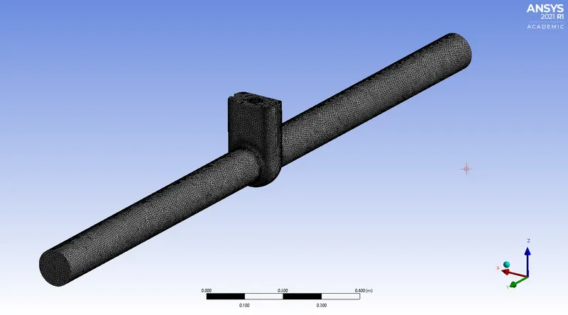
Meshing of gate valve. The total cell count is 413619.
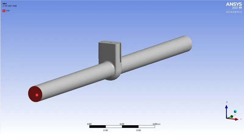
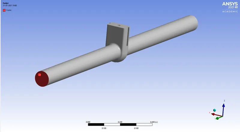
We also make some named selections.
Inlet
Outlet
CASE SETUP:
We open the fluent solver with 4 processors and double precision enabled. We choose a steady state, pressure based solver. We also enable gravity in the negative Z direction with a value of 9.81 m/s.
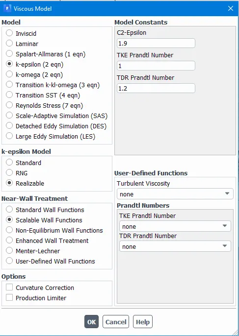
we choose the k-epsilon realizable model with the following options.
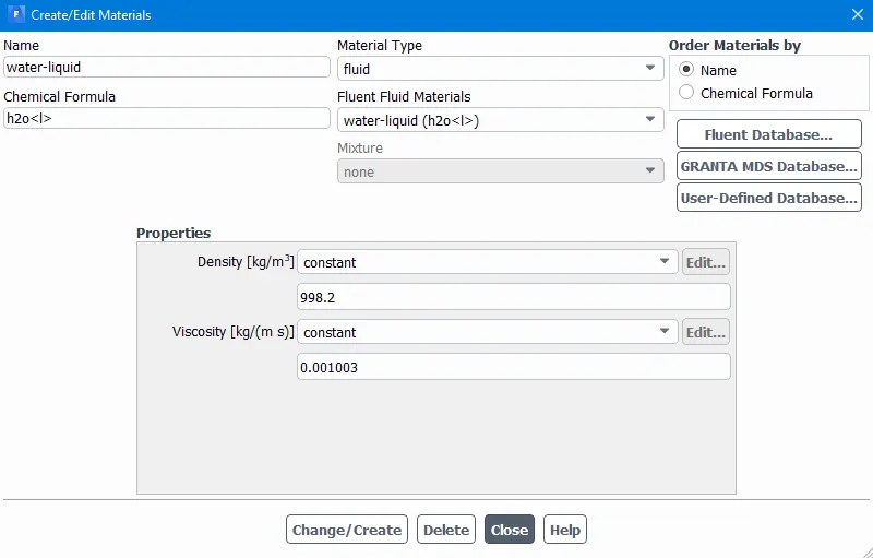
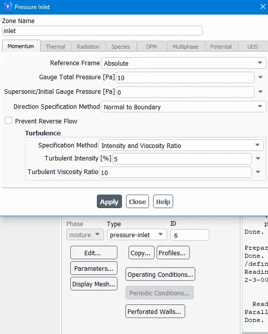
The fluid used in this case is water. we give the following boundary condition
1. Inlet = Pressure inlet 10 pascal
2. Outlet = Pressure outlet 0 pascal
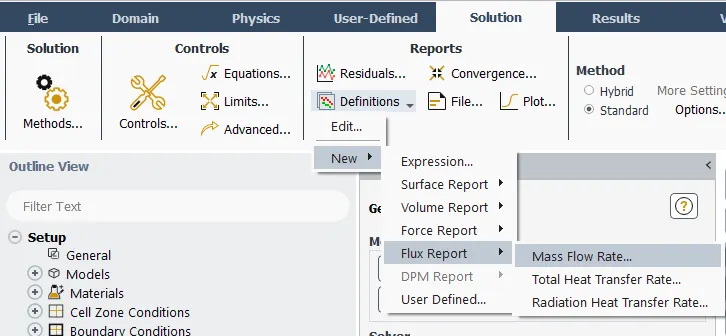
Now we can set some outpt parameters for the parametric study. For this we require mass flow rate which can be found in the solution tab as shown below.
As for the other parameters. we need inlet pressure, outlet pressure from which we calculate the delta p and from which we can calculate the flow coefficient from which we calculate the flow factor.
Inlet pressure, Outlet pressure can be found in the options as shown in the picture below.
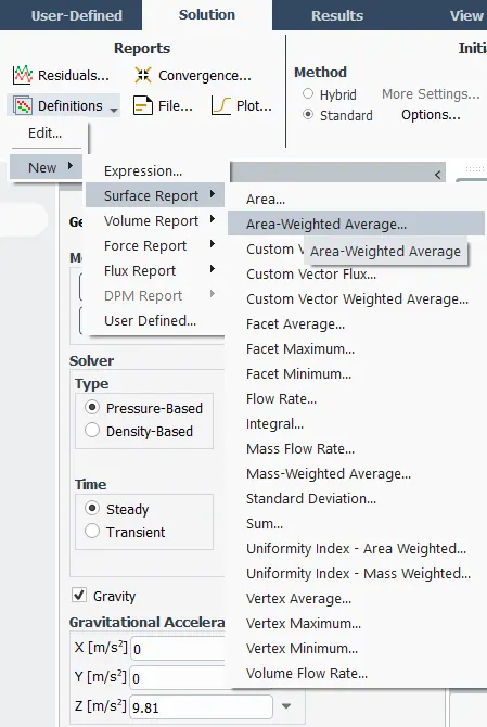
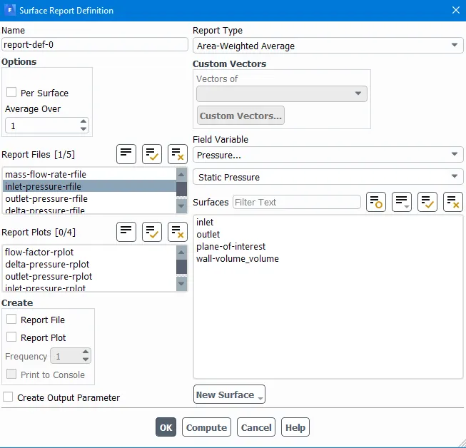
In the area weighted average we create the inlet and outlet pressure parameters and then if required we check the create output parameter. This will be sent to the parameter menu at the workbench.
For delta p we have the expression tab
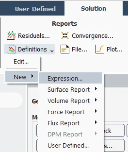
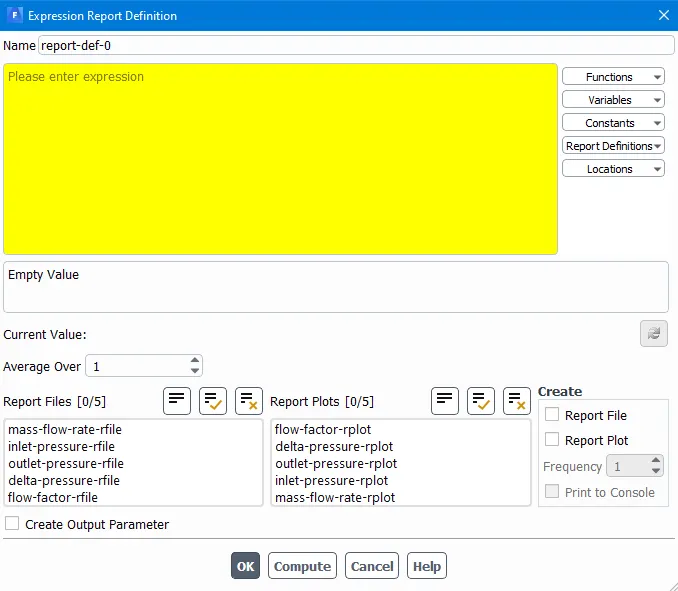
In the yellow space provided we write the expression inlet pressure - outlet pressure and name it as deltap. Using the same method we create another parameter using mass flow rate ,deltap. Since Sg of water is 1 we write "mass-flow-rate*(1/deltap)^(1/2)" and check the create output parameter option. Similarly we create flow factor using "0.856*flow coefficient".
next, we select the standard hybridisation with the compute from inlet option. The number of iterations will be set to 250. Once everything is in place we run the simulation to get the following results
RESULTS:
For a lift of 10 mm.
Residuals
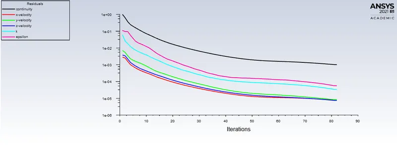
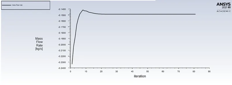
mass flow rate
Console output
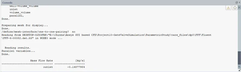
It is to be observed that the mass flow rate is negative. This is because fluent assumes that the mass coming inside the CV is positive and the mass exiting the CV is negative.
Parametric Study
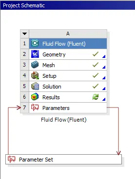
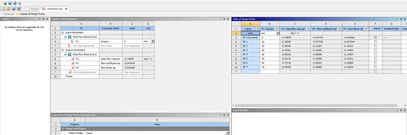
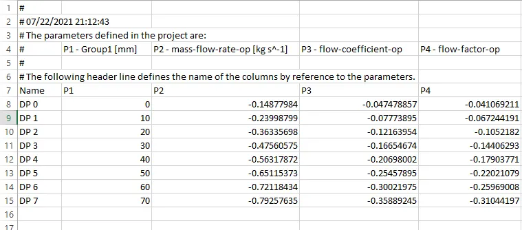
in the parametric study, we change the opening of the valve from 10% to 90% and see the mass flow rate varies with respect to valve opening. This can be done in the parameter tab under the workbench module. Here on the left side we will have a table. Initially we will have Dp 0 with the 1st parameter which is the valve height as 0mm. Here we enter values from 0 to 70 and select the update all design points. This will calculate all the mass flow rates and flow coefficients and list them out in the tabular form as shown above.
We can export the above data into a CSV file to get some meaning full results.
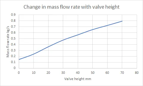
Mass flow rate Vs Valve position
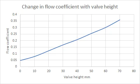
flow coefficient Vs Valve opening
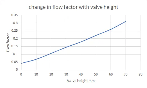
Flow factor Vs Valve opening
CONCLUSION:
From the above results it is ibserved that
- As the height of the opening increases the mass flow rate increases, as it would in real life.
- As the mass flow rate increases the flow coefficient and flow factor increase as they are directly proportional to the mass flow rate.