Week 9 - Parametric study on Gate valve.
Aim:
- Obtain the mass flow rates at the outlet for each design point.
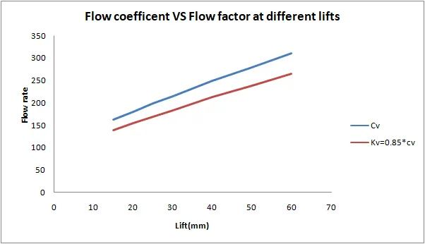
- Calculate the flow coefficient and flow factor for each opening and plot the graph.
- Discuss the results of the mass flow rate and flow coefficien
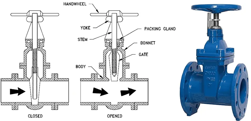
Gate valve:
1.Gate valves are used to shut off the flow of liquids rather than for flow regulation. When fully open, the typical gate valve has no obstruction in the flow path
2.The size of the open flow path generally varies in a nonlinear manner as the gate is moved. This means that the flow rate does not change evenly with stem travel. Depending on the construction, a partially open gate can vibrate from the fluid flow.
3.Gate valves are mostly used with larger pipe diameters (from 2" to the largest pipelines) since they are less complex to construct than other types of valves in large sizes.
4.At high pressures, friction can become a problem. As the gate is pushed against its guiding rail by the pressure of the medium, it becomes harder to operate the valve. Large gate valves are sometimes fitted with a bypass controlled by a smaller valve to be able to reduce the pressure before operating the gate valve itself.
5.Gate valves without an extra sealing ring on the gate or the seat are used in applications where minor leaking of the valve is not an issue, such as heating circuits or sewer pipes
`
Geometry: (without parametric study)
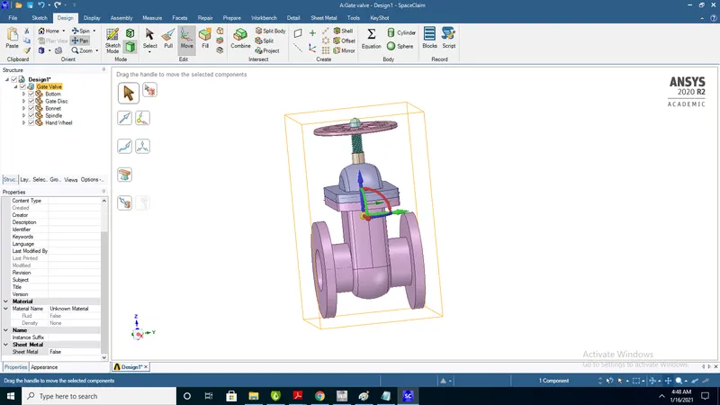
1.Import gate valve geometry to space cliam
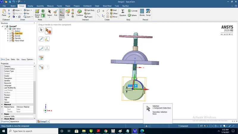
2. 1.hiding of bottom of gate valve inorder to raise of 10mm to gate disk
3.Select component and select bottom part type 10mm
4. extract fluid volume by selecting edges
5.select inlet,outlet and edge under Bonnet
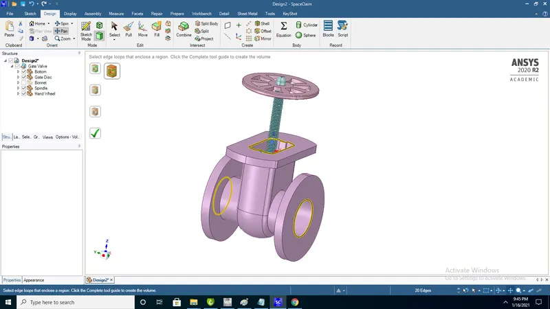
6. use pull option to extend inlet and outlet
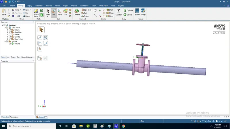
7. Supress physics for solid geometry
Meshing:
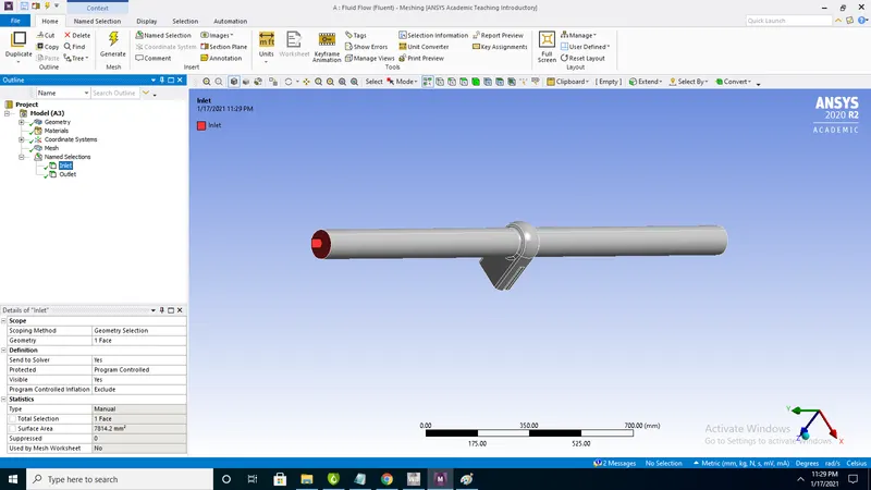
Named selections:
1)Inlet
2)Outlet
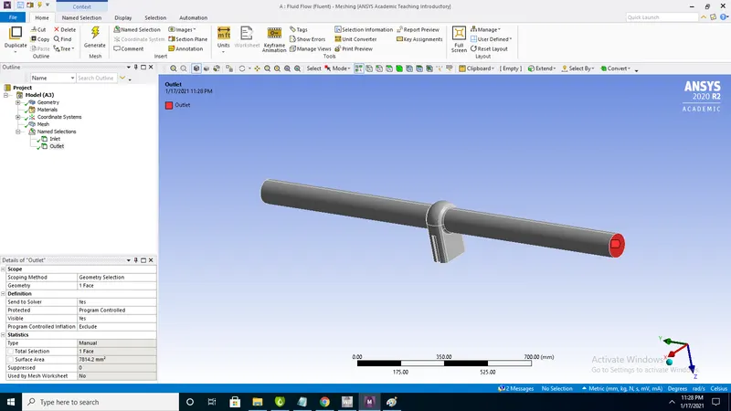
1.After named selections update mesh
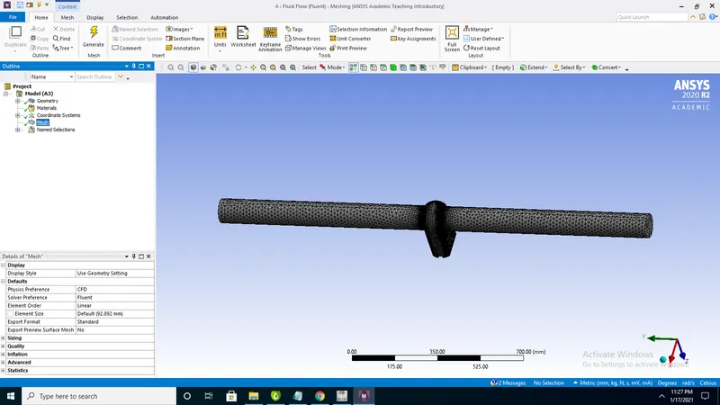
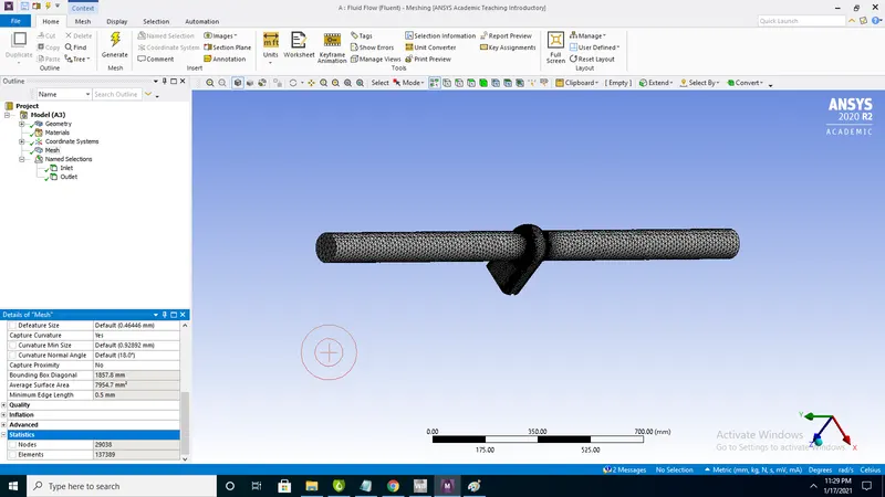
Stastics:
1.Total no of elements 137389
Quality: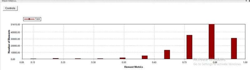
Setup:
Setup:
1)General
Type: Pressure-based
Time: steady
Velocity formulation: Absolute
2D Space : Planar
Enable gravity and Z=-9.81m/s2
2)Models:
Viscous: Turbulent K-epsilon-realizble-Scalable wall funcion
K-Epsilon model is used for problems which having higher reynolds number
3)Materials:
Fluid= Water
Solid= Aluminium
4)Boundary conditions:
Pressure inlet: Gauge pressure =10pa
5)REport-definations-mass flow rate -outlet
6)create plane and select on inlet plane and create
7)Contours-New-Velocity-filled-Plane
8)create-solution animation-contour1
9)no of iterations 250
Contours:
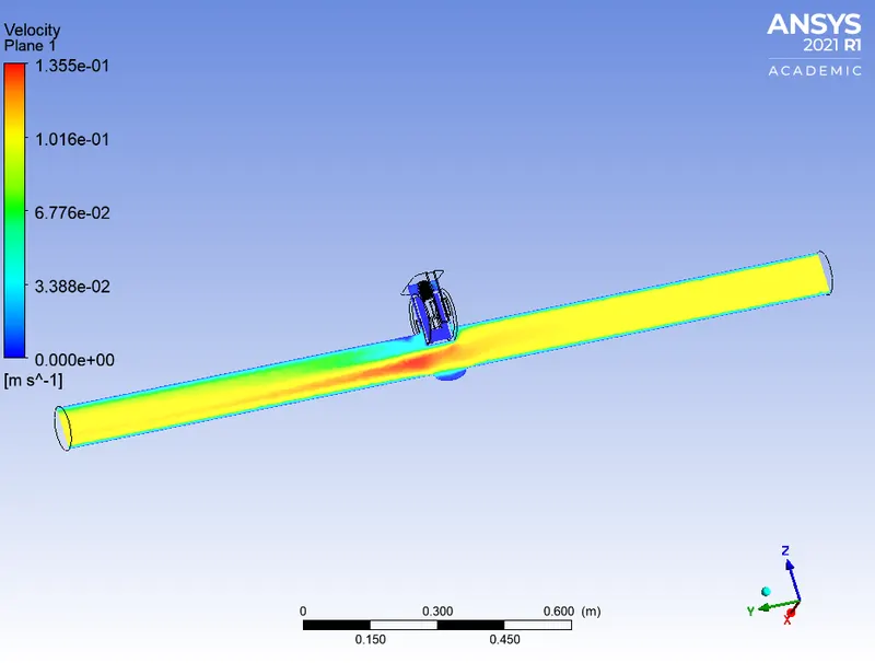
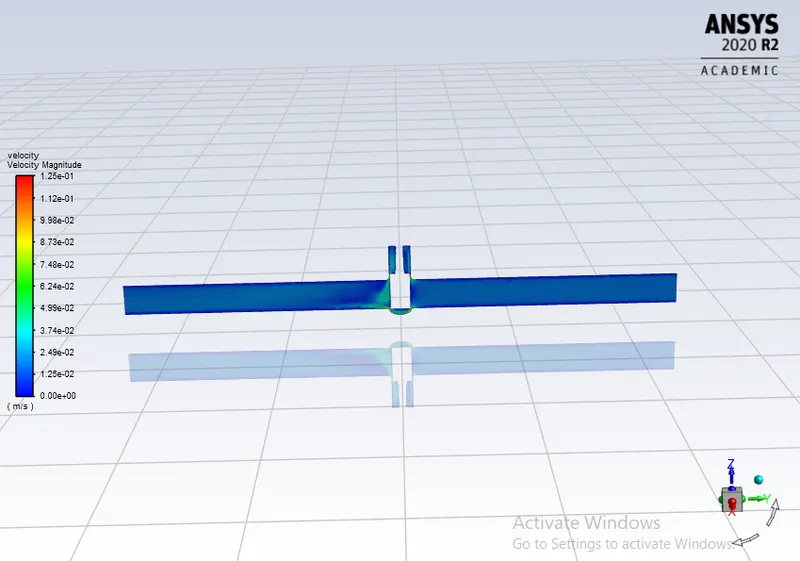
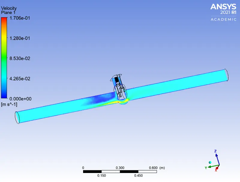
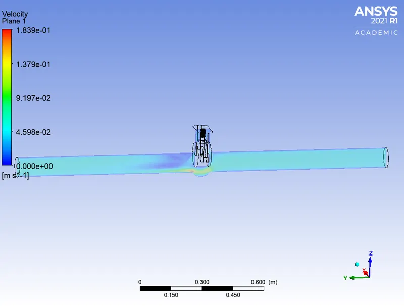
1)Velocity contour at plane
Geometry:
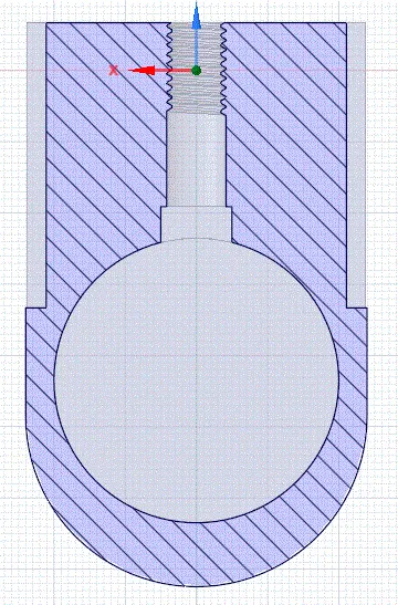
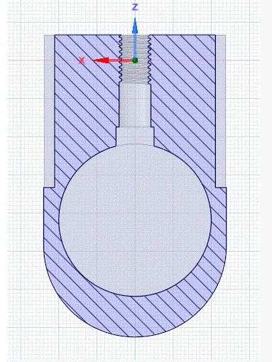
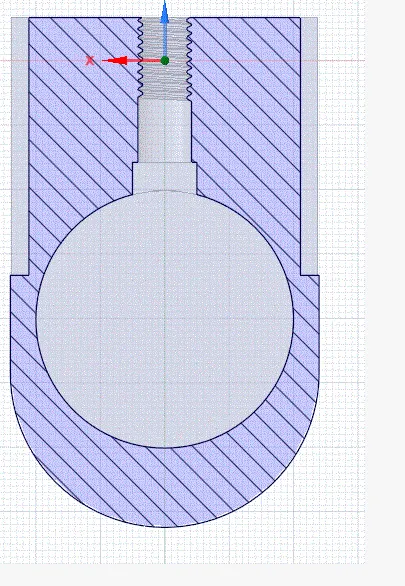
1.Parametrise geometry and update current for every lift to get mas flow rates.
2. Geometry at 15mm lift
3.Geometry at 20mm lift
3.Geometry 25mm lift
Refinment of mesh:
Details:
Element size=10mm
Elements:189975
Nodes:39652
Setup:
1.Setup is same for both baseline and refined mesh
2.K-epsilon is used as reynolds number is 14087 morethan 2000 and flow is turbulent
Results:
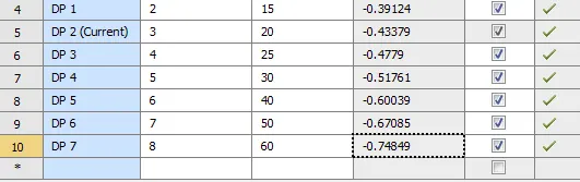
Flow corefficent:
1.The flow coefficient of a device is a relative measure of its efficiency at allowing fluid flow.
2.It describes the relationship between the pressure drop across an orifice valve or other assembly and the corresponding flow rate
Mathematically the flow coefficient Cv (or flow-capacity rating of valve) can be expressed as :

where:
- Q is the rate of flow (expressed in US gallons per minute),
- SG is the specific gravityt of the fluid (for water = 1),
- ΔP is the pressure drop across the valve (expressed in psi)
Flow factor:
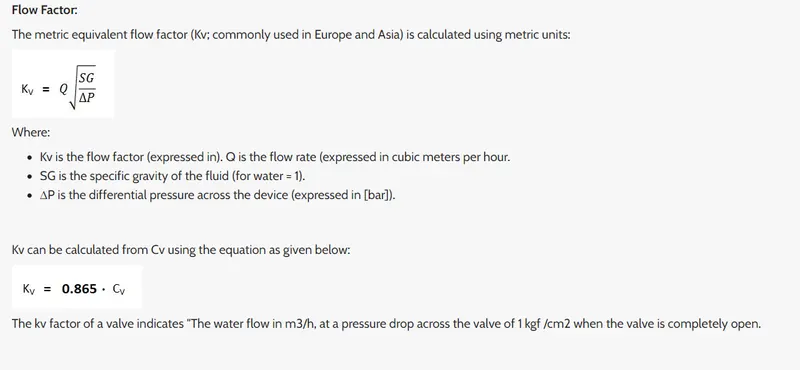
Table1:
| Lift(mm) | Q (Gallon/Min) | SG | Dp(Psi) | Cv | Kv=0.85*cv |
| 15 | 6.2 | 1 | 0.001450377 | 162.7987918 | 138.3789731 |
| 20 | 6.88 | 1 | 0.001450377 | 180.6541432 | 153.5560217 |
| 25 | 7.57 | 1 | 0.001450377 | 198.7720732 | 168.9562623 |
| 30 | 8.2 | 1 | 0.001450377 | 215.3145311 | 183.0173515 |
| 40 | 9.52 | 1 | 0.001450377 | 249.9749191 | 212.4786812 |
| 50 | 10.63 | 1 | 0.001450377 | 279.1211544 | 237.2529812 |
| 60 | 11.86 | 1 | 0.001450377 | 311.418334 | 264.7055839 |
Plot1:
Observations:
1.With increase in lift of valve mass flow rate,flow coefficent increases
2. lift of disc is propontal to mass flow rate and flow coefficent
3.From it is clear that mass flow rate and flow coefficent increases with height
Velocity contours:
!.For 15mm lift
2)For 20mm lift
2)For 25mm lift
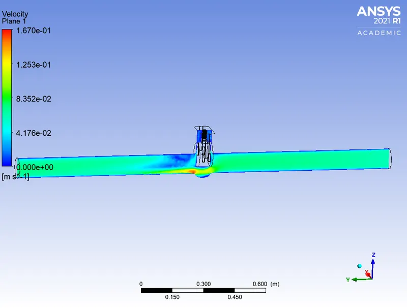
3)2)For 30mm lift
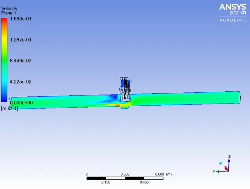
4)For 40mm lift
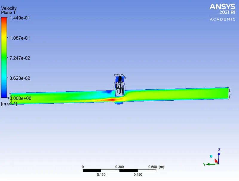
5)2)For 50mm lift
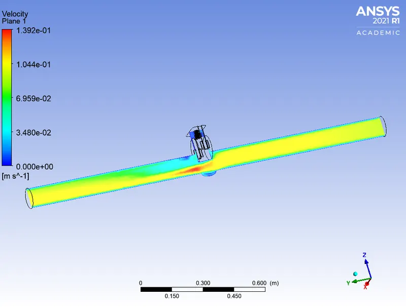
6)2)For 60mm lift