Week 9 - Parametric study on Gate valve.
AIM: Parametric study on Gate valve.
OBJECTIVE:
To perform a parametric study on the gate valve simulation by setting the opening from 10 % to 80%.
- Obtain the mass flow rates at the outlet for each design point.
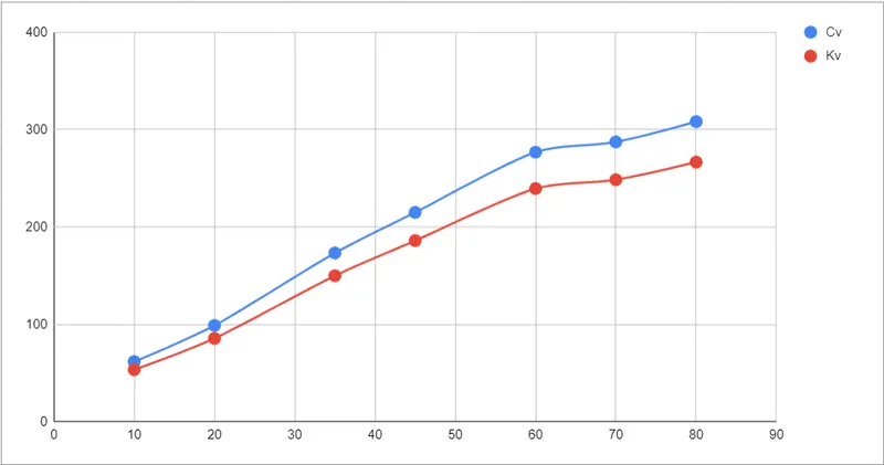
- Calculate the flow coefficient and flow factor for each opening and plot the graph.
- Discuss the results of the mass flow rate and flow coefficient.
Introduction:
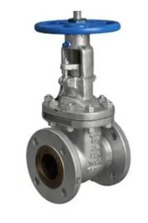
WHAT IS GATE VALVE?
A gate valve is the most common valve type found in water supply systems. It represents a linear-motion isolation valve and has a function to stop or allow the flow. Gate valves got their name from the closure element sliding into the flow stream to provide shutoff and, therefore, acting like a gate. Gate valves are used to isolate specific areas of the water supply network during maintenance, repair works, new installations, as well as to reroute water flow throughout the pipeline.
A gate valve controls the media's flow by lifting the gate (open) and lowering the gate (closed). A gate valve's distinct feature is the straight-through unobstructed passageway, which induces minimal pressure loss over the valve. The unobstructed bore of a gate valve also allows for a pig's passage in cleaning pipe procedures, unlike butterfly valves. Gate valves are available in many options, including various sizes, materials, temperature and pressure ratings, and gate and bonnet designs.
Gate valves tend to be slightly cheaper than ball valves of the same size and quality. They are slower in actuation than quarter-turn valves and are for applications where valve operation is infrequent, such as isolating valves. Gate valves should be used either fully open or fully closed, not to regulate flow. Automated gate valves exist with either an electric or pneumatic actuator, but a manual gate valve is cost-effective since they have infrequent usage.
Functioning priniciple:
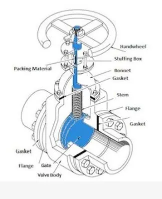
A gate valve's main components are body, seat, gate, stem, bonnet, and actuator (Figure 2). The primary operation mechanism is straightforward. Turning the handwheel rotates the stem, which moves the gate up or down via the threads. They require more than one 360° turn to fully open/close the valve. Lifting the gate from the path of the flow, the valve opens. Lowering the gate to its closed position seals the bore resulting in a full closure of the valve.
For a gate valve, the relationship between the gate's vertical travel and the flow rate is nonlinear, with the highest changes occurring near shutoff. When used to regulate flow, the relatively high velocity of the flow at partial opening results in gate and seat wear, which along with possible vibrations of the gate, shortens the valve's service life.
Gate valve design and types:
Bonnets:
A bonnet protects the internal parts of a gate valve . It is screwed in or bolted to the valve body, creating a leak-proof seal. Therefore, it is removable for repair or maintenance purposes. Depending on applications, gate valves can have screw-in, union, bolted, or pressure seal bonnets
Screw in bonnets:
Screw-in bonnets are the simplest in construction. They are common in small size valves and provide a durable leak-proof seal. figure 1 shows a gate valve with a screw-in bonnet on the left.
Union bonnets:
Union bonnets are held in place by a union nut. The union nut sits on the lower edge of the bonnet and screws into the valve body's threads. This type of design ensures that the leak-proof seal created by the nut does not deteriorate by frequent removal of the bonnet. Therefore, union bonnets are common for applications that require regular inspection or maintenance.
Bolted bonnets:
Bolted bonnets provide sealing in larger valves and higher pressure applications. In this type, the bonnet and valve body are flanged and bolted together. Figure 1 shows a gate valve with a bolted bonnet on the right.
Pressure seal bonnets:
Pressure seal gate valves are ideal for high-pressure applications (more than 15 MPa). This type of construction uses internal pressure to create a better seal. Pressure seal bonnets have a downward-facing cup inserted into the valve body. When internal fluid pressure increases, the cup's forced outward, improving the seal.
Gates:
The gate comes in a variety of designs and technologies to produce effective sealing for differing applications.
Parallel slide gates:
Gate valves can also come in a parallel form where the gate is flat, and the seats are parallel. Parallel gate valves use line pressure and positioning to make a tight seal. Flat gates consist of two pieces and have a spring in the middle. The spring pushes the pieces towards the seats for enhanced sealing. Due to their inherent design, parallel gate valves have a safety advantage in higher temperature applications. In wedge-shaped gate valves, an additional compression load on the seats may result in thermal binding and restricted opening of the valve due to expansion. Furthermore, since there is no wedging action in parallel gates, closing torques are comparatively smaller, resulting in smaller, less expensive actuators or less manual effort. Due to their sliding into position, parallel gates keep dirt away from the seating surfaces.
Analysis:
- Here we will perform simulation for a Gate Valve and see the effect of lifting the Gate Disc at different amount of percentage from 10 % to 80%.
- With the help of Parametric option, for lift of Gate Disc, we can parameterized the lift amount and see the different results or changes with different lift percentages.
- Once we study for 10% of lift, we will parameterize the lift and perform the analysis.
- Then we will see the changes in contours and other variable like Mass flow rate, Flow coefficient and Flow factor for all results one by one.
Geometry:
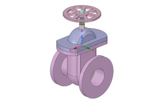
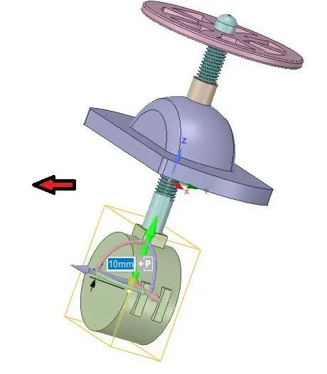
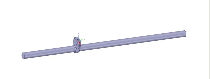
- Here we can see the Green color arrow in upward direction shows the movement of “Gate Disc” in Positive Z-Direction.
- Also we can see the symbol of “P”.
- This symbol “P” is used to parameterize the lift of the “Gate Disc”.
- After selecting the symbol “P”, it turns in Grey color, and message shows that a Group has been created for lift.
- Created group for the lift parameter shown in above image.
- On the left side, in Tree structure, if we see the Group options, we can see created group and the amount of parameter, which has been set 10 mm lift.
- We can simply change the value of parameter from there directly.
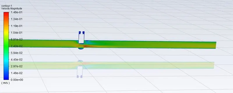
- After lifting the “Gate Disc”, move the both face at inlet and outlet of the “Bottom” part by amount of 400mm and 800 mm just to see the fluid flow and its effects as given below:

Meshing:
Details:
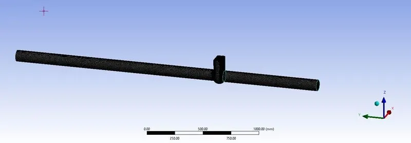
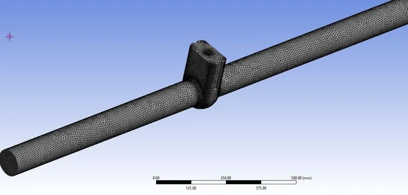
- Element Size: 8 mm
- Elements: 322188
- Nodes: 66674
- After Meshing, update it for further process and go for the Fluent Setup.
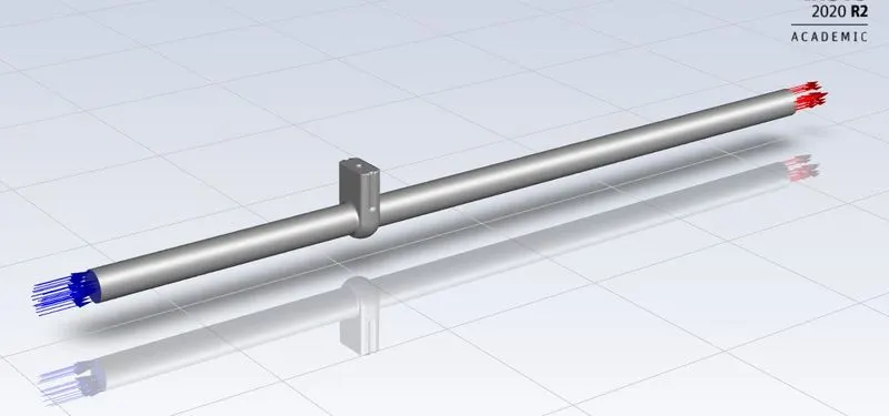
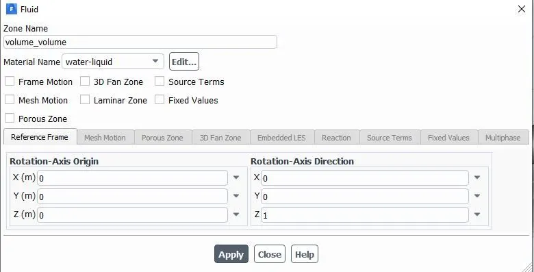
In Fluent Setup, necessary details for simulation are as described below:
Case Setup Details:
General Settings:
Analysis type: Steady state
Solver: Pressure based solver
Gravity: -9.81 m/s2 in Z-Direction
Material Specifications:
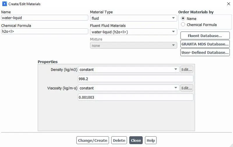
Material: water-liquid (h2o)
Chemical Formula: H2O
Density: 998.2 Kg/m3
Viscosity: 0.001003 Kg/ (m-s)
Viscous Model:
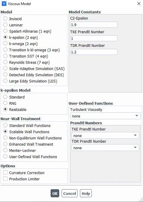
Model: K-Epsilon
K-Epsilon Model: Realizable
Near Wall Treatment: Scalable Wall Functions
Boundary Conditions:
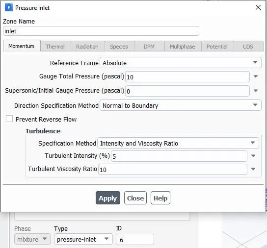
Inlet: >Type: Pressure-Inlet
>Gauge Total Pressure: 10 Pa
Outlet: >Type: Pressure-outlet
>Gauge Total Pressure: 0 Pa
Wall: >Type: Wall
>Wall Motion: Stationary Wall
>Shear Condition: No Slip
Interior: >Type: Interior
NOTE:
- Here we have taken Pressure for inlet = 10 Pa.
Typically for Pipe flow, pressure of 10 Pa is acceptable.
- In Viscous model, we have taken K-Epsilon model.
- The Reason behind choosing the K-Epsilon Viscous model is characteristic of the flow, which is turbulent.
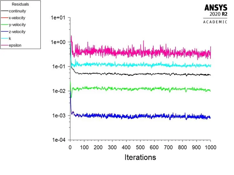
- For Reynolds No. about 2000 and more, flow is turbulent. So we have taken K-Epsilon Viscous model.
- But here, we have given Pressure Inlet, instead of Velocity Inlet. So knowing the velocity of the flow for correct Reynolds No. is required.
- So, to know the velocity of the flow, we have to go for initializing the solution.
- So, go to Solution, and select Standard Initialization, and Initialize from Inlet.
- After initialization, we can get the correct velocity and calculate the Reynolds No. and from that, we can decide for the appropriate viscous model.
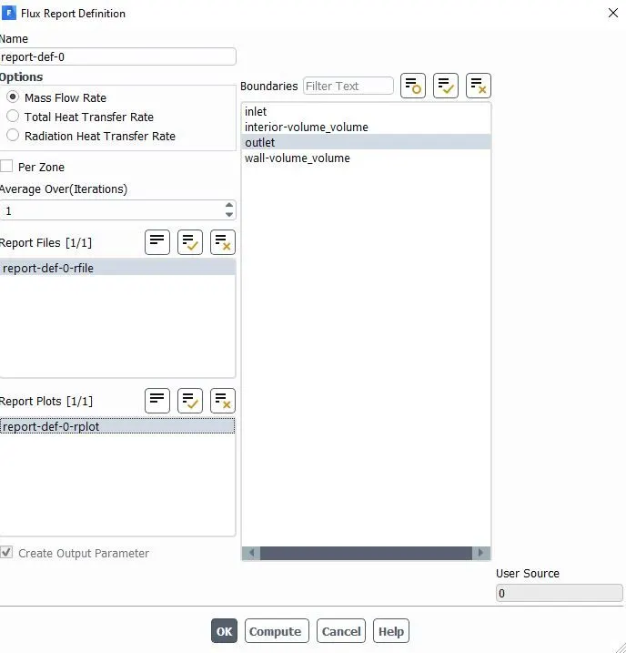
Parametric study:
- In above image we can see the Parameterization of the Lift Parameter before and after Simulation.
- We can see the Parameter Set for the study at different Design Points of Lift of Gate Valve.
- On completion of the simulation, select “Parameter Set” and give input for different Design Points.
- Then Update all Design points and check all the results of different Design points.
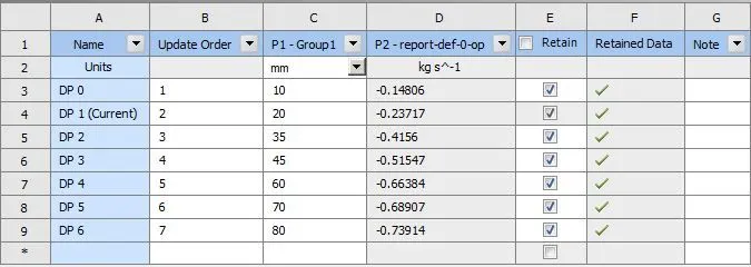
- In above image, we can see Mass Flow Rate before and after Updating all Design Points.
- Before Update, we have to give different inputs for the Lift of Gate Disc as 10,20, 35, 45,60,70 and 80 mm and also select the all check boxes in Retain column for all Design Points.
- Then select on “Update All Design Points”.
We can see in above image that after updating all Design Points, results of the Mass Flow Rate for all Design Points generated automatically.
- These results are calculated by fluent based on the lift of the “Gate Disc”.
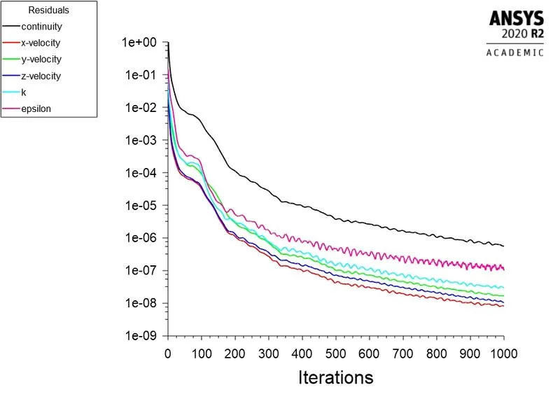
- Now we can check all Design Points one by one for detailed results like Pressure and Velocity Contours, Residuals etc. by selecting each Design Point and making it as “Current”.
Results:
Now we will see all cases of lift of “Gate Disc” from 10% to 80% one by one.
- We will discuss each case particularly, for all type of results and calculate Flow coefficient and Flow Factor accordingly.
- Here we will see Mass Flow Rate at Outlet, Flow Coefficient and Flow Factor and required Plots for each opening.
Flow Coefficient:
The flow coefficient of a device is a relative measure of its efficiency at allowing fluid flow. It describes the relationship between the pressure drop across an orifice valve or other assembly and the corresponding flow rate.
Mathematically the flow coefficient Cv (or flow-capacity rating of valve) can be expressed as:
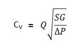
Where:
- Q is the rate of flow (expressed in US gallons per minute).
- SG is the specific gravity of the fluid (for water = 1).
- ΔP is the pressure drop across the valve (expressed in psi).
In more practical terms, the flow coefficient Cv is the volume (in US gallons) of water at 60 °F that will flow per minute through a valve with a pressure drop of 1 psi across the valve.
The use of the flow coefficient offers a standard method of comparing valve capacities and sizing valves for specific applications that is widely accepted by industry. The general definition of the flow coefficient can be expanded into equations modeling the flow of liquids, gases and steam using the discharge coefficient.
Flow Factor:
The metric equivalent flow factor (Kv; commonly used in Europe and Asia) is calculated using metric units:
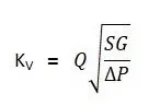
Where:
- Kv is the flow factor (expressed in). Q is the flow rate (expressed in cubic meters per hour.
- SG is the specific gravity of the fluid (for water = 1).
- ∆P is the differential pressure across the device (expressed in [bar]).
Kv can be calculated from Cv using the equation as given below:
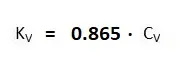
The kv factor of a valve indicates "The water flow in m3/h, at a pressure drop across the valve of 1 kgf /cm2 when the valve is completely open.
Cases:
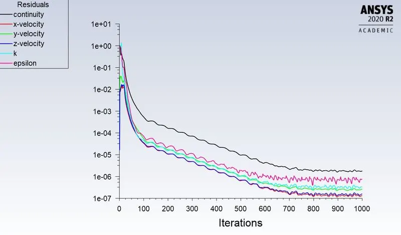
GV1:10mm:
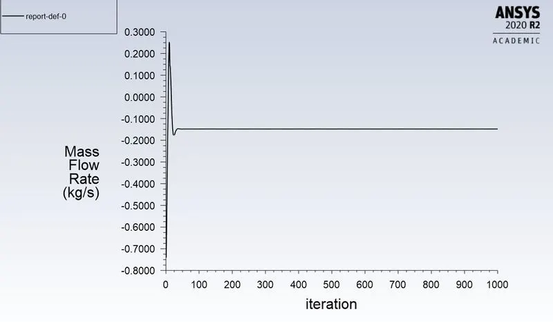
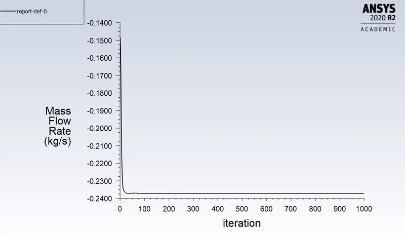
Mass flow rate:
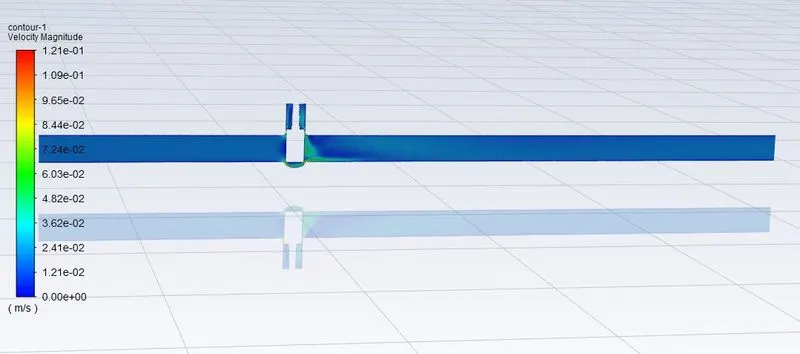
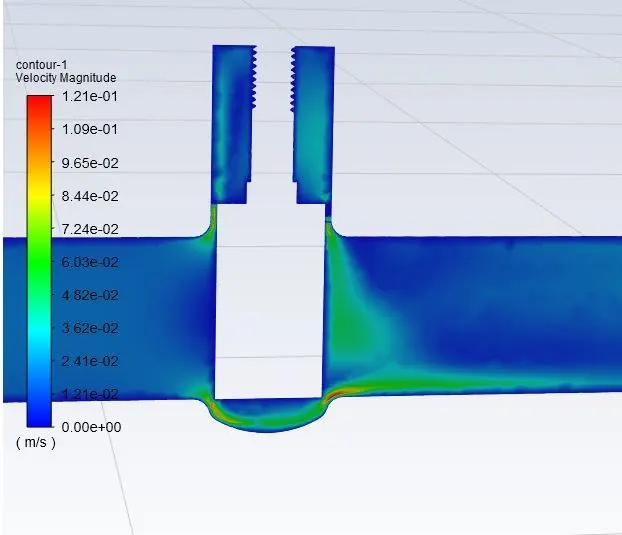
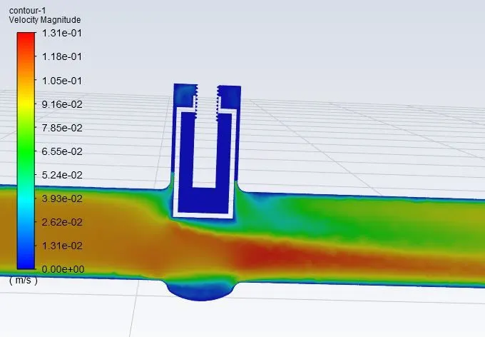
Velocity contour:
GV2:20mm:
GV3:35mm:
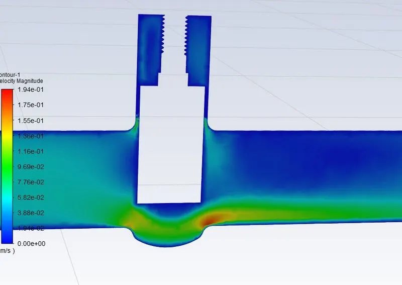
GV4;45mm;
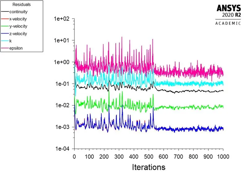
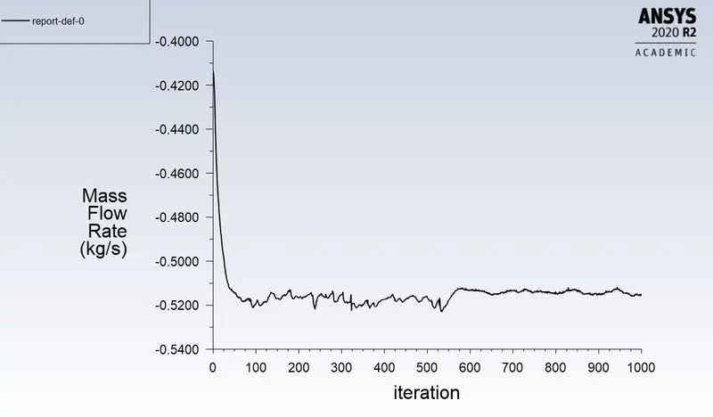
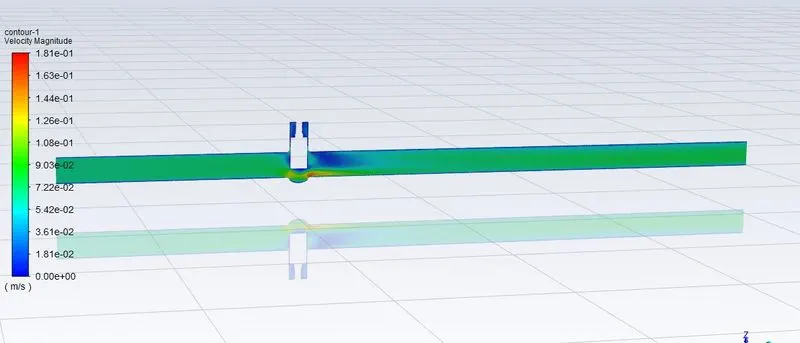
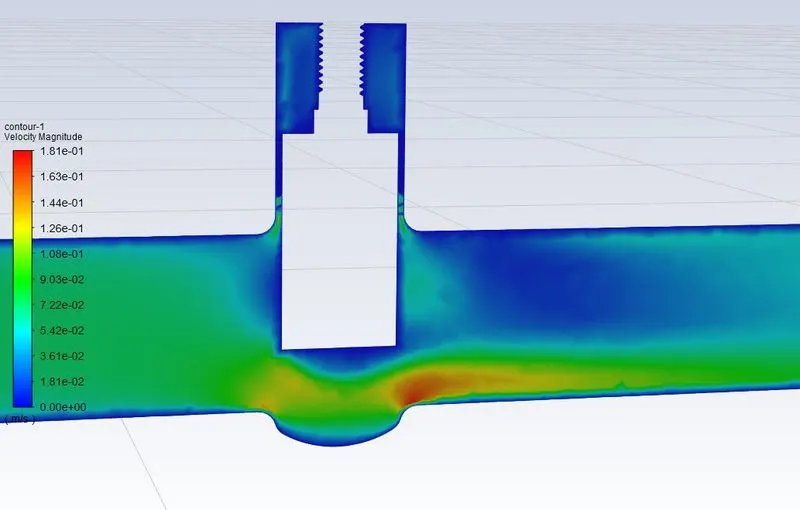
GV5:60mm:
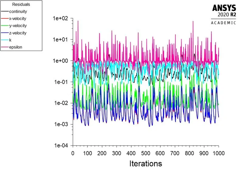
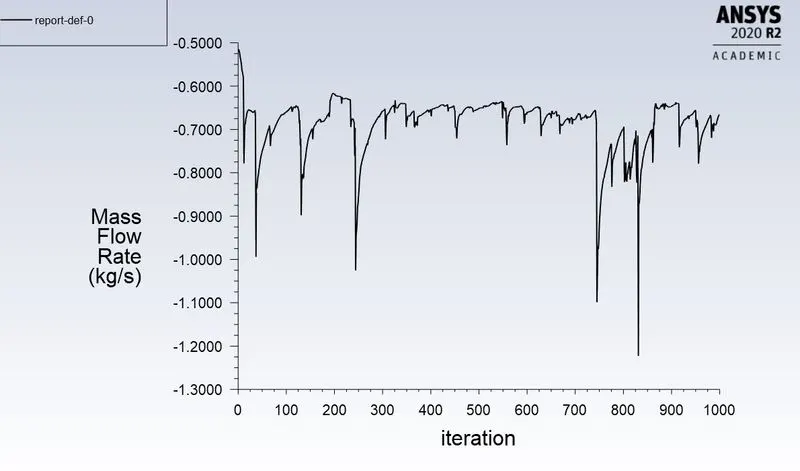
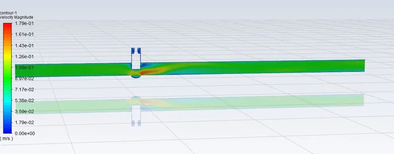
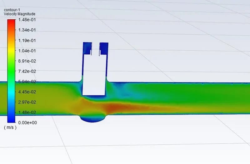
GV6:70mm:
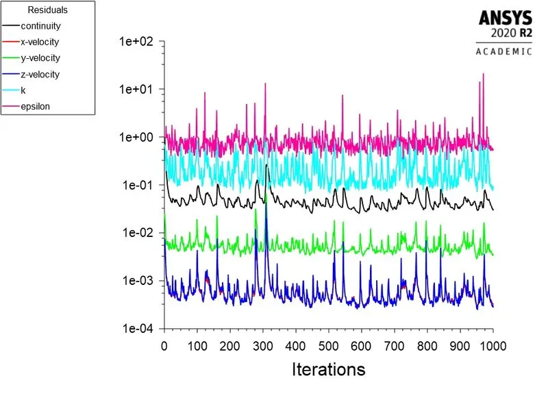
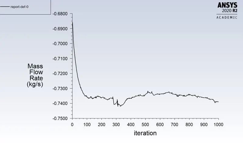
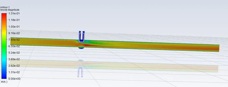
GV7:80mm:
Observations:
| Cases | mass flow rate | gate disc lift (mm) | flow co-efficient(Cv) in gpm/psi | flow factor(Kv) in m^3hr^-1 |
| Gv1 | 0.14806 | 10 | 61.730 | 53.397 |
| Gv2 | 0.23717 | 20 | 98.884 | 85.535 |
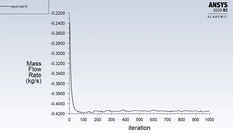
| Gv3 | 0.4156 | 35 | 173.277 | 149.885 |
| Gv4 | 0.51547 | 45 | 214.916 | 185.903 |
| Gv5 | 0.66384 | 60 | 276.778 | 239.413 |
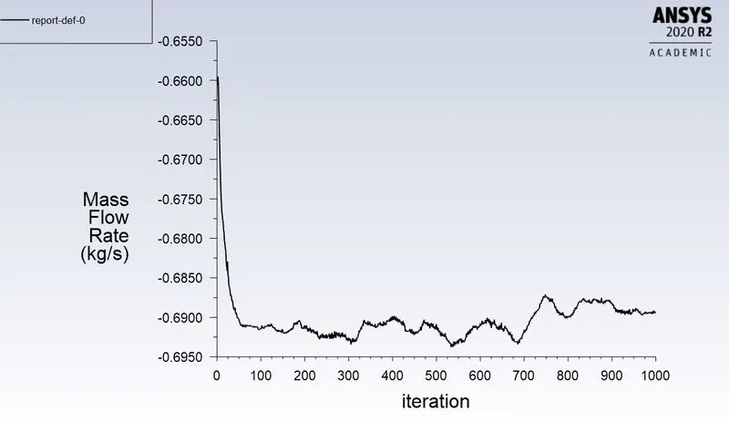
| Gv6 | 0.68907 | 70 | 287.297 | 248.512 |
| Gv7 | 0.73914 | 80 | 308.173 | 266.570 |
Graph:
Conclusion:
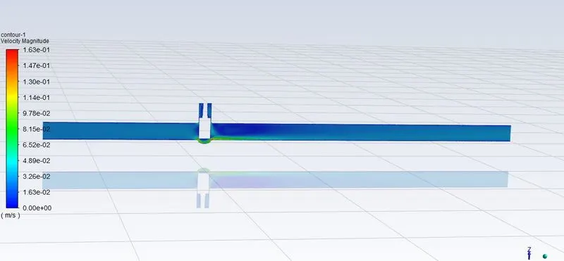
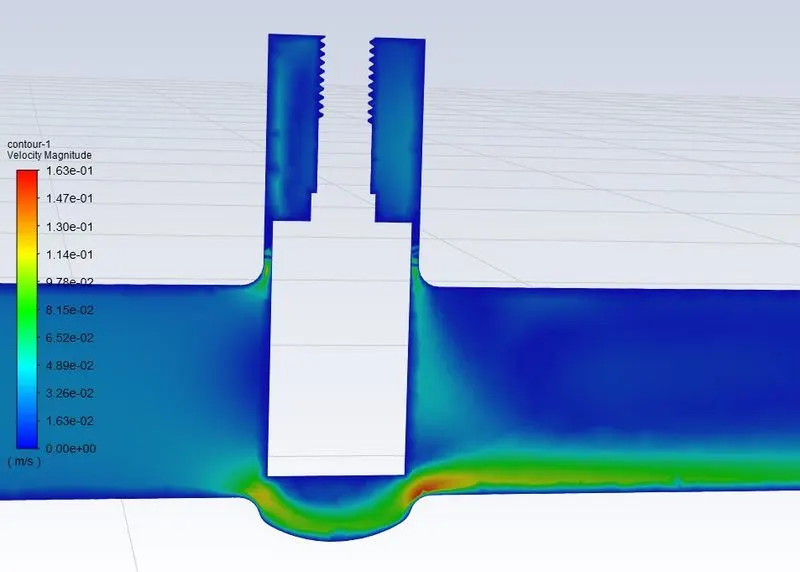
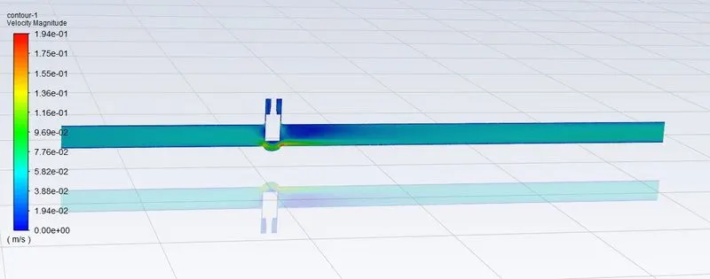
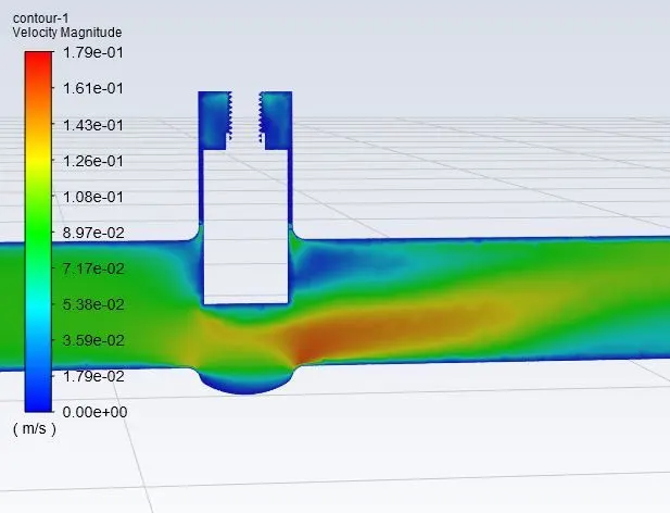
- We can conclude from observations that velocity in the first case is very low. As opening or lift of the Gate Disc increases, velocity of the flow increases.
- We can observe that at the front or inlet side of the valve, pressure is high. As flow passes through the valve opening, it decreases.
- And at the outlet there are no any restrictions to the flow, so pressure becomes 0.
- It means there is minimum Pressure Drop.
- There is a gradual increase in Mass Rate, Flow Coefficient and Flow Factor as Lift of the Gate Disc increases, or from 10% to 80%, or 10 mm to 80 mm.
- When the valve is fully open, Mass Flow rate and Flow Coefficient and Flow Factor becomes maximum.
- Thus, parametric study helps to analyze the different positions of valve opening and gives the benefit to get easily and quick results.