Week 9 - Parametric study on Gate valve.
AIM: To perform a parametric study on the gate valve simulation by setting the opening from 10 % to 80% or from 10 mm to 80 mm.
OBJECTIVES:
- Obtain the mass flow rates at the outlet for each design point.
- Obtain the mass flow rates at the outlet for each design point.
- Discuss the results of the mass flow rate and flow coefficient.
THEORY:
The water supply network consists of a number of interdependent elements, one of which is a gate valve. They represent machine elements commonly used to control the fluid flow. They are used in various industries such as refineries, petrochemical plants, power stations, hydroelectric power plants, nuclear power plants, etc. High flow velocities with partial opening of the valve can lead to erosion of its walls, vibrations and noise.
During the opening or closing of the gate valves, considerable forces are exerted on the valve construction due to the leakage of the flow. The hydrodynamic forces caused by the high flow velocities under the gate valve result in a vertical force downwards. As the gate valve opens, the velocities increase non-linearly in relation to the degree of opening. Most flow changes occur near the valve at a relatively high flow velocity and cause wear on the valve walls and bearings. High flow velocities in partially opened valves can cause erosion of the valve discs and the bearings themselves, and vibrations can cause damage to the partially opened disc.When the gate valve is lowered to reduce the flow (e.g. by closing), the pressure on the lower surface of the valve decreases due to the high flow velocity,while the pressure on the upper surface of the valve changes only slightly relative to the static regime.
Gate valve function and its basic parts:
A gate valve, also known as a sluice valve, is a valve that opens by lifting a barrier (gate) out of the path of the fluid. Gate valves require very little space along the pipe axis and hardly restrict the flow of fluid when the gate is fully opened. The gate faces can be parallel but are most commonly wedge-shaped.
A valve is a mechanical device that is having no. of parts as shown in figure no.1. A valve controls system or process fluid flow and pressure by performing any of the following functions:
• Stopping and starting fluid flow
• Varying (throttling) the amount of fluid flow
• Controlling the direction of fluid flow
• Regulating downstream system or process pressure
• Relieving component or piping over pressure
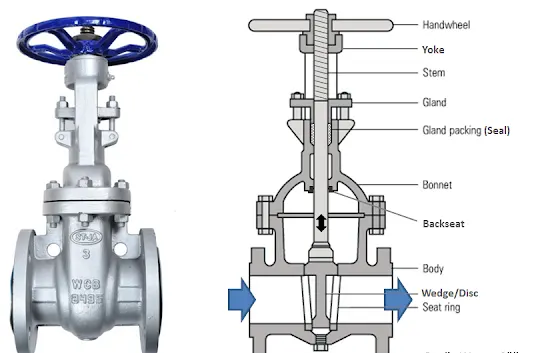
figure no.1.
Gate valve Construction:
Common gate valves are actuated by a threaded stem that connects the actuator (e.g. handwheel or motor) to the gate. They are characterised as having either a rising or a nonrising stem, depending on which end of the stem is threaded. Rising stems are fixed to the gate and rise and lower together as the valve is operated, providing a visual indication of valve position. The actuator is attached to a nut that is rotated around the threaded stem to move it. Nonrising stem valves are fixed to, and rotate with, the actuator, and are threaded into the gate. They may have a pointer threaded onto the stem to indicate valve position, since the gate's motion is concealed inside the valve. Nonrising stems are used where vertical space is limited.
Please refer the below photo and animation of the Gate valve.
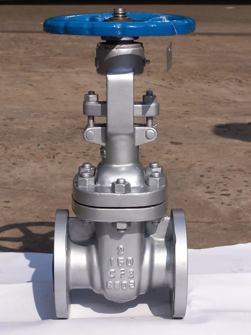
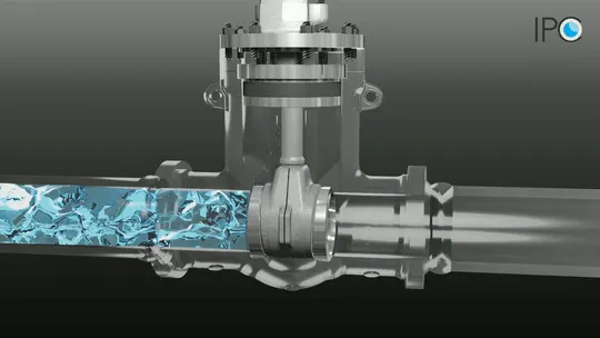
Valve Bonnet: The cover for the opening in the valve body is the bonnet. In some designs, the body itself is split into two sections that bolt together. Like valve bodies, bonnets vary in design. Some bonnets function simply as valve covers, while others support valve internals and accessories such as the stem, disk, and actuator.
Valve Trim: The internal elements of a valve are collectively referred to as a valve's trim. The trim typically includes a disk, seat, stem, and sleeves needed to guide the stem. A valve's performance is determined by the disk and seat interface and the relation of the disk position to the seat.
Disk and Seat: For a valve having a bonnet, the disk is the third primary principal pressure boundary. The seat or seal rings provide the seating surface for the disk. In some designs, the body is machined to serve as the seating surface and seal rings are not used.
Stem: The stem, which connects the actuator and disk, is responsible for positioning the disk. Stems are typically forged and connected to the disk by threaded or welded joints.
Valve Actuator: The actuator operates the stem and disk assembly. An actuator may be a manually operated hand wheel, manual lever, motor operator, solenoid operator, pneumatic operator, or hydraulic ram.
Valve Packing: Most valves use some form of packing to prevent leakage from the space between the stem and the bonnet. Packing is commonly a fibrous material (such as flax) or another compound (such as Teflon) that forms a seal between the internal parts of a valve and the outside where the stem extends through the body.
Classification of Gate Valve
Gate valves perform an on/off function accomplished by means of a flow-controlling gate centered in the valve body
between the inlet and outlet sides of the valve.
The various types of Gate Valves are as follows:
i) Ball Valves
ii) Plug Valves
iii) Butterfly Valves
iv) Needle Valves
v) Parallel Disk Valve
Flow coefficient:
The flow coefficient of a device is a relative measure of its efficiency at allowing fluid flow. It describes the relationship between the pressure drop across an orifice valve or other assembly and the corresponding flow rate.
Mathematically the flow coefficient Cv (or flow-capacity rating of valve) can be expressed as :
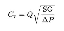
where:
- Q is the rate of flow (expressed in US gallons per minute),
- SG is the specific gravity of the fluid (for water = 1).
- ΔP is the pressure drop across the valve (expressed in psi).
Flow factor:
The metric equivalent flow factor (Kv) is calculated using metric units :
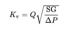
where
- Kv is the flow factor (expressed in m3·h−1).
- Q is the flowrate (expressed in cubic metres per hour m3·h−1),
- SG is the specific gravity of the fluid (for water = 1),
- ∆P is the differential pressure across the device (expressed in bar).
Kv can be calculated from Cv using the equation:
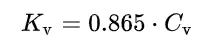
or
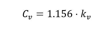
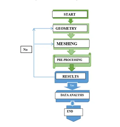
Please refer the below chart for the CFD work flow parametric study on the gate valve simulation.
Geometry Set-up:
Please refer the below photo for the Geometry given.
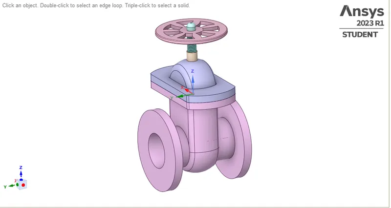
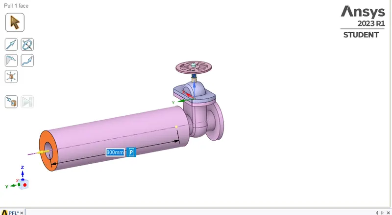
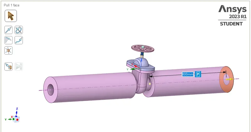
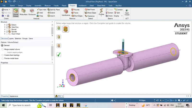
Extend the both right and left face 800 mm by pull comand as shown below photo.
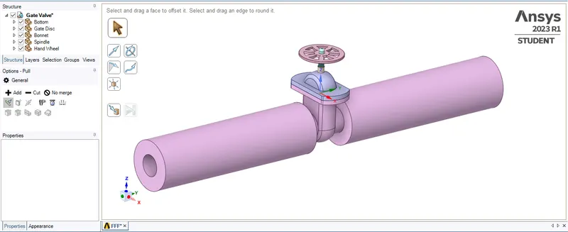
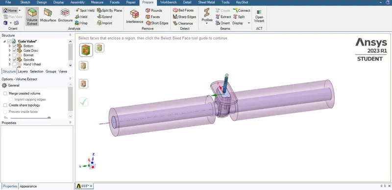
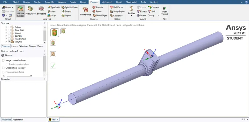
Volume extract in prepare comand and ensure that keep the bottom, Gate Disc and spindel in view only as shown below photo.
Parameterizing the Lift:
For the parametric study, the input parameter that needs to be parameterized is the lift of the Gate Disc.
For this use the move feature and select the Gate Disc body and move it along the positive Z direction.
You will asked to enter a value beside which a "P" button can be seen click the same.
Now the fluid region need to get updated for the change in geometry which can be done by the update volume body in context option.
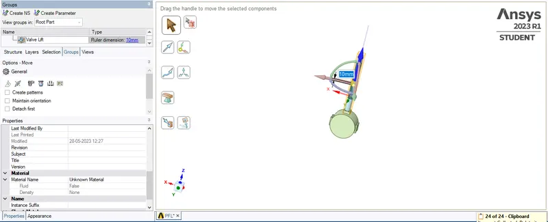
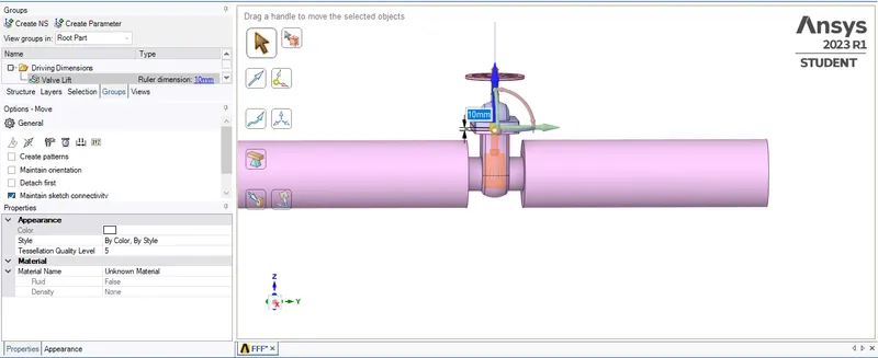
Path: Sketch>Move> Select component> Select the spendle, In the properties select the group as shown below photo.

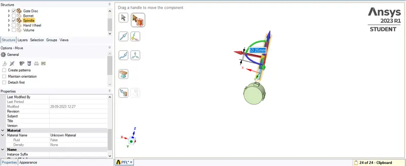
In the groups click on Create parameter> Under Name> Valve Lift> give 10 mm as shoen below photo.
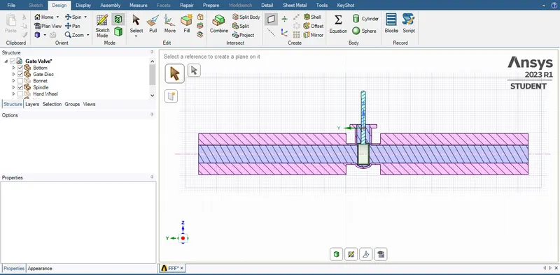
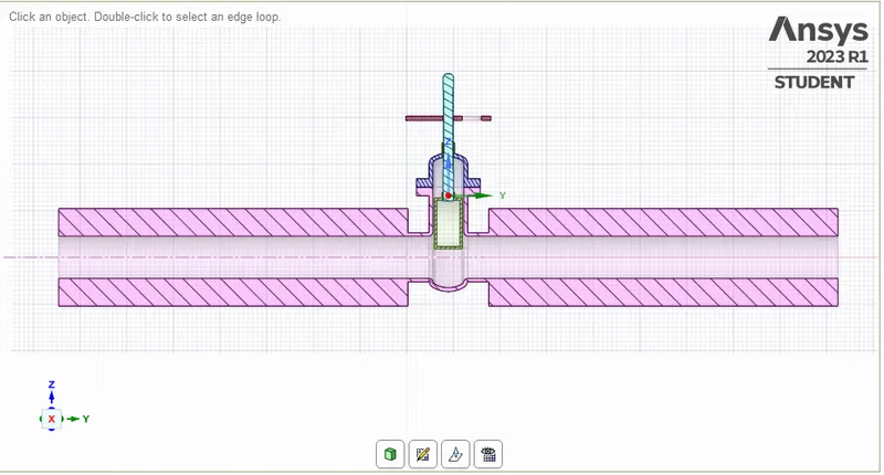
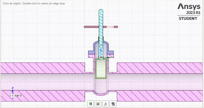
Please refer the below photo for the Cut section of the ZY plane.
Meshing Set-up:
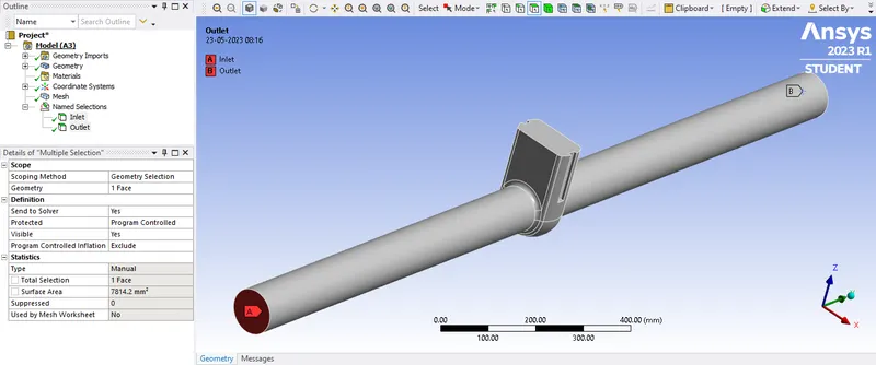
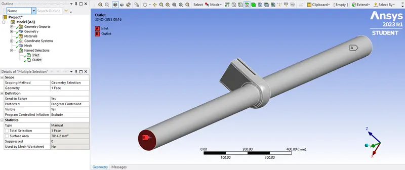
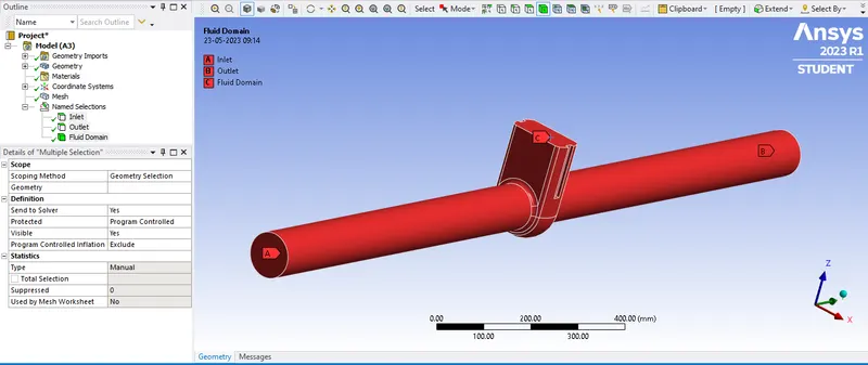
Nomenclature of the Extracted volume Inlet, Outlet and Fluid Domain as shown below photo
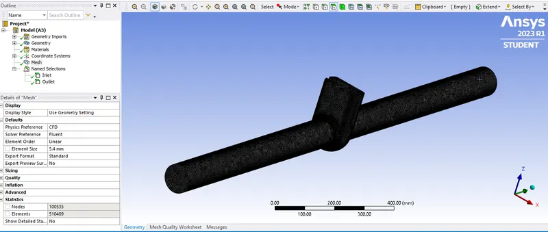
I have applied the element size of 5.4 mm and obtained Elements of 510409 and Nodes of 100535 as shown in the below photo.
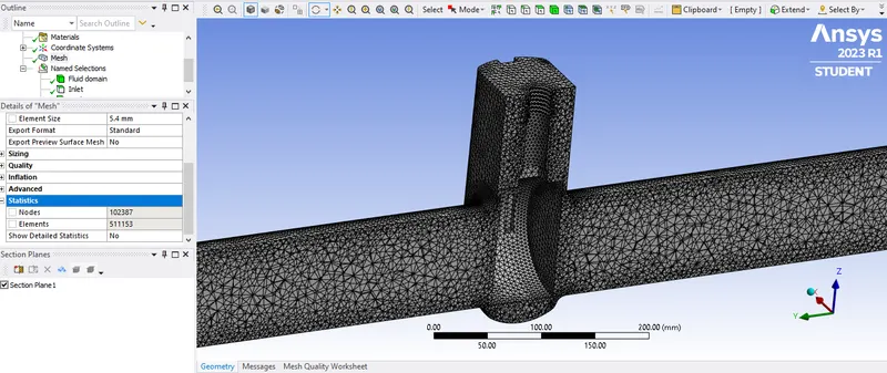
Cut section view of the meshed Extracted fluid volume as shown below photo.
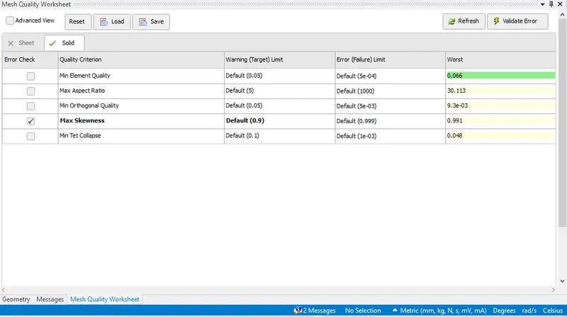
Please refer the below photo for the Mesh Quality Worksheet obtained.
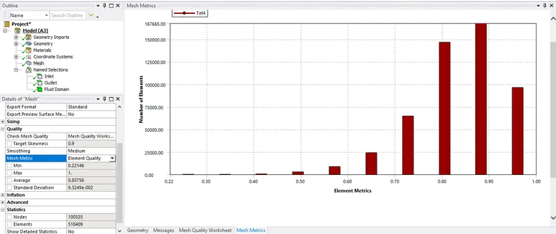
Please refer the below photo for the Element Quality and the average value 0.83756 obtained
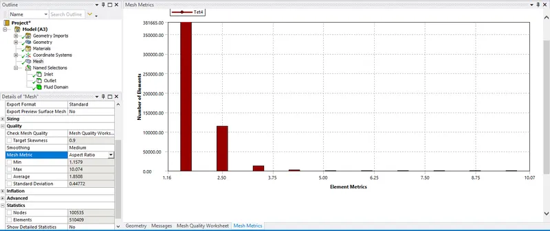
Please refer the below photo for the Aspect ratio and the average value 1.8508 obtained
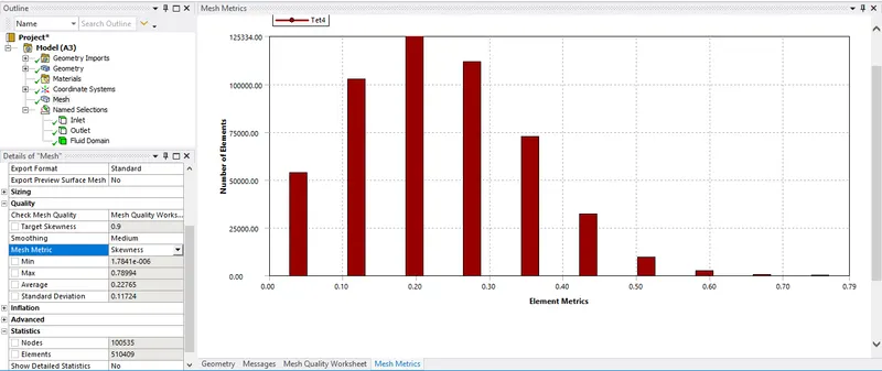
Please refer the below photo for the Skewness and the average value 0.22765 obtained
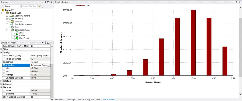
Please refer the below photo for the Ortogonal Quality and the average value 0.77063 obtained
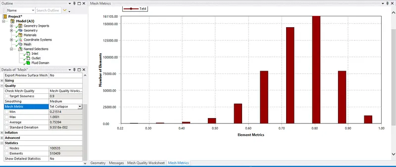
Please refer the below photo for the Tet Collapse and the average value 0.75394 obtained
Fluent setup:
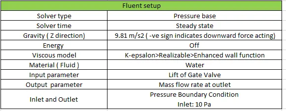
Please refer the below table for the Fluent setup applied.
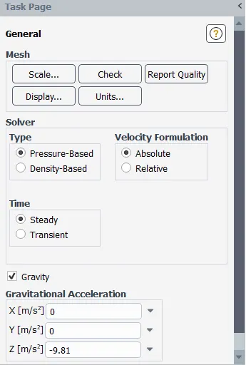
Please refer the below photo for the Solver type, Solver time, Gravity applied.
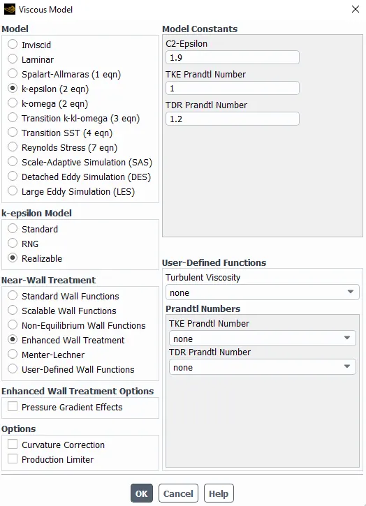
Please refer the below photo for the viscous model applied.
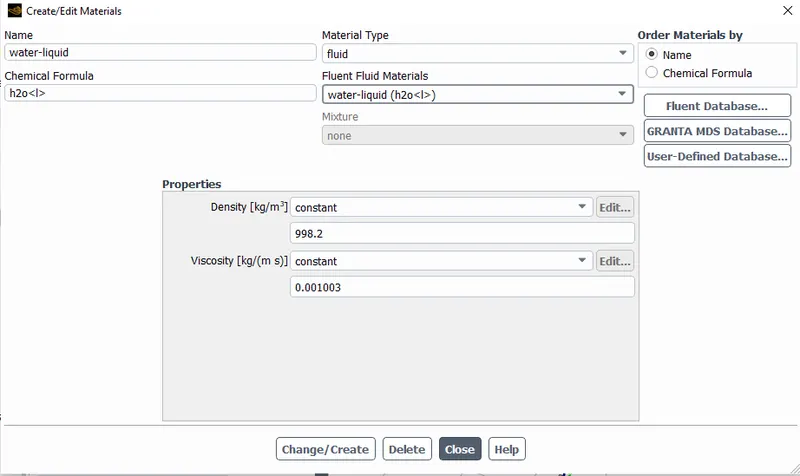
Please refer the below photo for the material applied.
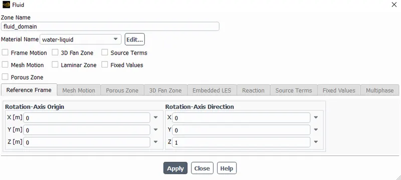
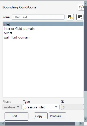
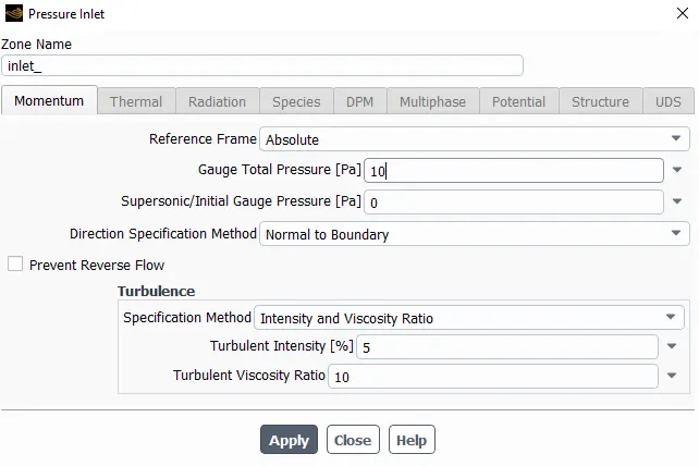
Please refer the below photo for the Inlet boundary conditions, pressure inlet 10 Pa applied.
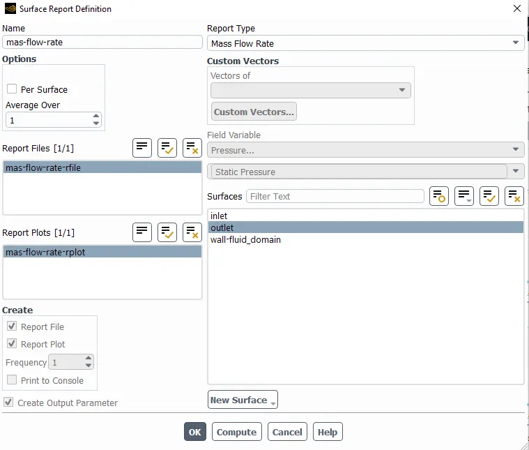
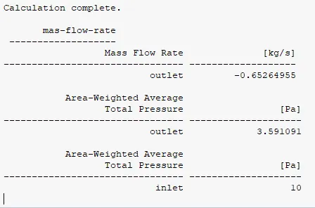
Report defination for the Mass flow rate at the outlet as shown below photo.
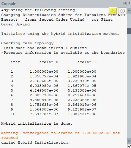
Please refer the below photo for the Initialization done.
After initialization I have run calculation for 500 iterations.
Results:
Please refer the below photo for the parametric table obtained.
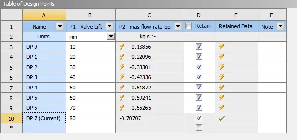
1) DP 0 Case:
Please refer the below photo for the geometry cut section obtained for 10% or 10 mm Valve lift.
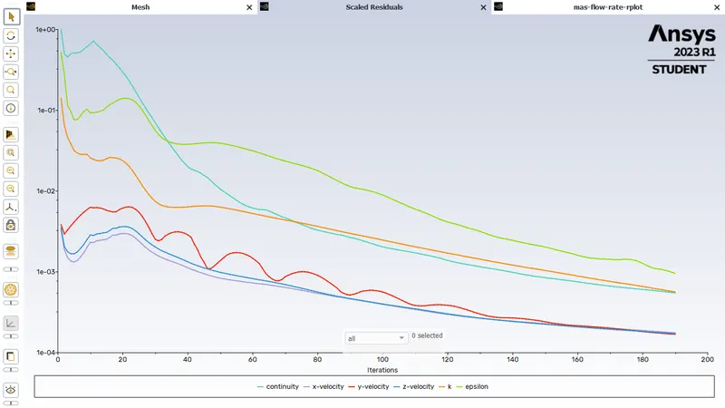
Please refer the below photo for the Residuals obtained.
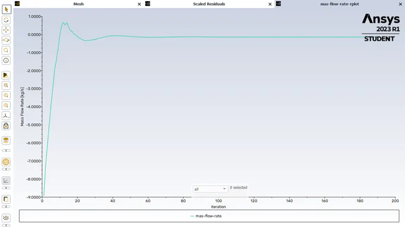
Please refer the below photo for the Mass flow rate plot obtained.
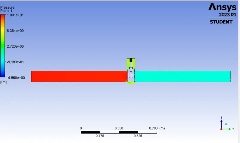
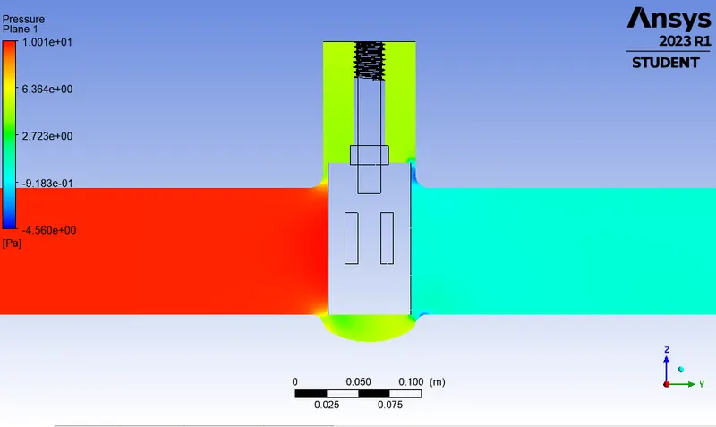
Please refer the below photo for the Pressure plot obtained.
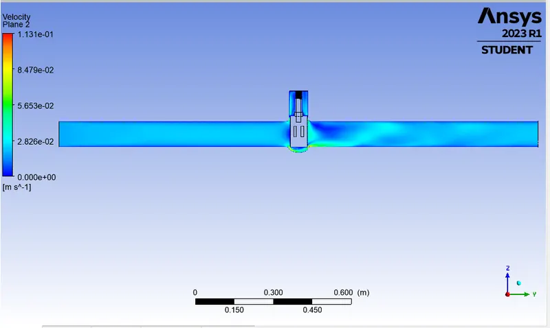
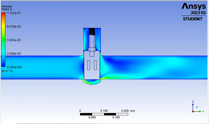
Please refer the below photo for the velocity plot obtained.
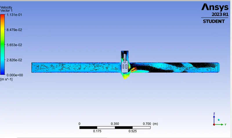
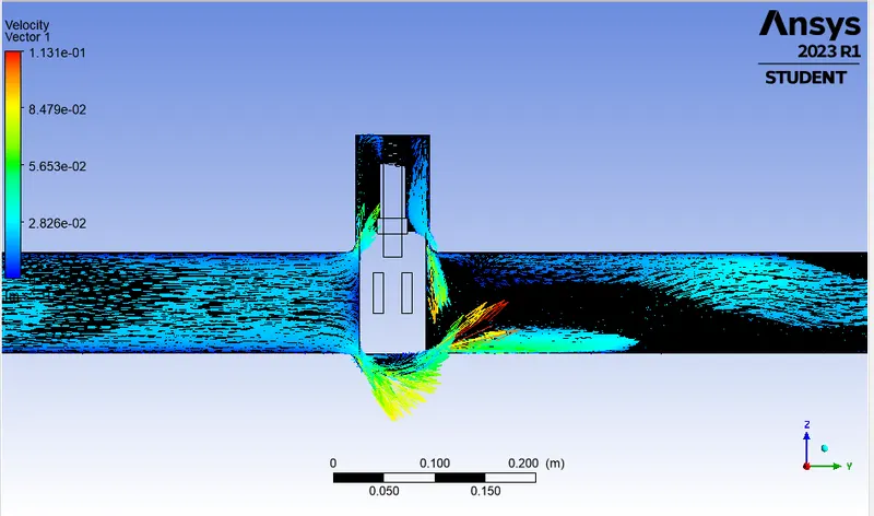
Please refer the below photo for the Velocity vector plot obtained.
Please refer the below photo for the Streamline plot obtained.
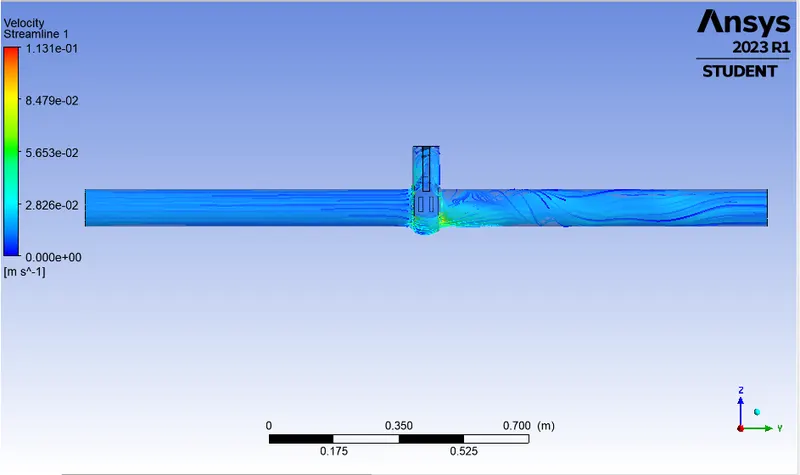
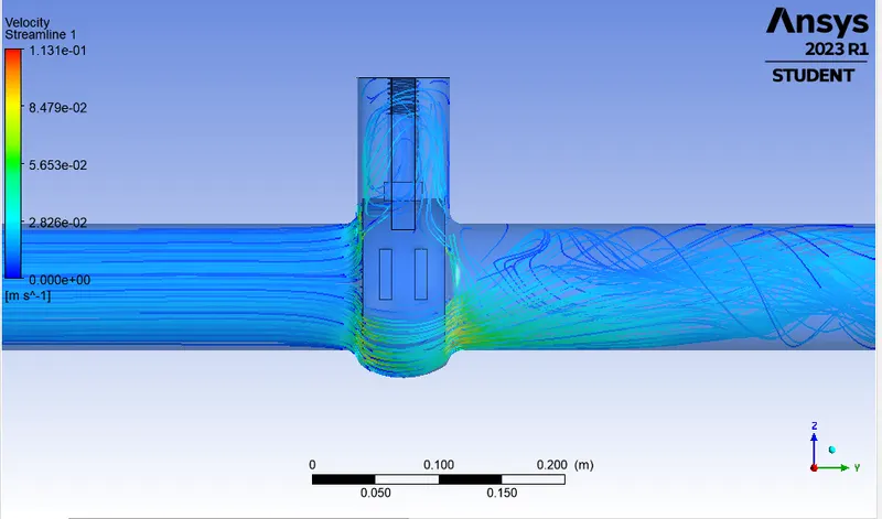
Please refer the below photo for the Animation of the model obtained.
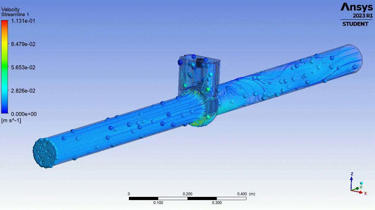
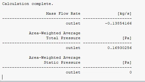
Please refer the below photo for the Results obtained.
2) DP 1 Case:
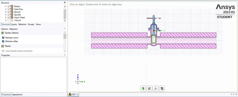
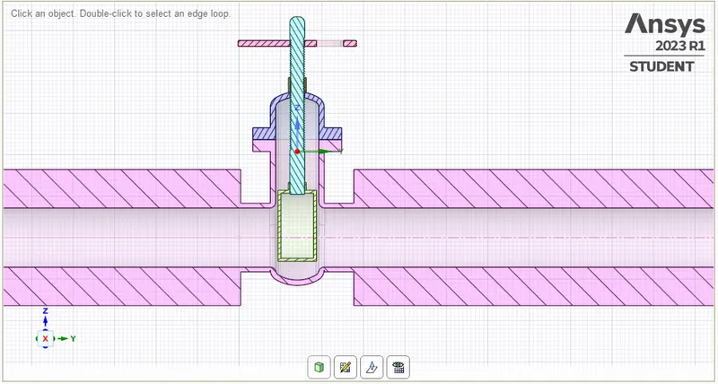
Please refer the below photo for the geometry cut section obtained for 20% or 20 mm Valve lift.
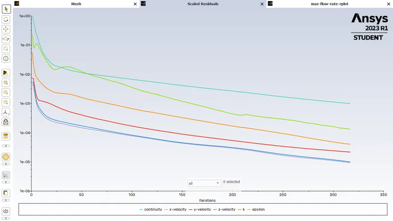
Please refer the below photo for the Residuals obtained.
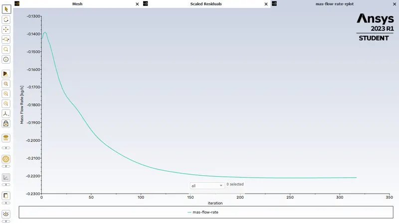
Please refer the below photo for the Mass flow rate plot obtained.
Please refer the below photo for the Pressure plot obtained.
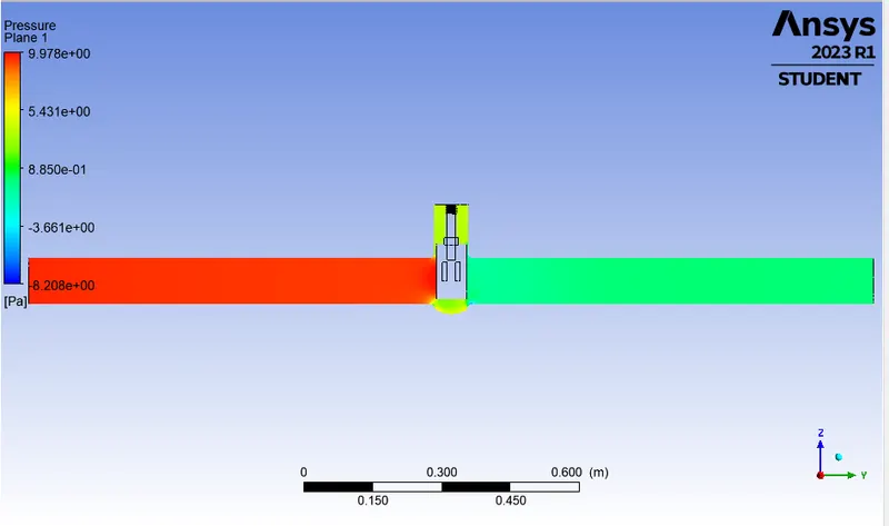
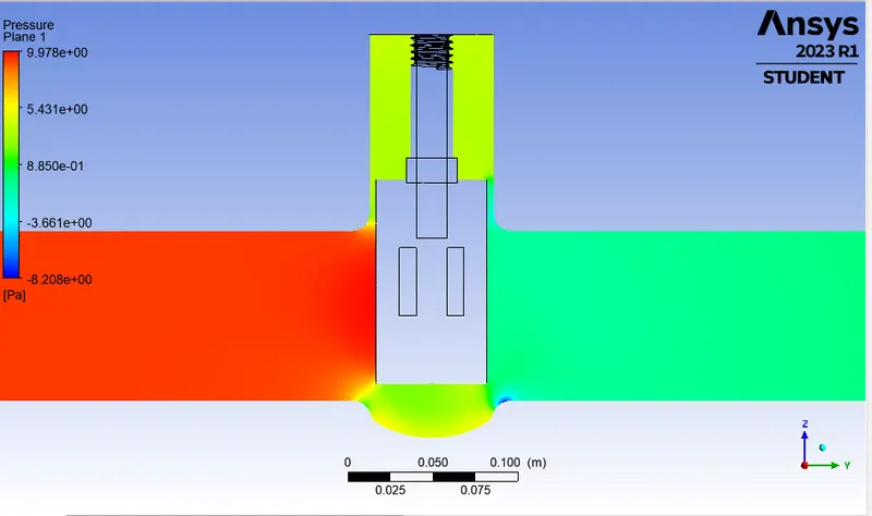
Please refer the below photo for the velocity plot obtained.
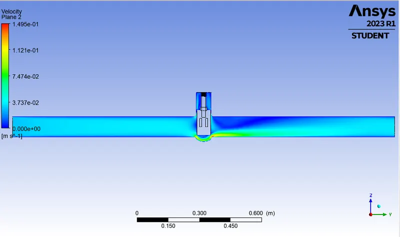
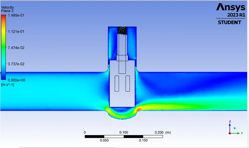
Please refer the below photo for the Velocity vector plot obtained.
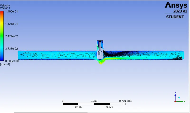
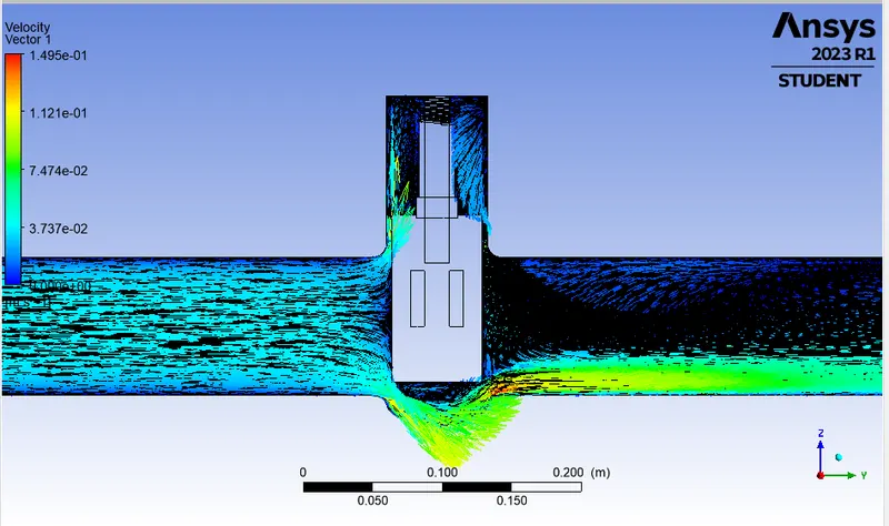
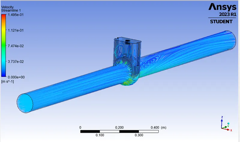
Please refer the below photo for the Streamline plot obtained.
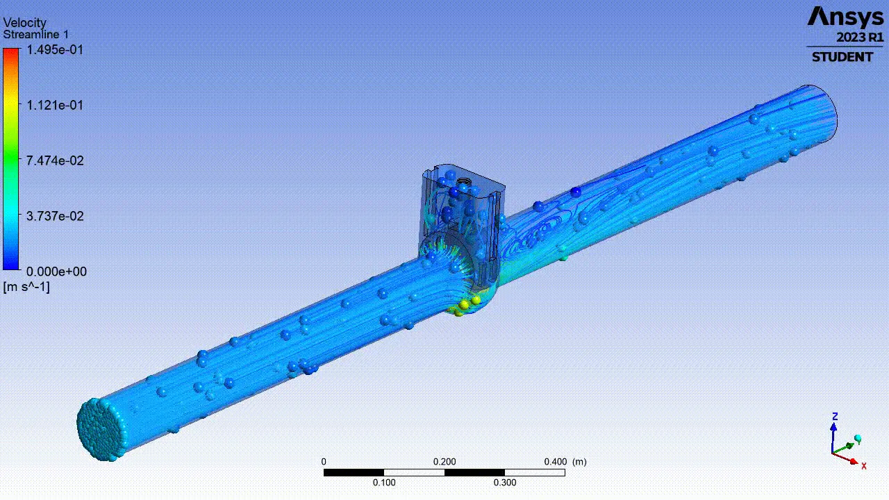
Please refer the below photo for the Animation of the model obtained.
Please refer the below photo for the Results obtained.
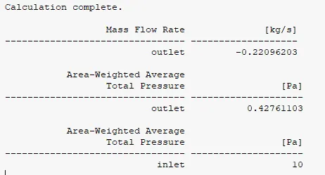
3) DP 2 Case:
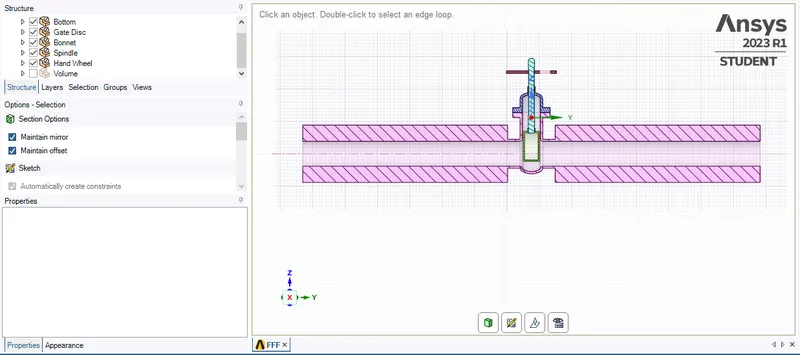
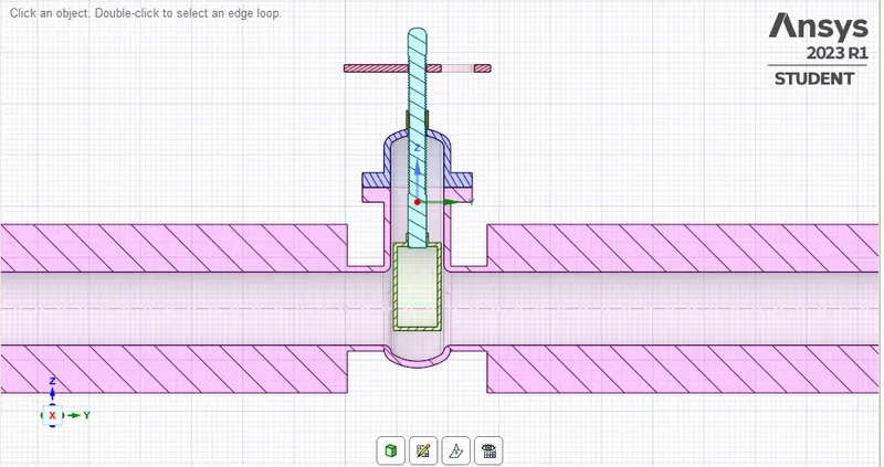
Please refer the below photo for the geometry cut section obtained for 30% or 30 mm Valve lift.
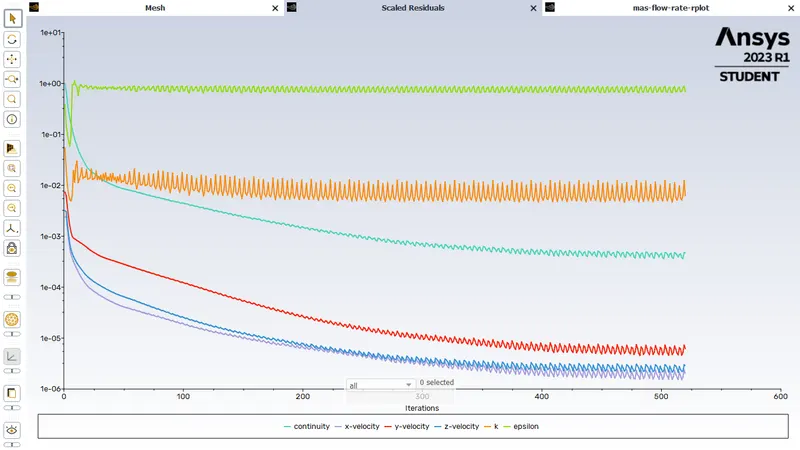
Please refer the below photo for the Residuals obtained.
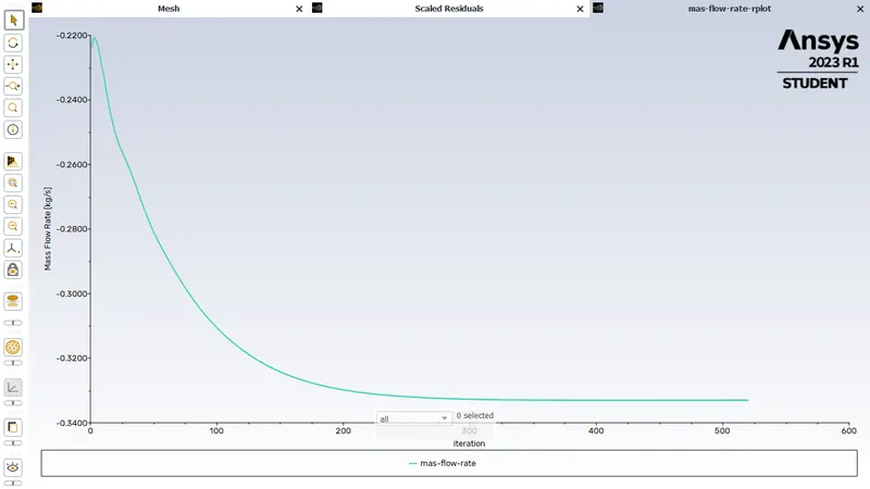
Please refer the below photo for the Mass flow rate plot obtained.
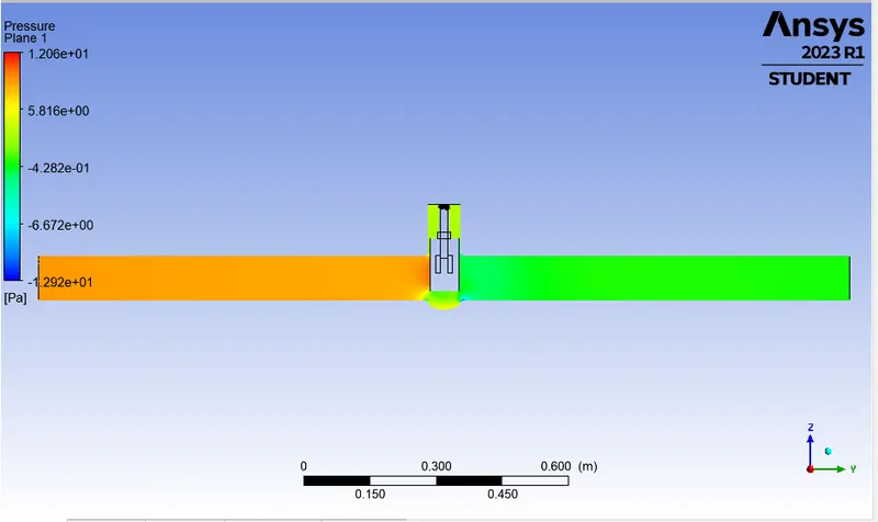
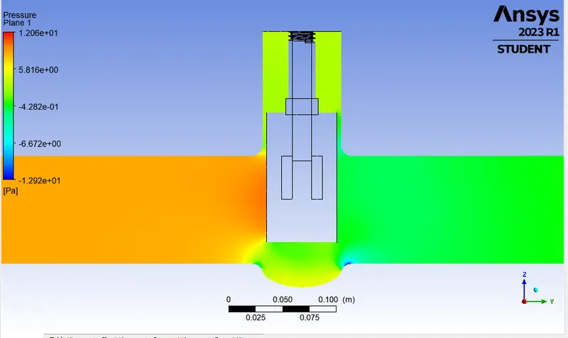
Please refer the below photo for the Pressure plot obtained.
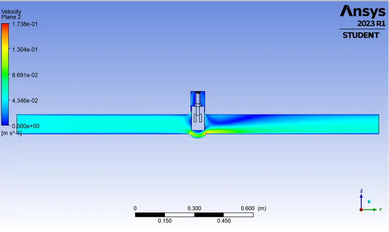
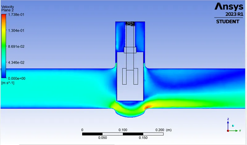
Please refer the below photo for the velocity plot obtained.
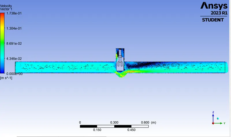
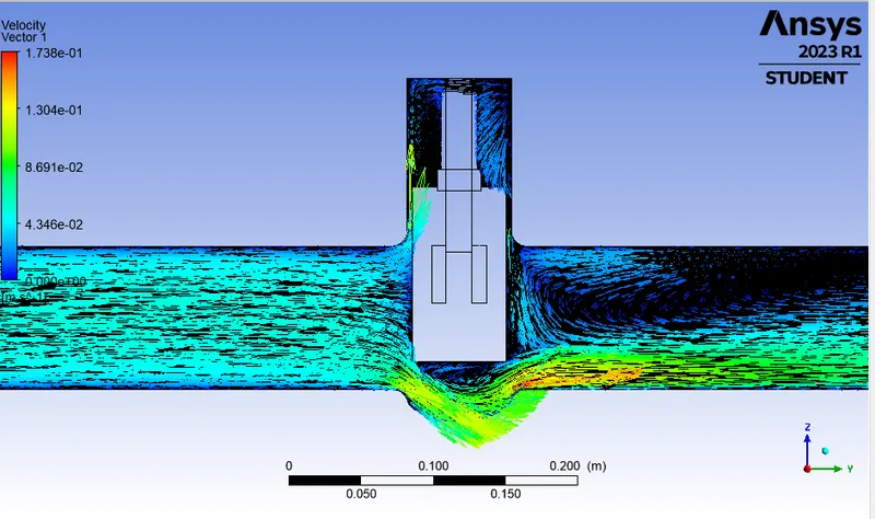
Please refer the below photo for the Velocity vector plot obtained.
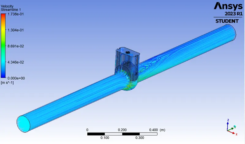
Please refer the below photo for the Streamline plot obtained.
Please refer the below photo for the Animation of the model obtained.
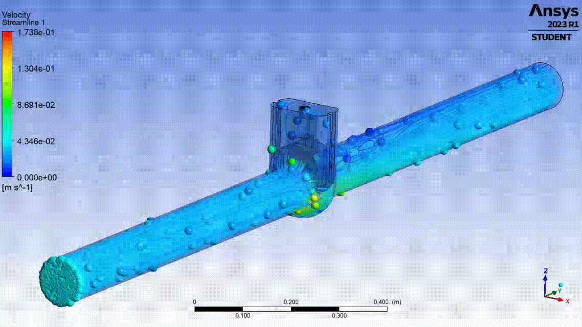
Please refer the below photo for the Results obtained.
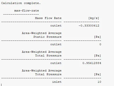
4) DP 3 Case:
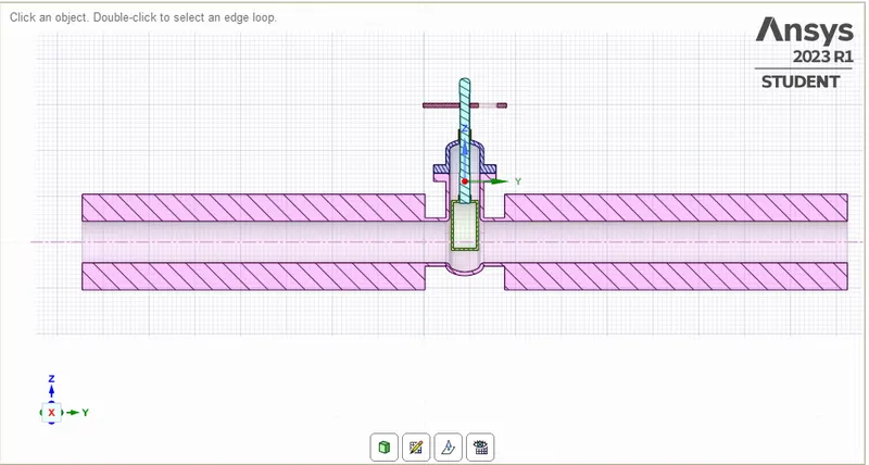
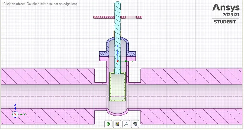
Please refer the below photo for the geometry cut section obtained for 40% or 40 mm Valve lift.
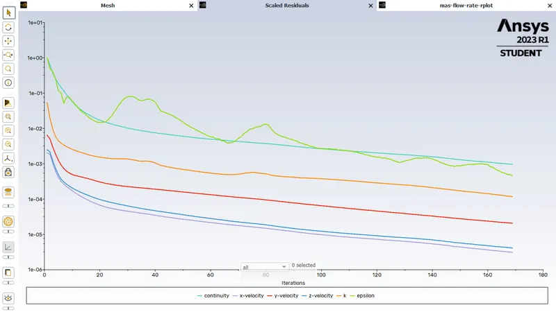
Please refer the below photo for the Residuals obtained.
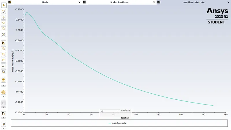
Please refer the below photo for the Mass flow rate plot obtained.
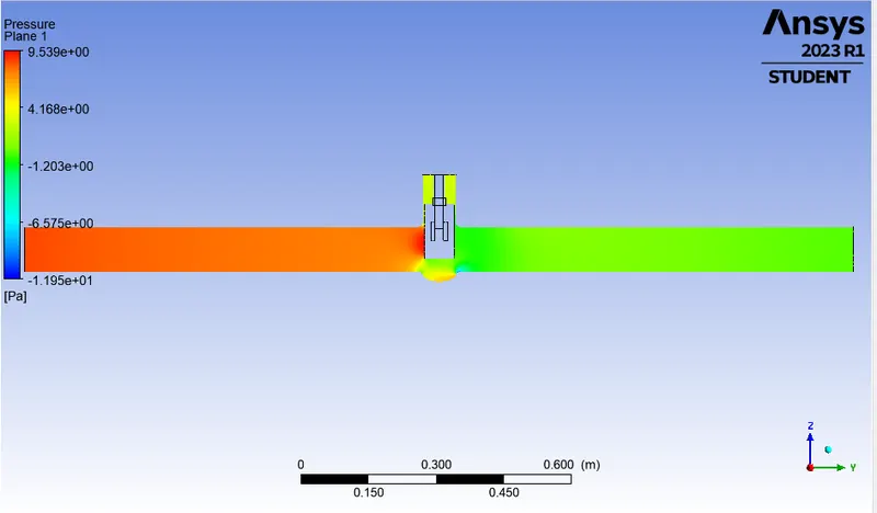
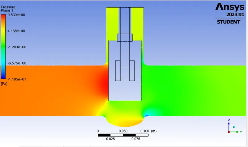
Please refer the below photo for the Pressure plot obtained.
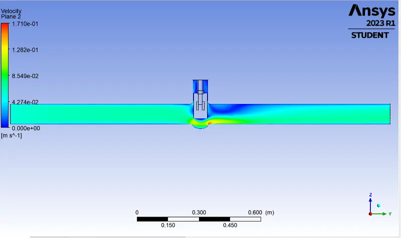
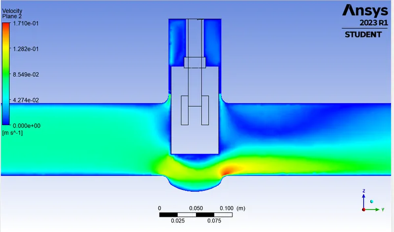
Please refer the below photo for the velocity plot obtained.
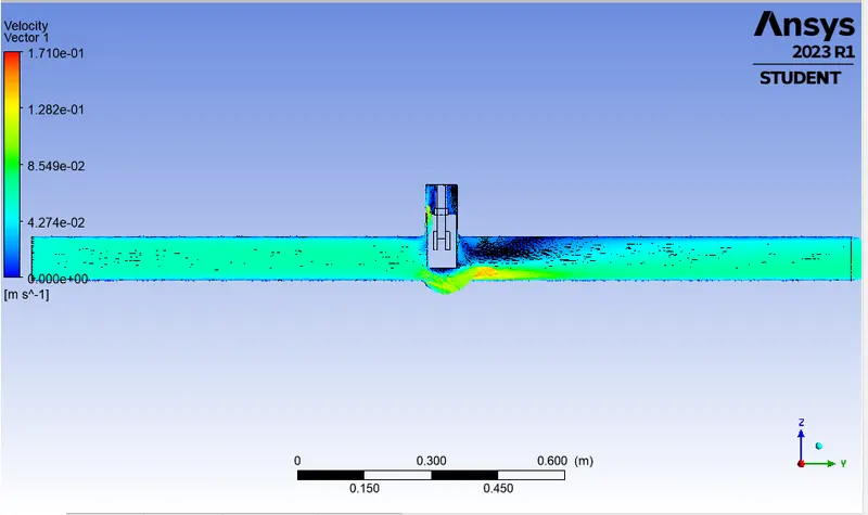
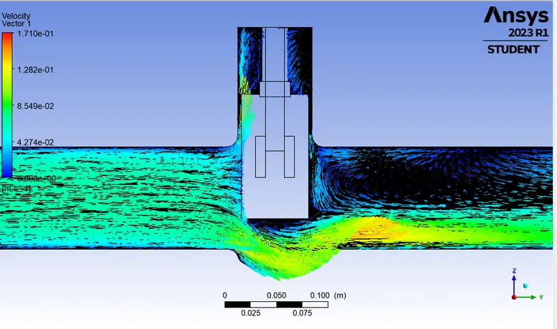
Please refer the below photo for the Velocity vector plot obtained.
Please refer the below photo for the Streamline plot obtained.
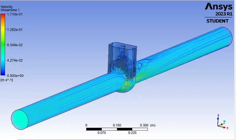
Please refer the below photo for the Animation of the model obtained.
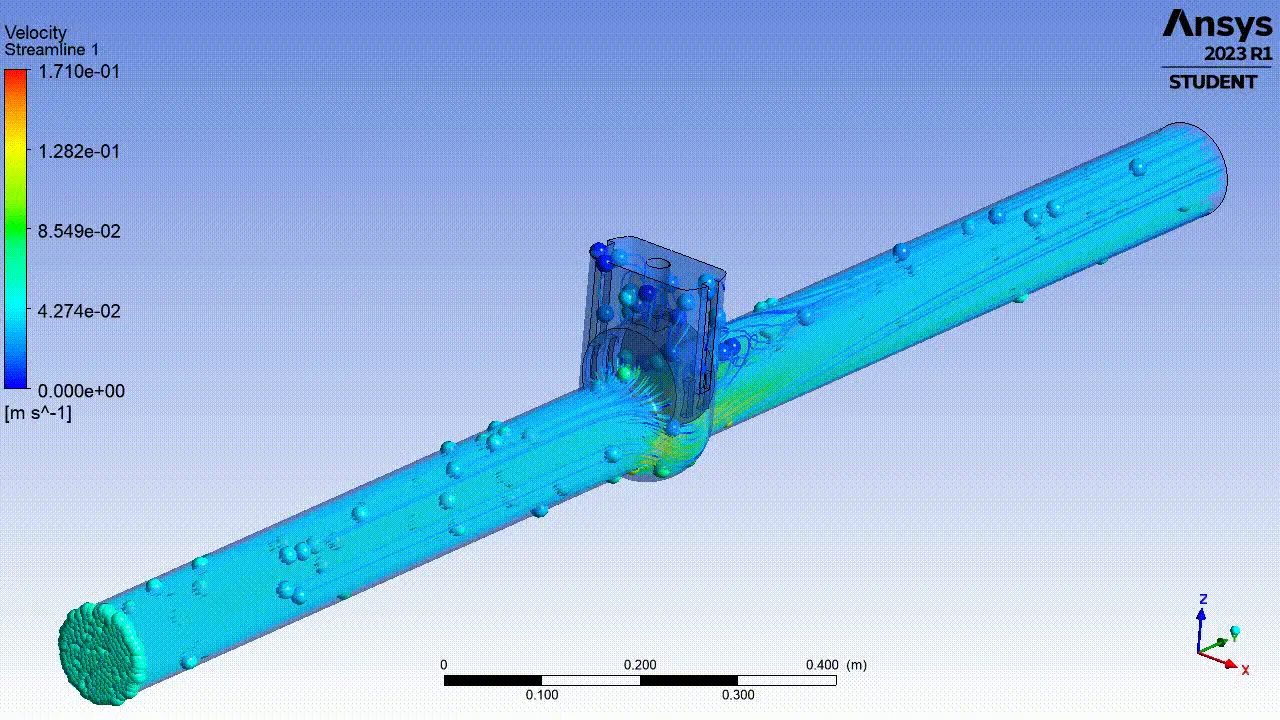
Please refer the below photo for the Results obtained.
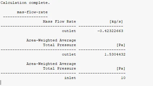
5) DP 4 Case:
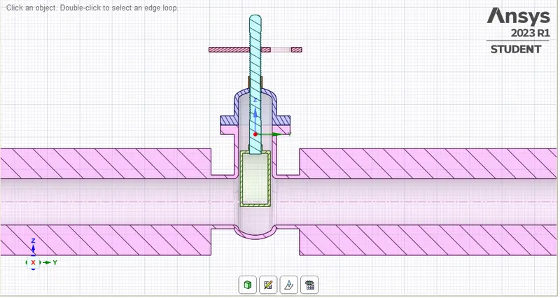
Please refer the below photo for the geometry cut section obtained for 50% or 50 mm Valve lift.
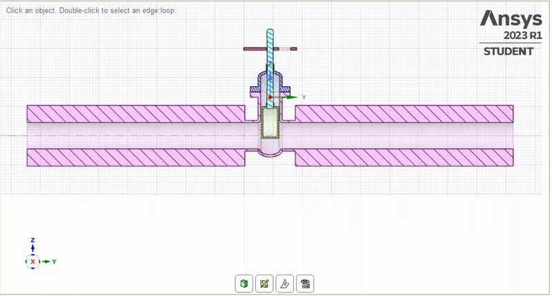
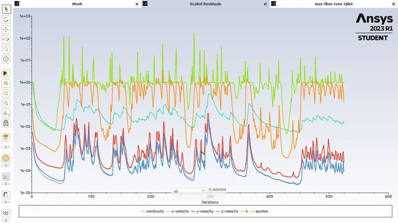
Please refer the below photo for the Residuals obtained.
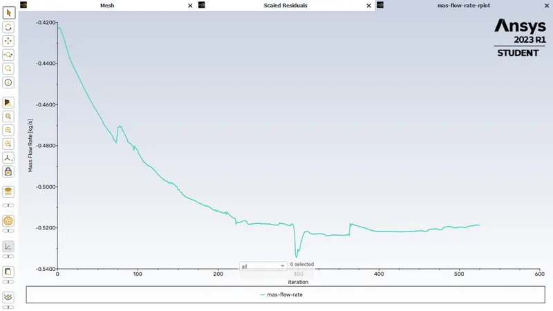
Please refer the below photo for the Mass flow rate plot obtained.
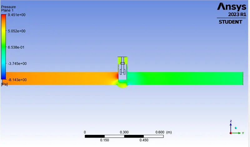
Please refer the below photo for the Pressure plot obtained.
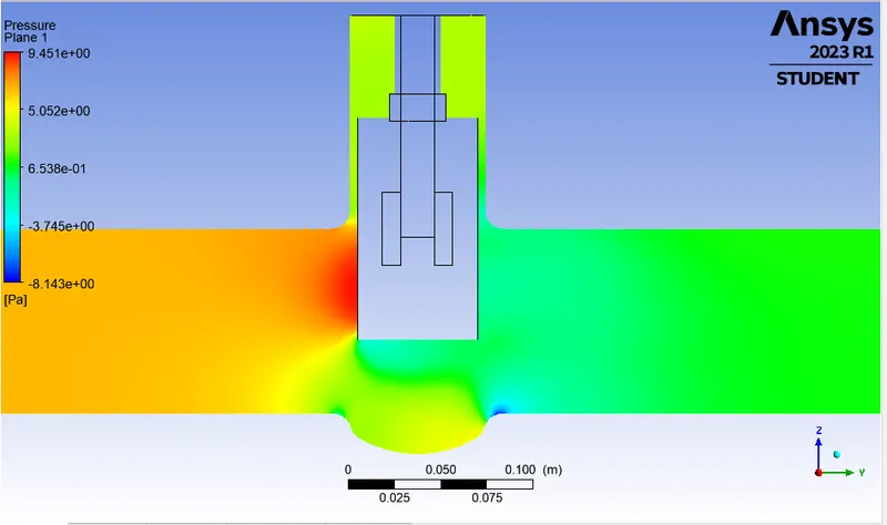
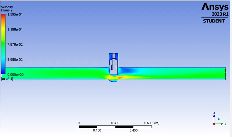
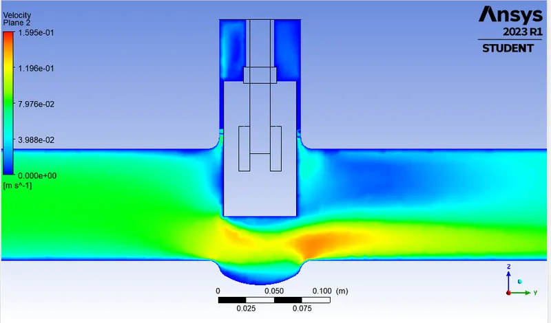
Please refer the below photo for the velocity plot obtained.
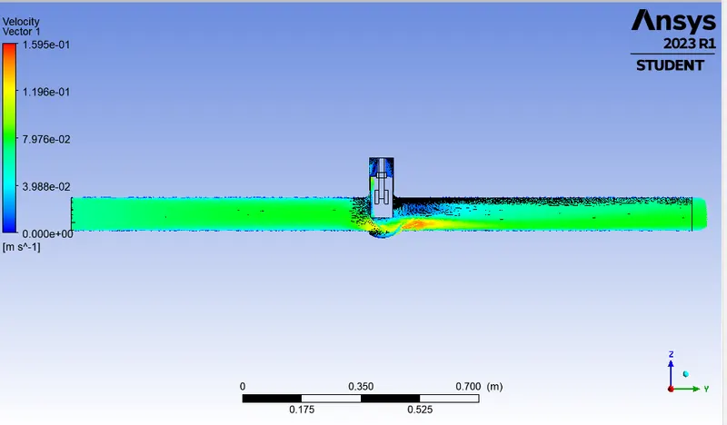
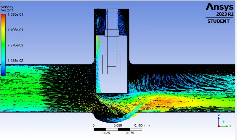
Please refer the below photo for the Velocity vector plot obtained.
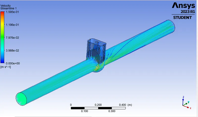
Please refer the below photo for the Streamline plot obtained.
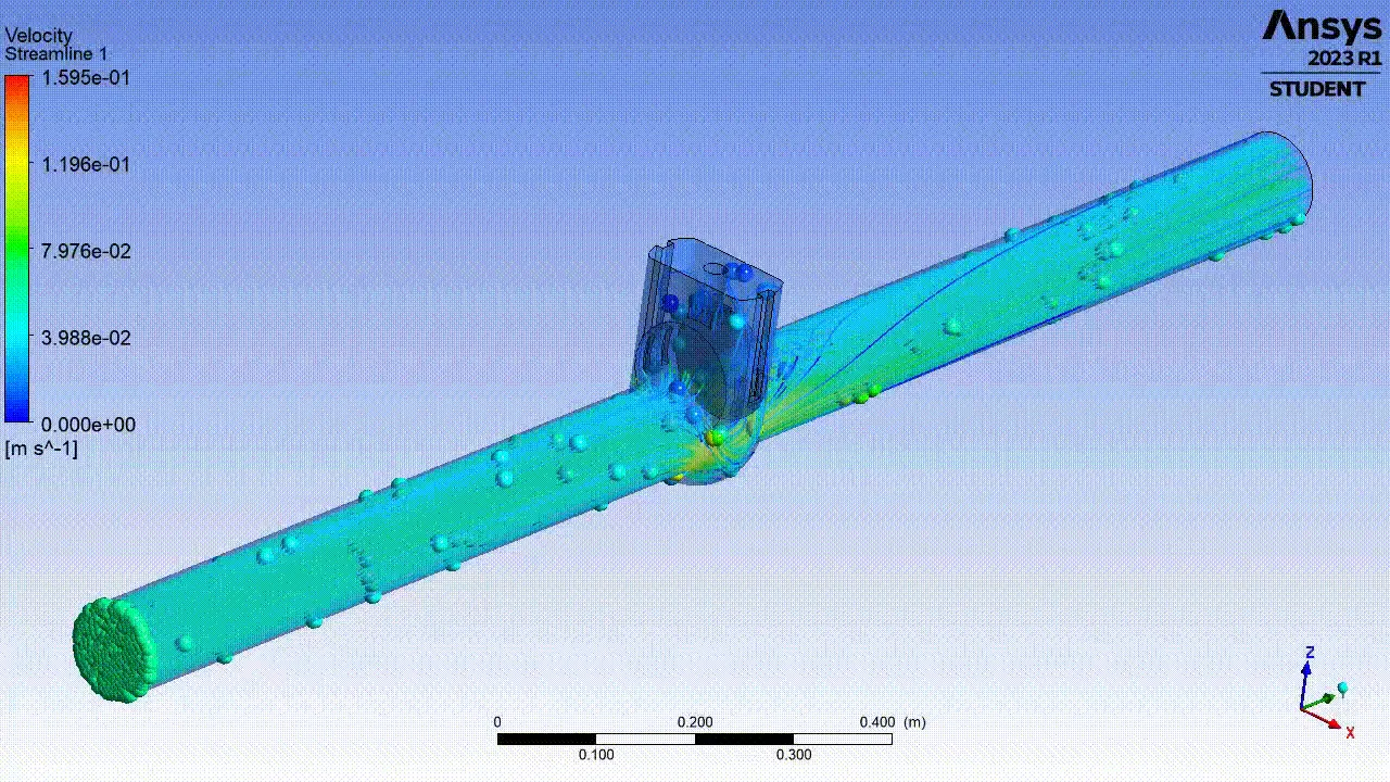
Please refer the below photo for the Animation of the model obtained.
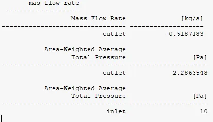
Please refer the below photo for the Results obtained.
6) DP 5 Case:
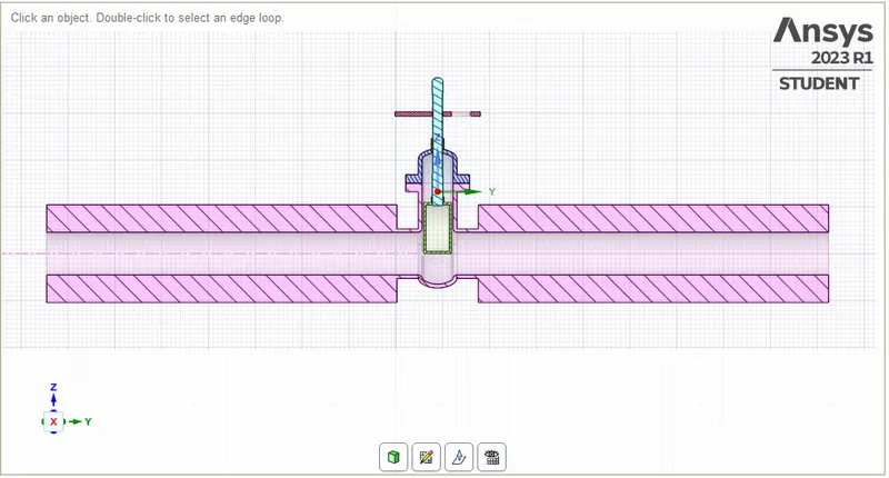
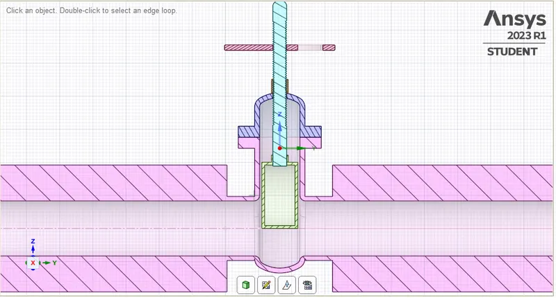
Please refer the below photo for the geometry cut section obtained for 60% or 60 mm Valve lift.
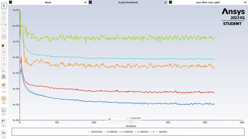
Please refer the below photo for the Residuals obtained.
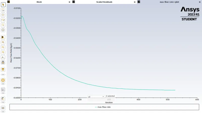
Please refer the below photo for the Mass flow rate plot obtained.
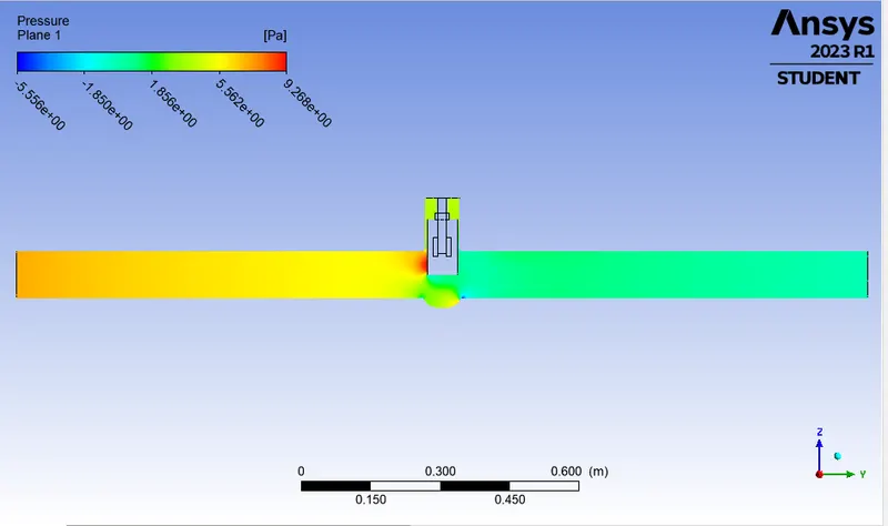
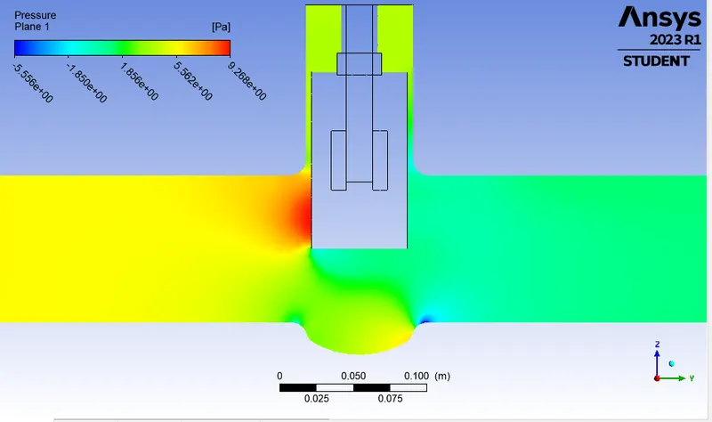
Please refer the below photo for the Pressure plot obtained.
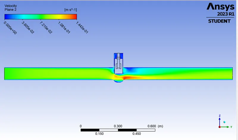
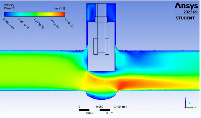
Please refer the below photo for the velocity plot obtained.
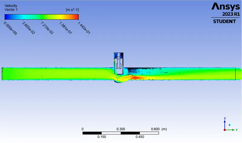
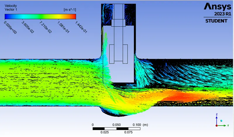
Please refer the below photo for the Velocity vector plot obtained.
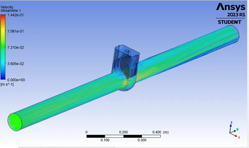
Please refer the below photo for the Streamline plot obtained.
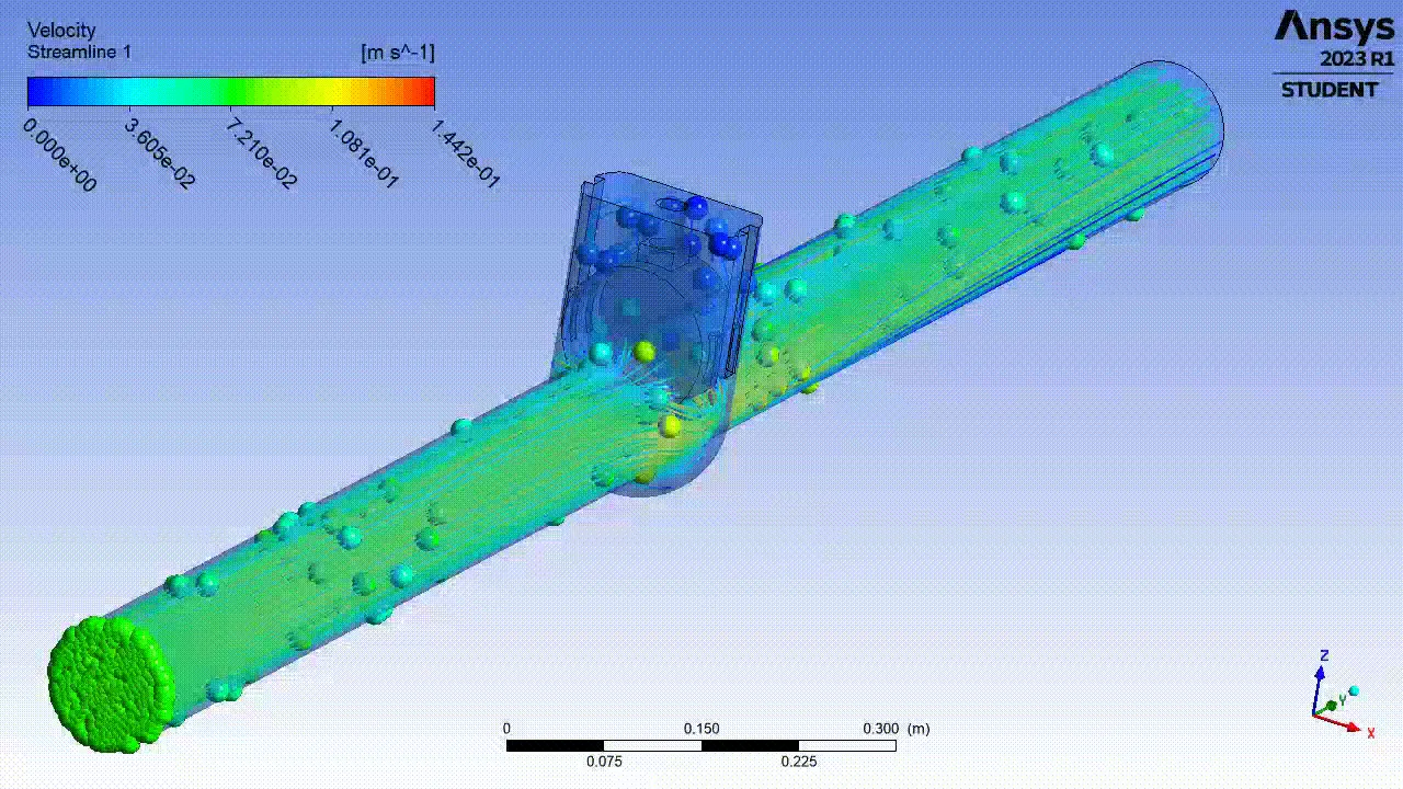
Please refer the below photo for the Animation of the model obtained.
Please refer the below photo for the Results obtained.
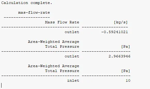
7) DP 6 Case:
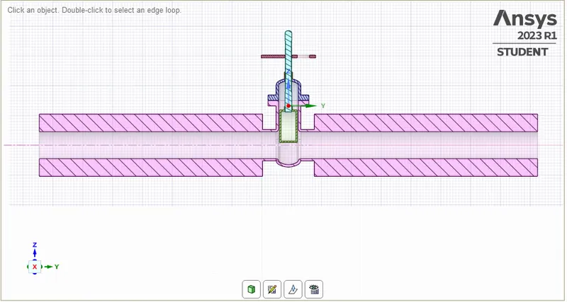
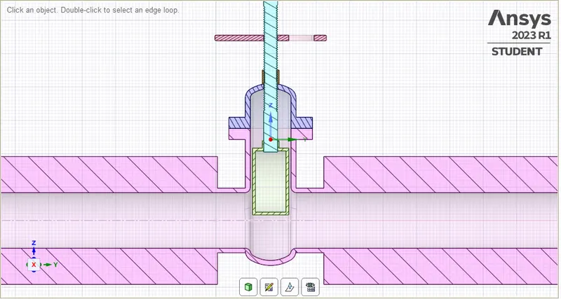
Please refer the below photo for the geometry cut section obtained for 70% or 70 mm Valve lift.
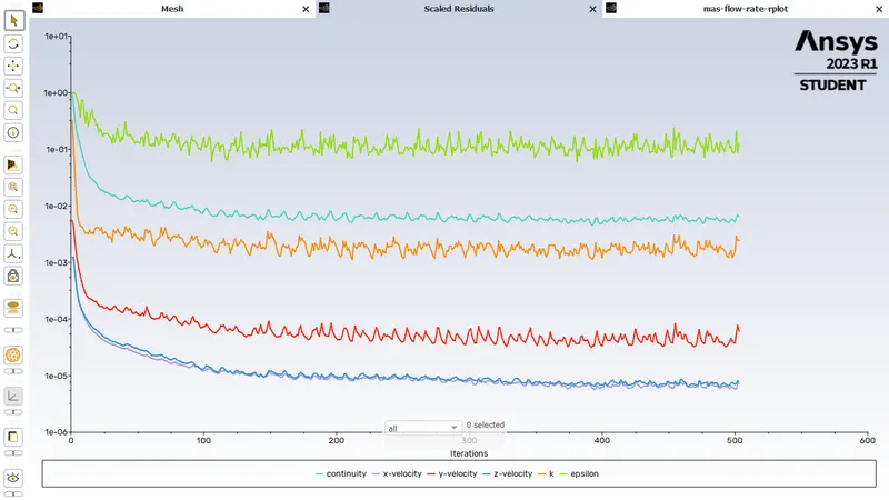
Please refer the below photo for the Residuals obtained.
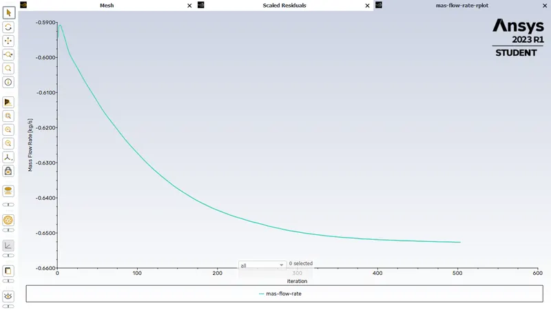
Please refer the below photo for the Mass flow rate plot obtained.
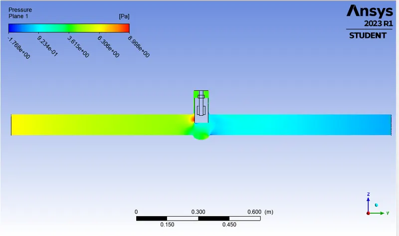
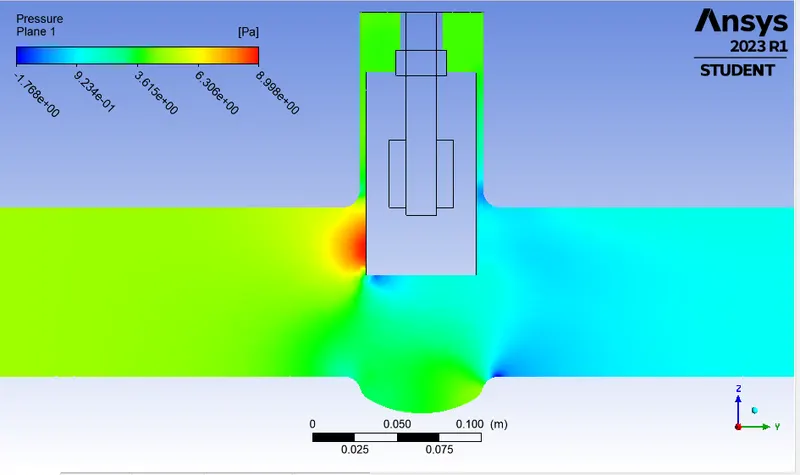
Please refer the below photo for the Pressure plot obtained.
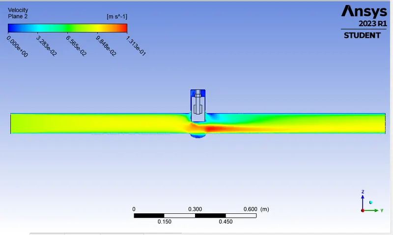
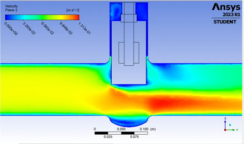
Please refer the below photo for the velocity plot obtained.
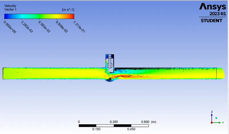
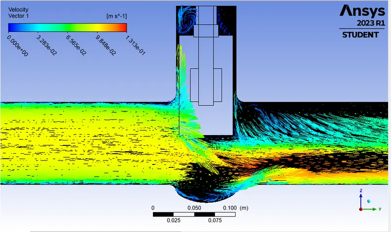
Please refer the below photo for the Velocity vector plot obtained.
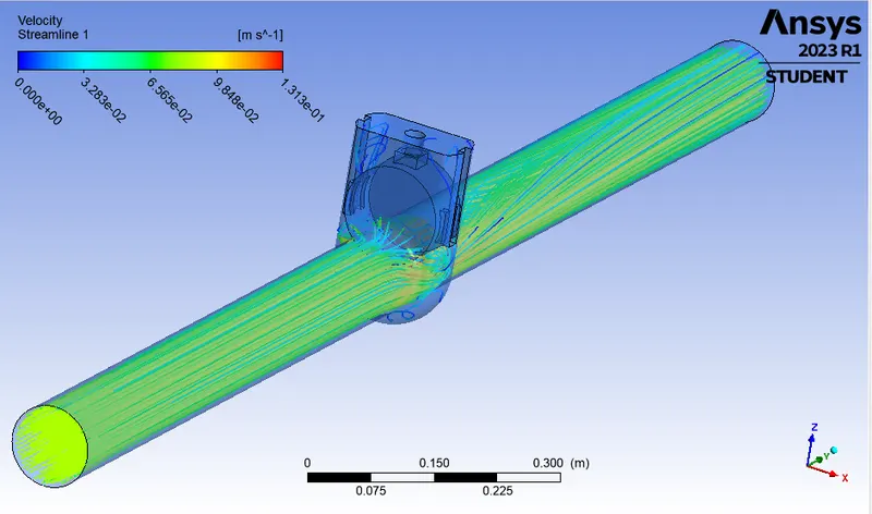
Please refer the below photo for the Streamline plot obtained.
Please refer the below photo for the Animation of the model obtained.
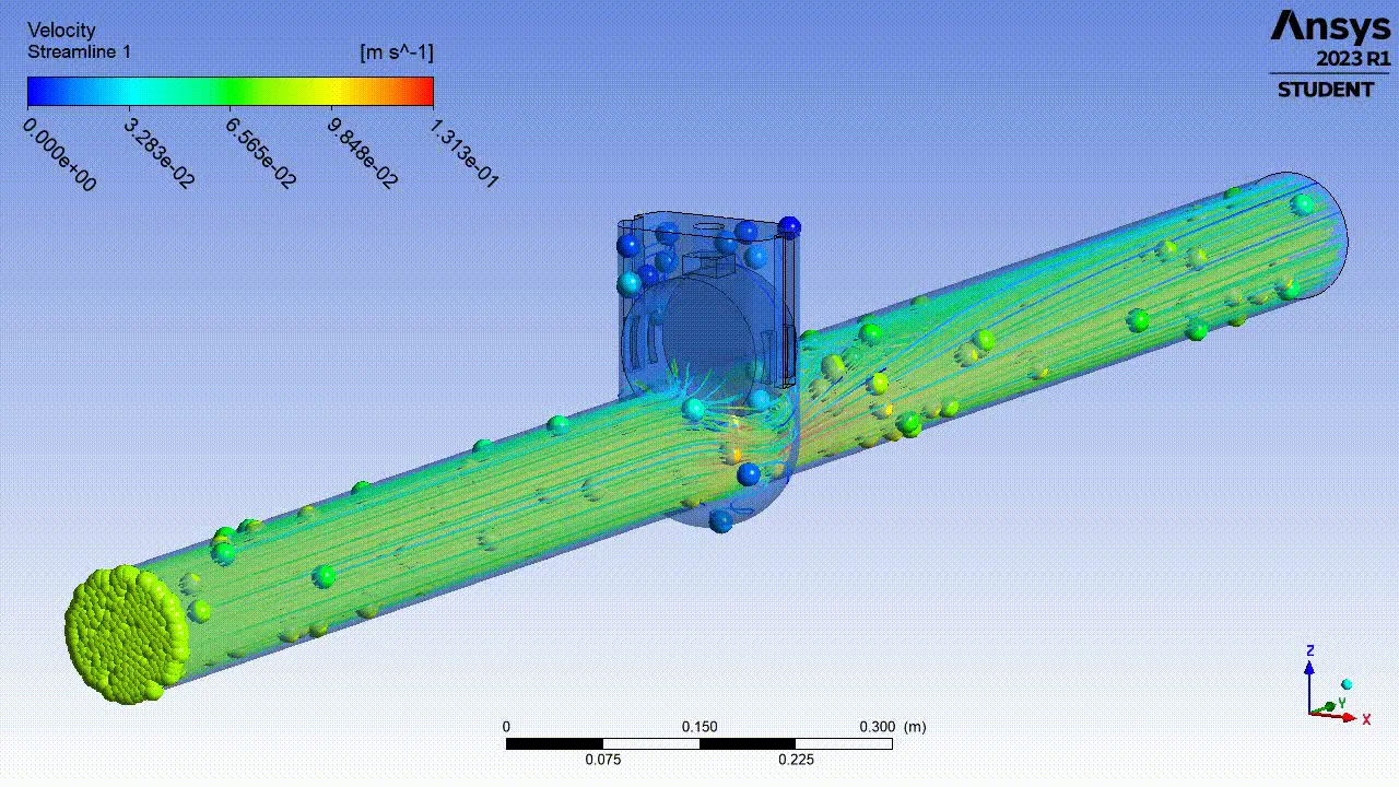
Please refer the below photo for the Results obtained.
8) DP 7 Case:
Please refer the below photo for the geometry cut section obtained for 80% or 80 mm Valve lift.
Please refer the below photo for the Residuals obtained.
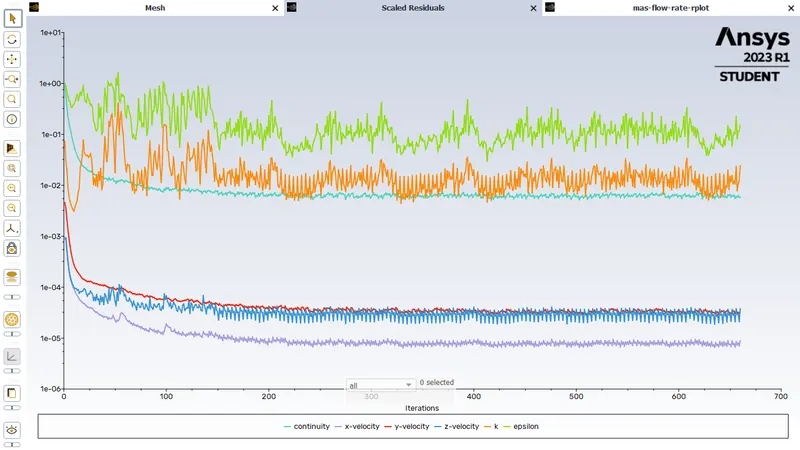
Please refer the below photo for the Mass flow rate plot obtained.
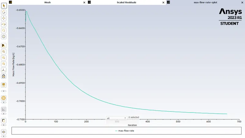
Please refer the below photo for the Pressure plot obtained.
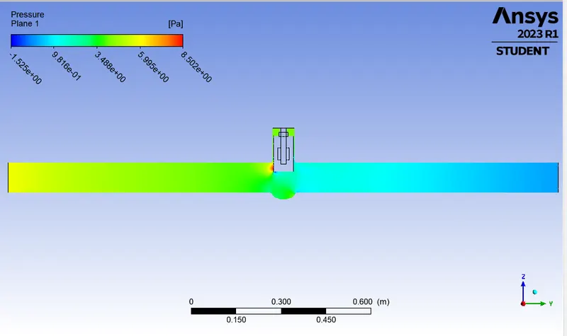
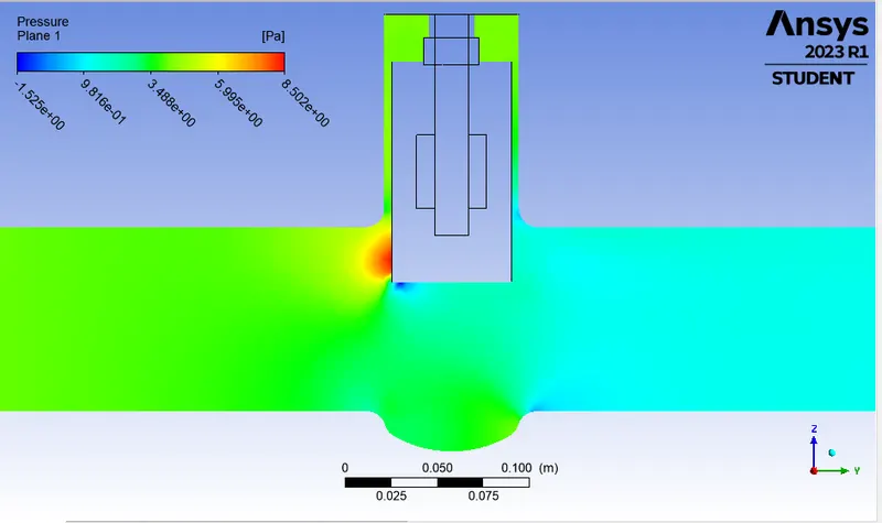
Please refer the below photo for the velocity plot obtained.
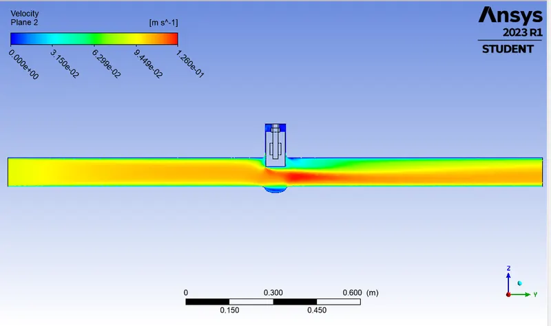
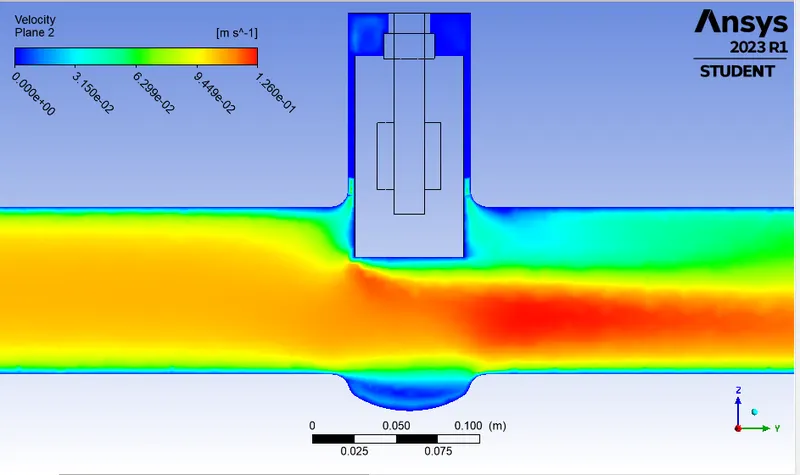
Please refer the below photo for the Velocity vector plot obtained.
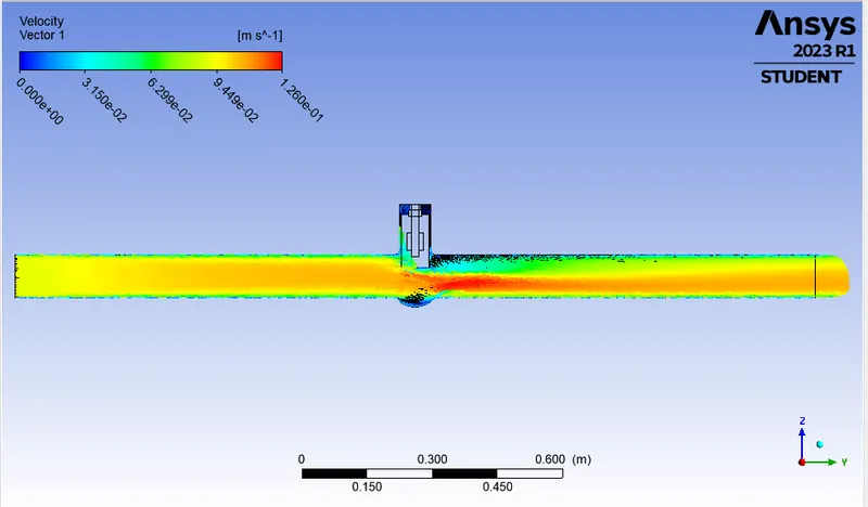
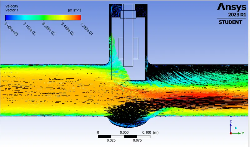
Please refer the below photo for the Streamline plot obtained.
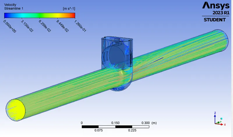
Please refer the below photo for the Animation of the model obtained.
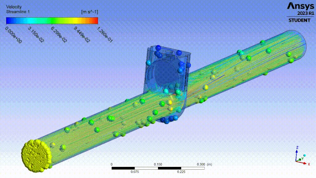
Please refer the below photo for the Results obtained.
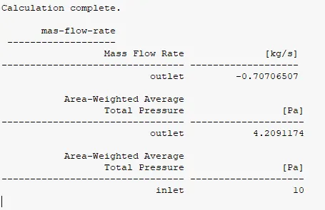
Results and Calculations:
Please refer the below parametric table obtained.
Please refer the below table for the calculations and results obtained.
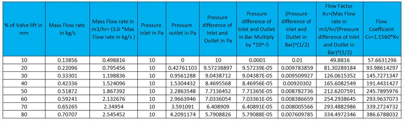
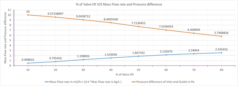
Please refer the below photo for the graph of % Valve lift in mm V/S Mass flow rate and Pressure difference.
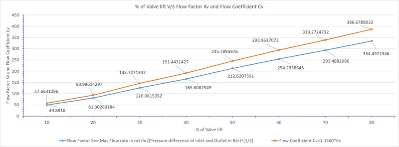
Please refer the below photo for the graph of % Valve lift in mm V/S Cv and Kv.
Conclusions:
- From the above it is concluded that the Mass Flow Rate increases with increase in the opening of the Gate Valve or Lift of the Gate Disc.
- Mass Flow Rate, Flow Coefficient and Flow Factor go linearly with Gate Disc Opening or from 10% to 80%, or 10 mm 80 mm.
- The negavite sign of mass flow rate denotes that the fluid discharges through outlet of Gate valve.
- Pressure drop will be gradually decreases as Lift of the Gate Disc increases.
- We can conclude from observations that velocity in the first case is very low. As opening or lift of the Gate Disc increases, velocity of the flow increases.
- When the valve if fully open, Mass Flow rate and Flow Coefficient and Flow Factor becomes maximum.
- Gate valve should operate in a fully-opened or fully-closed position. A partially-opened valve induces vibration which can damage the gate valve.
- Also the gate valve should be closed gradually rather than suddenly, as it causes a water hammer effect which can again damage the gate valve.