Week 4 Challenge : CFD Meshing for BMW car
Aim:
For the given BMW car model, check and solve all geometrical errors on half portion and Assign appropriate PIDs. Perform meshing with the given Target length and element Quality criteria. After meshing the half model, Do symmetry to the other side. Creating the wind tunal and also mesh it. At last perform volumetric meshing for both BMW car Body and Wind tunal.
Objectives:
Target lengths for the different parts of a model are as follow:
- Body - 3 mm
- Lights - 4 mm
- Grills - 1 mm
- Rims and Tyres - 2 mm
- Optical Rear view mirror - 2 mm
- Window - 2 mm
- Silencer - 3 mm
- Logo - 1 mm
- Wind tunal top face - 100 mm
- Wind tunal bottom face - 20 mm
- Wind tunal side faces - Manual spacing in between 20 mm and 100 mm
These target length and meshing is achieved by using CFD mesh, Element type- Tria, Element order - 1st order
Wind Tunal box dimensions calculations:
1)Creat a center point on the bottom surface of the car
2) Craet a point which is below the the center point i.e -200 mm in -ve Y direction so that we need to maintain some clearance from the car to the bottom of the wind tunal, let us consider this as point 1
3) Measure the total length of the car the approximate value as 1300mm ------i
4) Measure the distance between the point point 1 and the front end and back end of the car is approximatly +650 mm and -650 mm in +ve and -ve Z direction respectively---------ii
4) Measure the distance between the center point created on bottom surface of the car and right and left dead end of the car i.e approximatly +400 mm and -400 mm in +ve and -ve X direction respectively -----iii
5) Creat the point from point 1 i.e +650+(4*1300)=+5850mm ( from i and ii) at the front of the car in +ve Z direction let us consider this as point 2
6) Creat the point from the center point 1 i.e -650-(6*1300)=-8450mm (from i and ii) at the back of the car in -ve Z direction let us consider this as point 3
7) Creat the points at the right and left of the car with reference to the point 2, point 3 a i.e +400+1300=+1700 mm(from iii and ii) in +ve X direction and -400-1300=-1700 mm (from iii and ii) let us consider it as point 4, point 5 and point 6, point 7 respectively in +ve and -ve X direction.
Note: To creat the point uses the point tool i.e Classic Topo>Points > Relative.
Procedure :
Following steps were followed from geometry clean up to volumetric meshing.
Step 1: Geometry clean up / soving for the geometry error
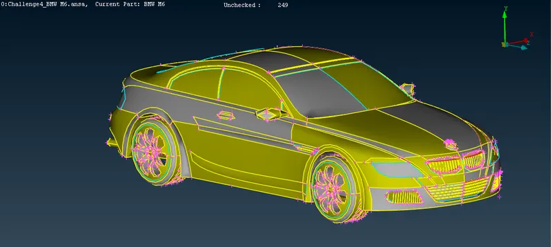
The given BMW car model has so many single cons and trippel cons we hvae to work it on then and clean the geometry.
Please refer the below photo for the model having geometrical error.
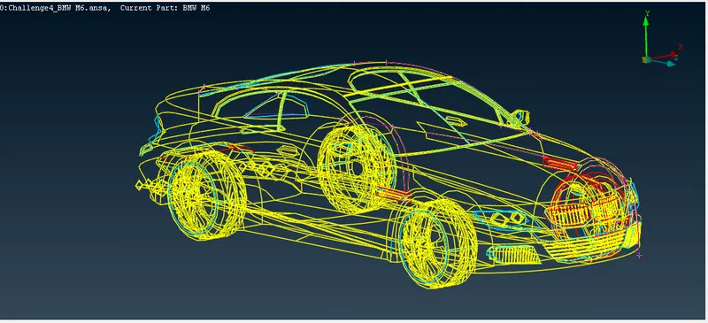
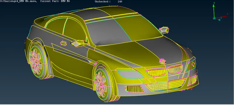
There is a unstructures sharp faces are there in the model we have change the resolution the surface. please refer the below photo of unresolved surfaces of the BMW model.
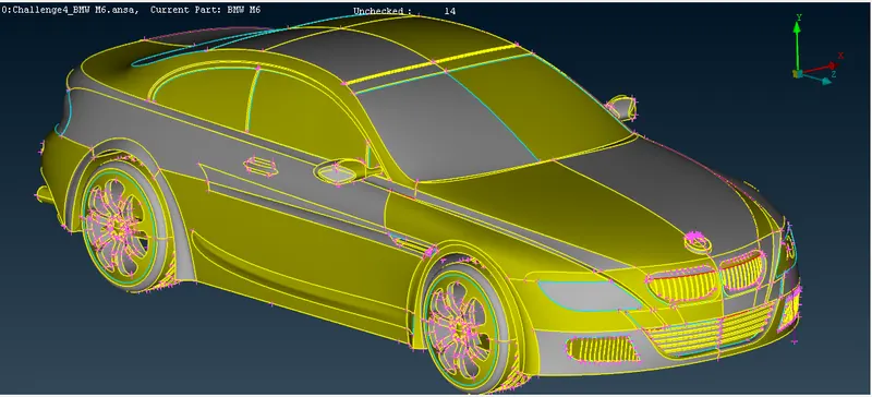
Go to classic mesh tool in that perimeter and length, box select the BMW whole car and give the length as 1 mm in both perimerers and Macros. Then we got the resolved model of the BMW car. Please refer the below photo for that.
We are going to delete the half portion of the BMW car and solve for the geometry. At last after meshing all the solved geometry we have to mirror the half part of the car to get the full model.
Please refer the below photo for the half portion of the BMW car to be solve for geometry and half portion BMW car with the geometry error.
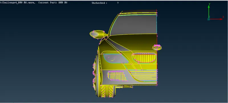
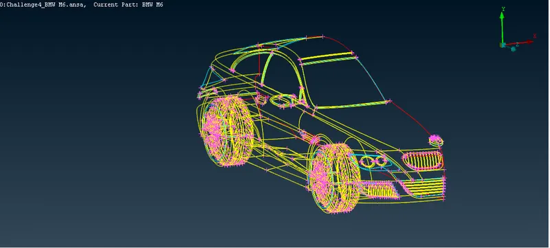
Following Classic Toopo tools were used while solving the geometry.
1) Hot Points > Insert, Delete, Project.
2) Cons > Fill hole.
3) Faces > New, Cut, Plane cut, Intersect, Extend,Delete.
4) Curves > Creat, Cons2curve, Delete.
Please refer the below photo for the solved geometry. There is no single cons and trippel cons.
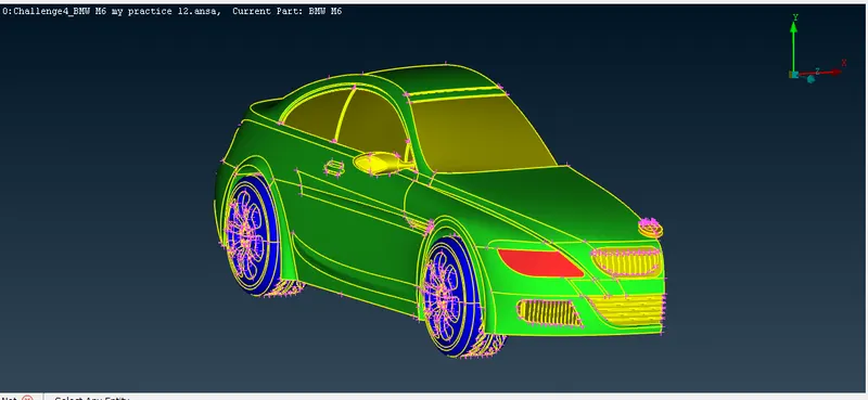
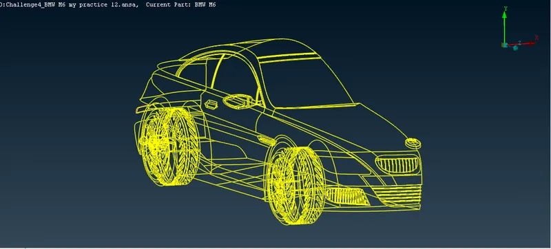
After solving all the geometry we should check the geometry as in the below photo. There should be no Penetration: Intersection error in the geometry, we can ignor the single cons, concve cons and convex cons in the geometry as these are all just warnings.
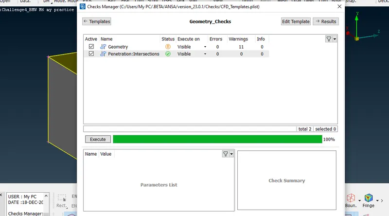
Step 2: Assigning the PID for the solved geometry.
Following PID's were assigned for the respective parts. Please refer the below photo for the assigned PID's from 61 to 68 ID
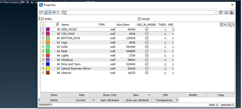
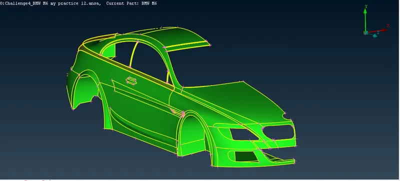
1) Body: Please refer the below photo for the body
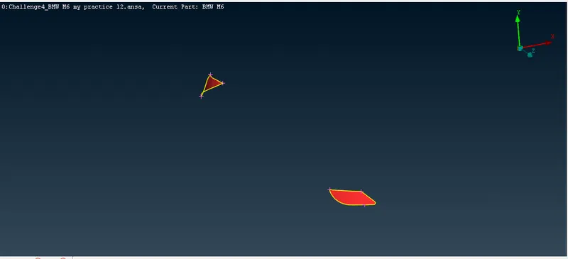
2) Lights: Please refer the below photo for the Lights
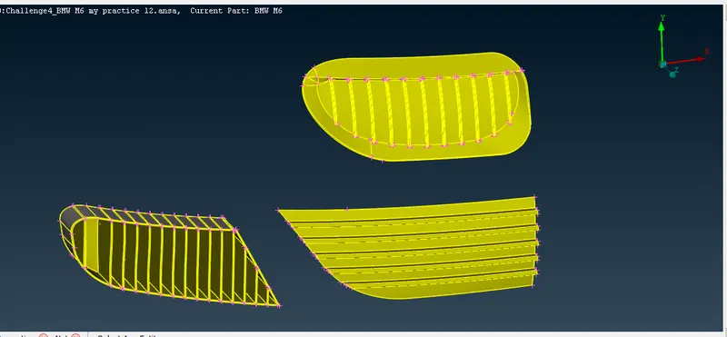
3) Grills: Please refer the below photo for the Grills
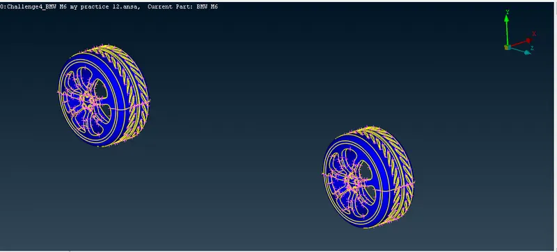
4) Rims and Tyres: Please refer the below photo for the Rims and Tyres
5) Optical Rear view mirror: Please refer the below photo for the Optical Rear view mirror
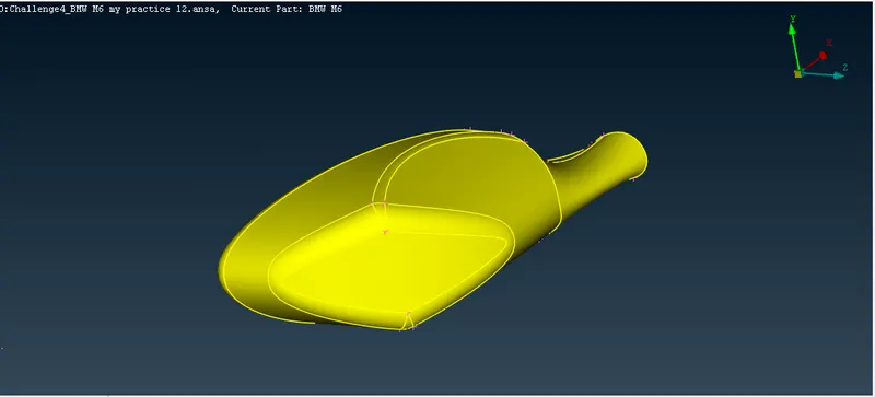
6) Window: Please refer the below photo for the Window
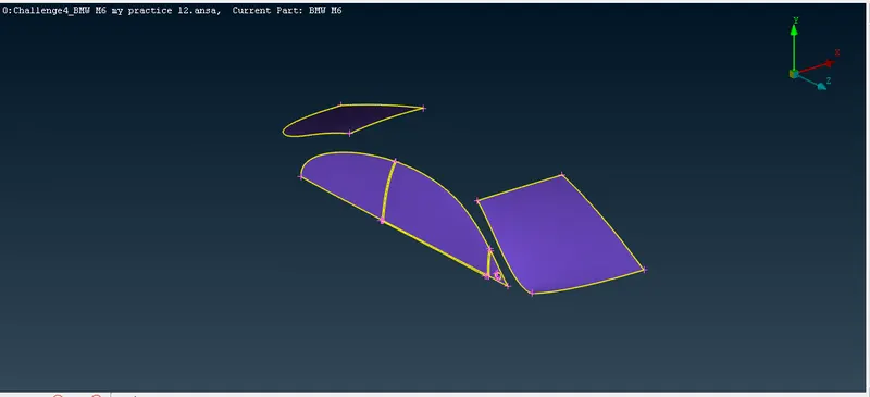
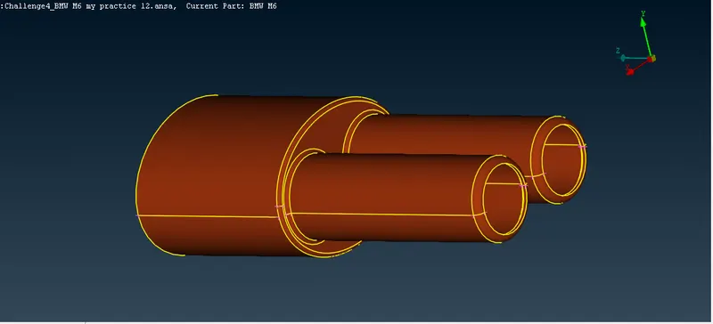
7) Silencer: Please refer the below photo for the Silencer
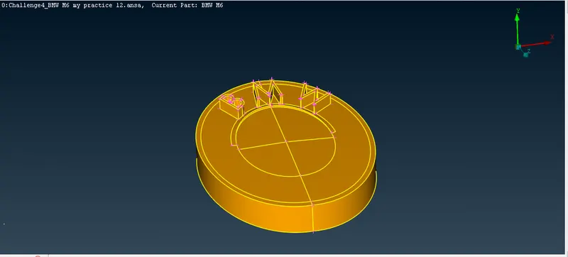
8) Logo: Please refer the below photo for the Logo
Note: Tools used in this step is PIDs
Step 3: Surface meshing for the Assigned PIDs
Below tools are used in the quality criteria and meshing parameters.
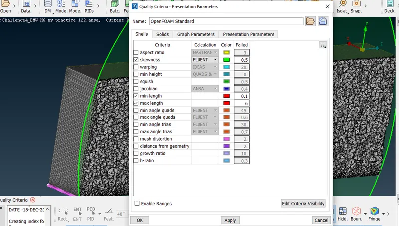
Quality criteria > Skewness, Failed value 0.5> Minimum Length, Failed value 0.1 mm > Maximum Length, Failed value 6 mm. Please refer the below photo for the Quality criteria applied.
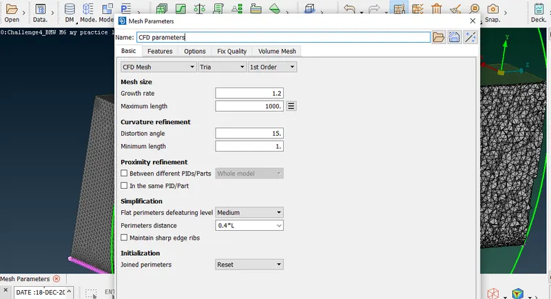
Meshing parameters > CFD mesh> Element type, Tria > Element order, 1st order. Please refer the below photo for the Meshing parameters applied.
Below tools are used in the surface meshing.
a) Classic mesh> Perimeters> Spacing> Auto CFD
b) Classic mesh> Mesh Generation > CFD Visible
c) Classic mesh> Macros> Freeze/Un
Please refer the below table for the quality criteria of surface meshing used for the different PIDs.
| PID name | Targeted Length in mm | Skewness | Minimum Length in mm | Maximum Length in mm |
| Grills | 1 mm | 0.5 | 0.1 mm | 1.2 mm |
| Logo | 1 mm | 0.5 | 0.1 mm | 1.2 mm |
| Rims and Tyres | 2 mm | 0.5 | 1 mm | 3 mm |
| Optical Rear view mirror | 2 mm | 0.5 | 1 mm | 3 mm |
| Window | 2 mm | 0.5 | 1 mm | 3 mm |
| Body | 3 mm | 0.5 | 2 mm | 4 mm |
| Silencer | 3 mm | 0.5 | 2 mm | 4 mm |
| Lights | 4 mm | 0.5 | 3.5 mm | 5.5 mm |
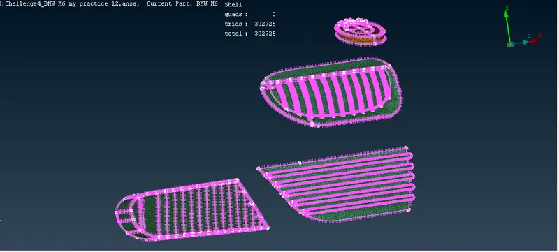
Please refer the below photo for the Grills and Logo meshed as in the above table quality criteria.
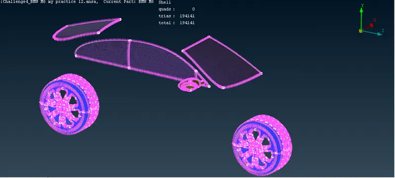
Please refer the below photo for the Rims and Tyres, Optical Rear View mirror and Window meshed as in the above table quality criteria.
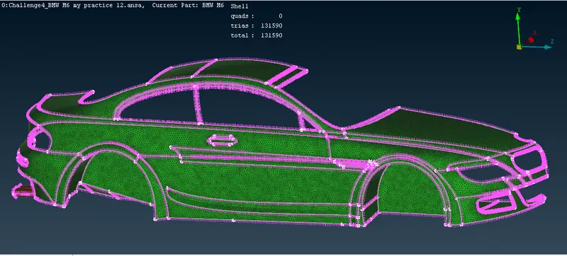
Please refer the below photo for the Body and Silencer meshed as in the above table quality criteria.
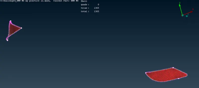
Please refer the below photo for the light meshed as in the above table quality criteria.
Note: At last we have to unfreeze the mesh and continue the further process.
Step 4: Creation the other half portion of the car by using Transform tool.
Mirror the half portion of the BMW whole car except logo by using Transfer tool.
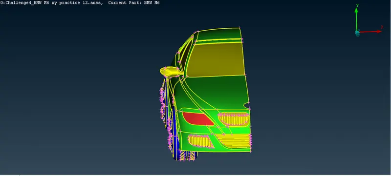
Please refer the below photo of half portion of the BMW whole car to be mirror.
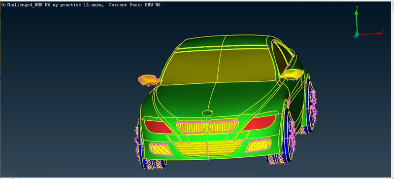
Please refer the below photo for the mirrored or complet BMW car model.
Step 5: Creation of Wind tunal, assigning the PIDs and it's surface meshing.
i) Following procedures were followed for the creation of Wind Tunal box with its dimensions calculations:
1)Creat a center point on the bottom surface of the car
2) Craet a point which is below the the center point i.e -200 mm in -ve Y direction so that we need to maintain some clearance from the car to the bottom of the wind tunal, let us consider this as point 1
3) Measure the total length of the car the approximate value as 1300mm ------i
4) Measure the distance between the point point 1 and the front end and back end of the car is approximatly +650 mm and -650 mm in +ve and -ve Z direction respectively---------ii
4) Measure the distance between the center point created on bottom surface of the car and right and left dead end of the car i.e approximatly +400 mm and -400 mm in +ve and -ve X direction respectively -----iii
5) Creat the point from point 1 i.e +650+(4*1300)=+5850mm ( from i and ii) at the front of the car in +ve Z direction let us consider this as point 2
6) Creat the point from the center point 1 i.e -650-(6*1300)=-8450mm (from i and ii) at the back of the car in -ve Z direction let us consider this as point 3
7) Creat the points at the right and left of the car with reference to the point 2, point 3 a i.e +400+1300=+1700 mm(from iii and ii) in +ve X direction and -400-1300=-1700 mm (from iii and ii) let us consider it as point 4, point 5 and point 6, point 7 respectively in +ve and -ve X direction
8) Join the point 2, point 3, point 4, point 5, point 6 and point 7 by using curves tool i.e Classic Topo> curves> Creat> Curve
9) Creat a Bottom face for the above joined points by using face tool i.e creat. We have created the bottom face of the tunal.
10) Creat a point at the top of the car i.e +3*1300=+3900mm in +ve Y direction and measure the distance between this point and point 1 i.e 4420 mm. Creat a face on this point by using face tool i.e offset and offst value is -4420 mm don't delete the original face. Now we have createad a top face of the tunal.
11) With reference to the top and bottom face tunal creat the entire side face of the tunal.
12) At last delete all the Points created and curves too.
Note: To creat the point uses the point tool i.e Classic Topo>Points > Relative.
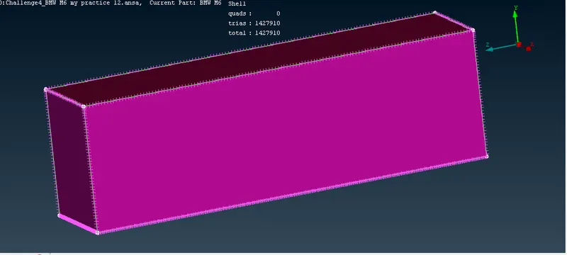
Please refer the below photo for the tunal created
ii) Assigning the PIDs for the Top, Bottom and side faces of the Wind tunal
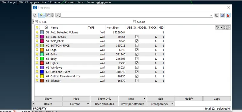
Please refer the below photo for the assigning the PIDs using PID tool.I created the PIDs 58, 59 and 60 as in the photo.
ii) Surface Meshing the Wind tunal
1) Bottom face is meshed with the target length of 20 mm with the quality criteria of skewness 0.5, Minimum Length 1 mm and maximum lemgth 30 mm.
2) Top face is meshed with the target length of 100 mm with the quality criteria of skewness 0.5, Minimum Length 90 mm and maximum lemgth 110 mm.
3) Side face is meshed by spacing manual with Minimum Length 1 mm and maximum lemgth 110 mm.
Note: Following Tools used are used
a) Classic mesh> Perimeters> Spacing> Auto CFD, this is for both Bottom and Top face
b) Classic mesh> Mesh Generation > CFD Visible, this is for both Bottom and Top face
c) Classic mesh> Perimeters> Spacing>Manual, this is for side face
Refer the below photo for the Bottom face mesh obtained
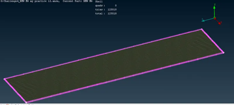
Refer the below photo for the Top face mesh obtained
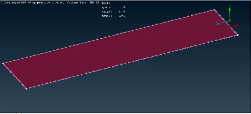
Refer the below photo for the Side face mesh obtained
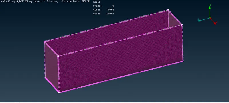
Step 6: Volumetric meshing for the above surface meshed Wind Tunal and BMW car Body.
After the surface meshing we are going for volumetric mesh for wind tunal and BMW car body only. Tools used is Classic mesh> Volumes > Define.
Select the PID which is only Wind tunal and BMW car body. please refer the below photo for the volome PID number 51.
At last go for volumetric mesh and refer the belw photo for the volometric mesh obtained.
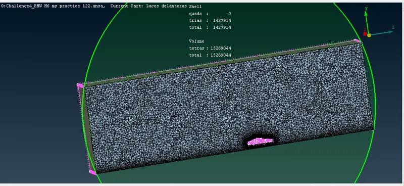
Please refer the below link for the Volumetric meshed model of BMW car.
https://drive.google.com/file/d/14ZbgaHW00CofGXUul7DOzcmElFlWM_6X/view?usp=sharing