Project 1 : CFD Meshing for Tesla Cyber Truck
Aim:
For the given Tesla cyber truck model, check and solve all geometrical errors on half portion and assign appropriate PIDs. Perform meshing with the desired Target length and element Quality criteria. After meshing the half model, Do symmetry to the other side. Creating the wind tunnel and also mesh it.
Objectives:
Target lengths for the different parts of a model is as follow:
- Tyres and Windows - 2 mm
- Body - 4 mm
- Wind tunnel top face - 100 mm
- Wind tunnel bottom face - 20 mm
- Wind tunnel side faces - Manual spacing in between 20 mm and 100 mm
These target length and meshing is achieved by using CFD mesh, Element type- Trai, Element order - 1st order
Wind tunnel box dimensions calculations:
1)Create a centre point on the bottom surface of the Tesla cyber truck
2) Crate a point which is below the centre point i.e -1000 mm in -ve Z direction so that we need to maintain some clearance from the truck to the bottom of the wind tunnel, let us consider this as point 1
3) Measure the total length of the truck the approximate value as 6000mm ------i
4) Measure the distance between the point 1 and the front end and back end of the truck is approximately -2600 mm and +3400 mm in -ve and +ve Y direction respectively---------ii
4) Measure the distance between the centre point created on bottom surface of the Truck and right and left dead end of the truck i.e approximately +1000 mm and -1000 mm in +ve and -ve X direction respectively -----iii
5) Create the point from point 1 i.e -2600+(4*6000)=-26600mm ( from i and ii) at the front of the car in -ve Y direction let us consider this as point 2
6) Create the point from the centre point 1 i.e +3400+(6*1300)=+39400 mm (from i and ii) at the back of the Truck in +ve Y direction let us consider this as point 3
7) Create the points at the right and left of the truck with reference to the point 2, point 3 a i.e +1000+6000=+7000 mm(from iii and ii) in +ve X direction and -1000-6000=-7000 mm (from iii and ii) let us consider it as point 4, point 5 and point 6, point 7 respectively in +ve and -ve X direction.
Note: To create the point uses the point tool i.e Classic Toppo>Points > Relative.
Procedure :
Following steps were followed from geometry clean up to volumetric meshing.
Step 1: Geometry clean-up / saving for the geometry error
The given Tesle cyber truck model has so many single cons and Trippel cons we have to work it on that and clean the geometry.
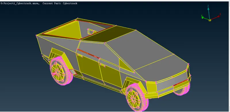
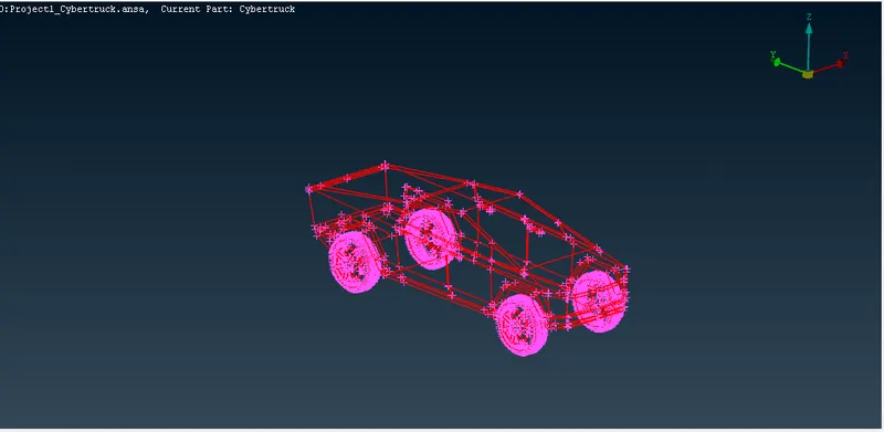
Hit a toppo and start cleaning the geometry.
Close the back window of the tesla cyber truck as shown in the below photo.
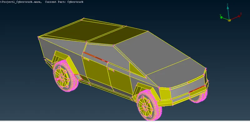
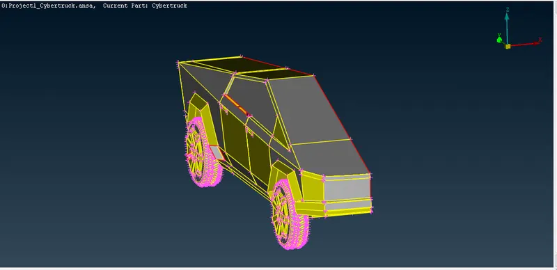
We are going to delete the half portion of the Tesla cyber truck and solve for the geometry. At last, after meshing all the solved geometry we have to mirror the half part of the car to get the full model.
Please refer the below photo for the half portion of the Tesla cyber truck to be solve for geometry and half portionof the tesla cyber truck with the geometry error.
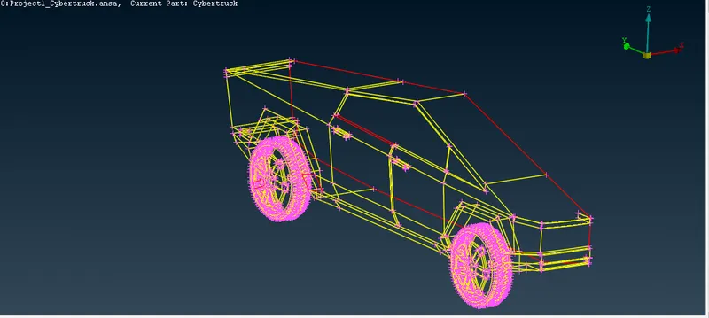
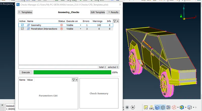
Following Classic Toppo tools were used while solving the geometry.
1) Hot Points > Insert, Delete, Project.
2) Cons > Fill hole.
3) Faces > New, Cut, Plane cut, Intersect, Extend, Delete.
4) Curves > Create, Cons2curve, Delete.
Please refer the below photo for the solved geometry. There is no single cons and Trippel cons.
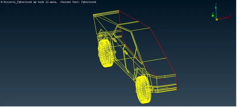
Step 2: Assigning the PID for the solved geometry.
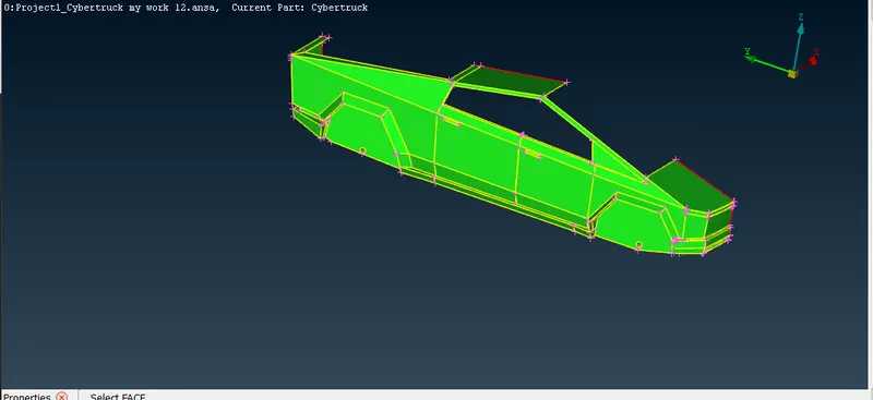
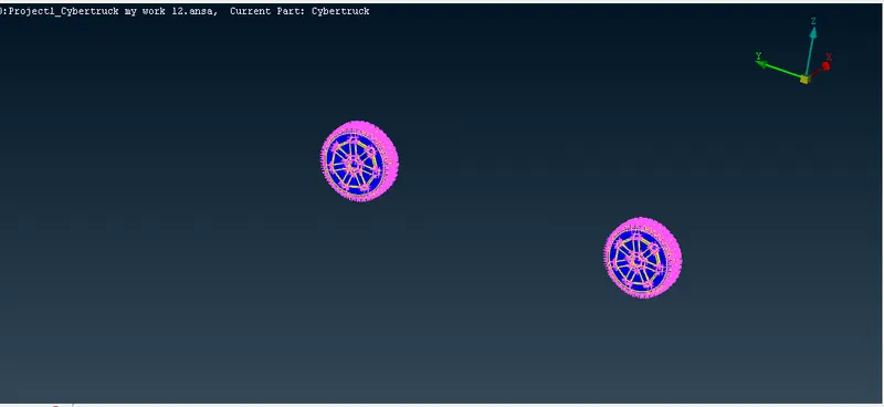
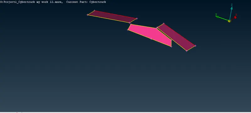
Following PID's were assigned for the respective parts. Please refer the below photo for the assigned PID's from 178 to 180 ID. Use the Compress to remove the empty PIDs.
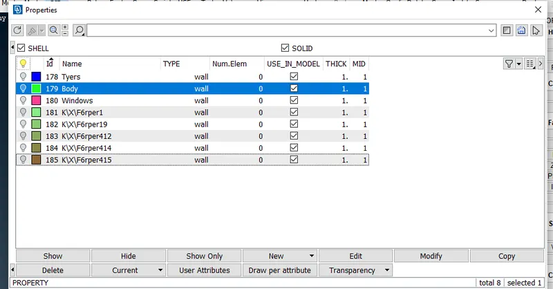
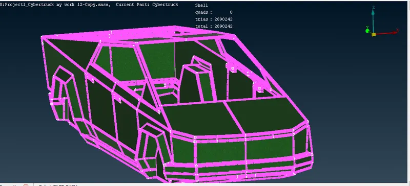
Body: Please refer the below photo for the body PIDs assigned
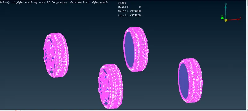
Tyres: Please refer the below photo for the Tyres PIDs assigned
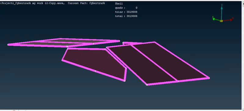
Windows: Please refer the below photo for the windoes PIDs assigned
Note: Tools used in this step is PIDs
Step 3: Surface meshing for the Assigned PIDs
Below tools are used in the quality criteria and meshing parameters.
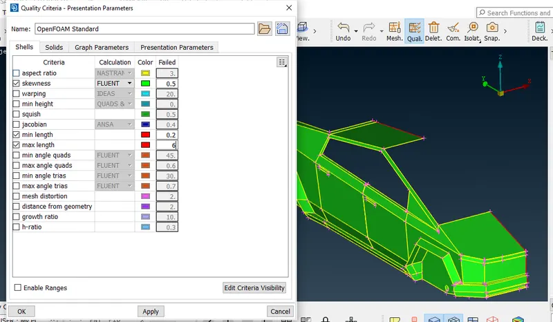
Quality criteria > Skewness, failed value 0.5> Minimum Length, Failed value 0.2 mm > Maximum Length, Failed value 6 mm. Please refer the below photo for the Quality criteria applied.
Meshing parameters > CFD mesh> Element type, Tria > Element order, 1st order. Please refer the below photo for the Meshing parameters applied.
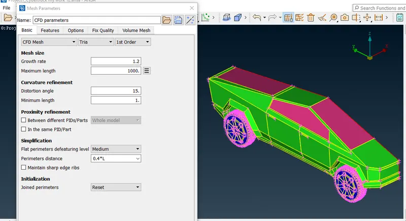
Below tools are used in the surface meshing.
a) Classic mesh> Perimeters> Spacing> Auto CFD
b) Classic mesh> Mesh Generation > CFD Visible
c) Classic mesh> Macros> Freeze/Un
Please refer the below table for the quality criteria of surface meshing used for the different PIDs.
|
PID name |
Targeted Length in mm |
Skewness |
Minimum Length in mm |
Maximum Length in mm |
|
Tyres and window |
2 mm |
0.5 |
1.7 mm |
2.3 mm |
|
Body |
4 mm |
0.5 |
3 mm |
5 mm |
Please refer the below photo for the Tyres and window meshed as in the above table quality criteria freeze the mesh and continue.
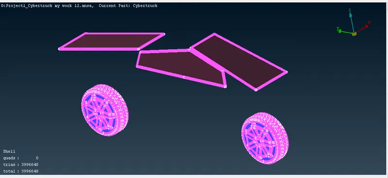
Please refer the below photo for the Body meshed as in the above table quality criteria.
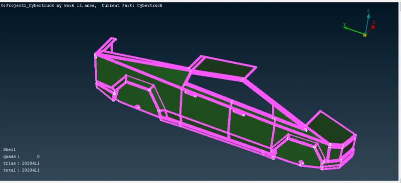
Note: At last, we have to unfreeze the mesh and continue the further process
Step 4: Creation the other half portion of the car by using Transform tool.
Mirror the half portion of the BMW whole car except logo by using Transfer tool.
Please refer the below photo of half portion of the Tesla cyber truck to be mirror.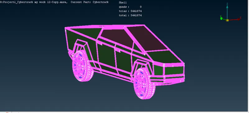
Please refer the below photo for the mirrored or complete Tesla cyber truck.
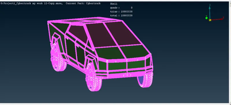
Step 5: Creation of Wind tunnel, assigning the PIDs and it's surface meshing.
i) Following procedures were followed for the creation of Wind tunnel box with its dimensions calculations:
1)Create a centre point on the bottom surface of the Tesla cyber truck
2) Crate a point which is below the centre point i.e -1000 mm in -ve Z direction so that we need to maintain some clearance from the truck to the bottom of the wind tunnel, let us consider this as point 1
3) Measure the total length of the truck the approximate value as 6000mm ------i
4) Measure the distance between the point 1 and the front end and back end of the truck is approximately -2600 mm and +3400 mm in -ve and +ve Y direction respectively---------ii
4) Measure the distance between the centre point created on bottom surface of the Truck and right and left dead end of the truck i.e approximately +1000 mm and -1000 mm in +ve and -ve X direction respectively -----iii
5) Create the point from point 1 i.e -2600+(4*6000)=-26600mm ( from i and ii) at the front of the car in -ve Y direction let us consider this as point 2
6) Create the point from the centre point 1 i.e +3400+(6*1300)=+39400 mm (from i and ii) at the back of the Truck in +ve Y direction let us consider this as point 3
7) Create the points at the right and left of the truck with reference to the point 2, point 3 a i.e +1000+6000=+7000 mm(from iii and ii) in +ve X direction and -1000-6000=-7000 mm (from iii and ii) let us consider it as point 4, point 5 and point 6, point 7 respectively in +ve and -ve X direction.
8) Join the point 2, point 3, point 4, point 5, point 6 and point 7 by using curves tool i.e Classic Toppo> curves> Create> Curve
9) Create a Bottom face for the above joined points by using face tool i.e create. We have created the bottom face of the tunnel.
10) Create a point at the top of the car i.e +3*6000=+1800mm in +ve Z direction and measure the distance between top of the tesla cyber truck and point 1 i.e 1600 mm. Create a face on this point by using face tool i.e offset and offst value is +19600 mm and don't delete the original face. Now we have created a top face of the tunnel.
11) With reference to the top and bottom face tunnel create the entire side face of the tunnel.
12) At last, delete all the Points created and curves too.
Note: To create the point uses the point tool i.e Classic Toppo>Points > Relative.
Please refer the below photo for the tunnel created
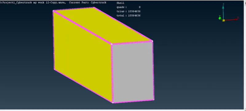
- ii) Assigning the PIDs for the Top, Bottom and side faces of the Wind tunnel
Please refer the below photo for the assigning the PIDs using PID tool. I created the PIDs 175, 176 and 177 as in the photo.
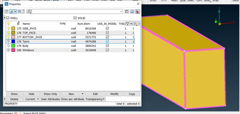
- ii) Surface Meshing the Wind tunnel
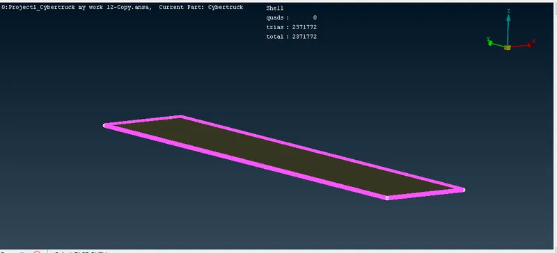
1) Bottom face is meshed with the target length of 20 mm with the quality criteria of skewness 0.5, Minimum Length 1 mm and maximum length 30 mm.
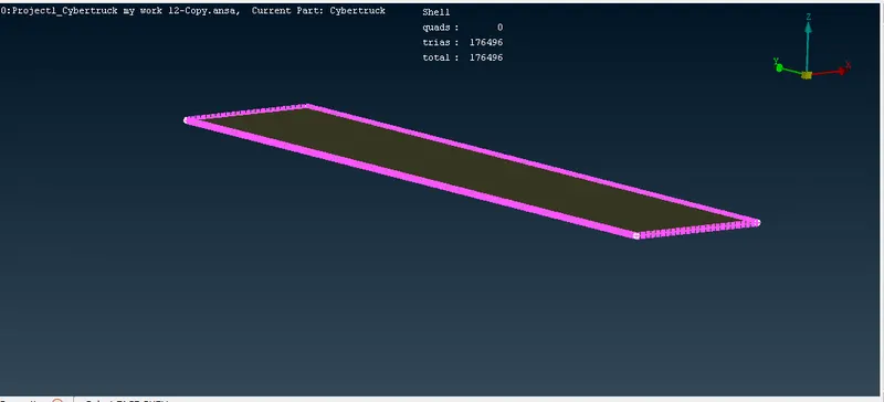
2) Top face is meshed with the target length of 100 mm with the quality criteria of skewness 0.5, Minimum Length 90 mm and maximum length 110 mm.
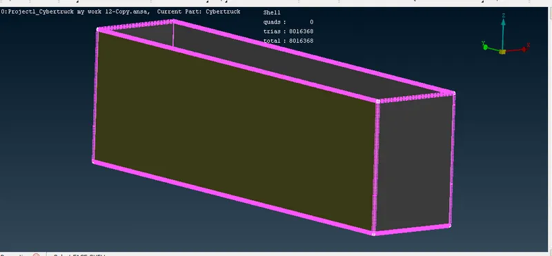
3) Side face is meshed by spacing manual with Minimum Length 1 mm and maximum length 110 mm.
Note: Following Tools used are used
- a) Classic mesh> Perimeters> Spacing> Auto CFD, this is for both Bottom and Top face
- b) Classic mesh> Mesh Generation > CFD Visible, this is for both Bottom and Top face
- c) Classic mesh> Perimeters> Spacing>Manual, this is for side face
Refer the below photo for the Top, Bottom face and Side face mesh obtained
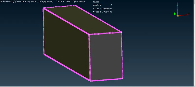
Learning out comes:
Following are the learning out comes from this project.
- Geometry clean up for the given model by toppo tool.
- Assigning the PIDs for the different parts.
- Surface meshing of the difined PIDs with Quality criteria and mesh parameters.
- Creating the wind tunnel for the desired length of the tesla cybertruck model.
- Assigning the PIDs for the wind tunnel and surface meshing of it
Result:
|
PID name |
Trias obtained |
|
Body |
2890242 elements |
|
Tyers |
4974288 elements |
|
Windows |
3019008 elements |
|
Wind tunnel Top Face |
176496 elements |
|
Wind tunnel Bottom Face |
2371772 elements |
|
Wind tunnel Side Face |
8016368 elements |
|
Total elements obtained |
21448174 elements |
Please refer the below photos for the body, tyres, windows, Wind tunnel top, bottom and side face Total Trias elaments obtained respectively.
Please refer the below link for the Tesla cyber truck model solved and obtained as in the above result using ANSA software.
https://drive.google.com/file/d/18_B--iGVXPBVWxI4D0aS4epbPUmIA0as/view?usp=sharing