Week 9 - Parametric study on Gate valve.
PARAMETRIC STUDY ON GATE VALVE
AIM:
To perform simulation on Gate valve and to analyse the flow behaviour for different design point (lift positions).
Gate Valve:
A gate valve, also known as a slice valve, is a valve that opens by lifting a barrier (gate) out of the path of the fluid. Gate valves require very little space along the pipe axis and hardly restrict the flow of fluid when the gate is fully opened. The gate faces can be parallel but are most commonly wedge-shaped (in order to be able to apply pressure on the sealing surface).
Parametric Study:
Parametric study in Ansys Fluent is a method that map changes in inputs to the corresponding output. As long as the input parameter and output parameter are connected, the corresponding output values for change in input values are obtained.
MODELLING APPROACH:
Importing the Geometry
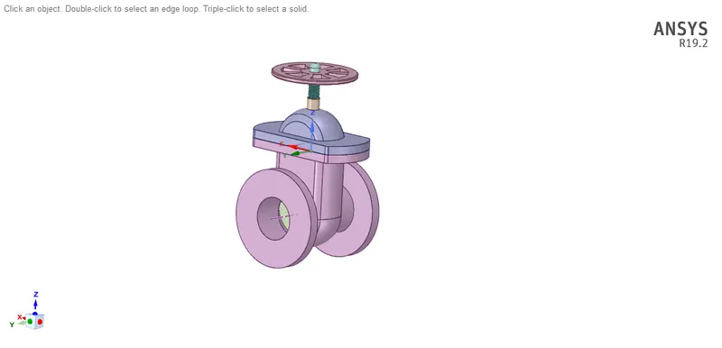
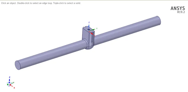
Extracting the Fluid Volume,
For Case 1 of 10 mm Lift,
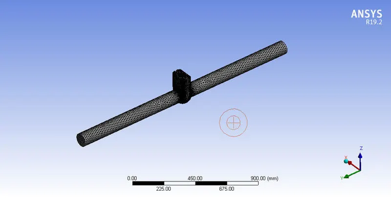
MESHING:
| Mesh Parameters | |
| Mesh Size | 100mm |
| Nodes | 28903 |
| Elements | 136871 |
SOLVER SETUP:
For Case 1 of 10 mm Lift,
| SOLVER INPUTS | |
| Solver Time | Steady |
| Solver Type | Pressure Based |
| Gravity | -9.81 in Zdirection |
| Energy | Off |
| Models | K Epsilon | Realizable |
| Materials | Water |
| Iterations | 250 |
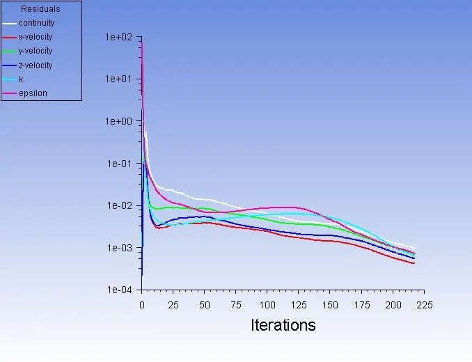
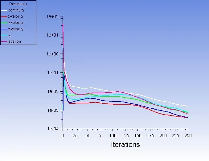
Residual Plot,
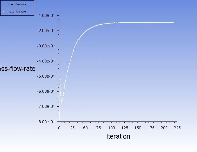
Mass Flow Rate plot,
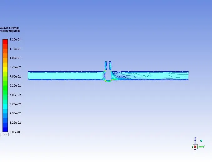
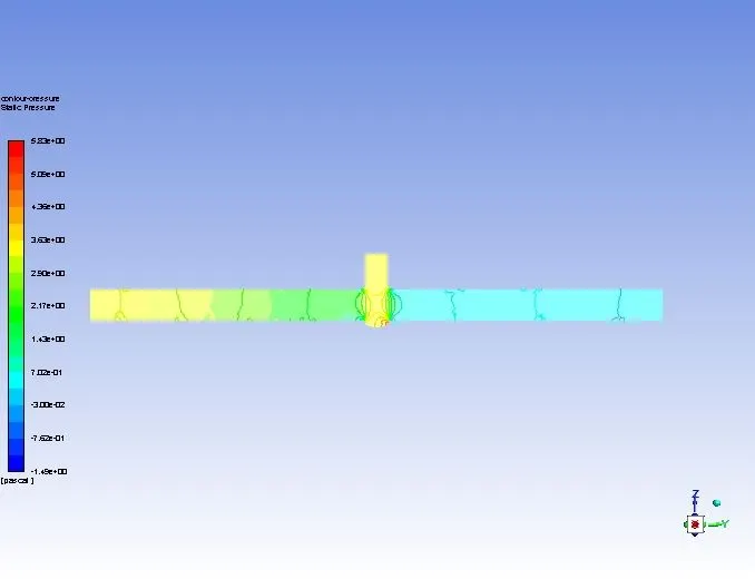
Pressure Contour Plot,
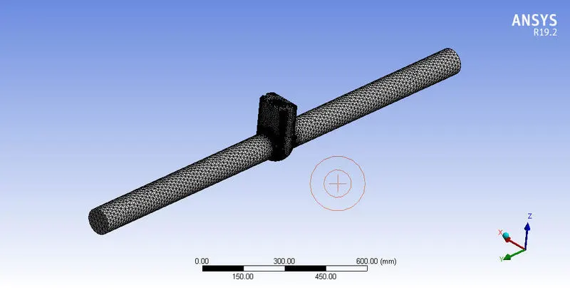
FOR CASE 2 OF 30MM LIFT,
| Mesh Parameters | |
| Mesh Size | 100mm |
| Nodes | 28780 |
| Elements | 136678 |
| Valve Lift | 30mm |
SOLVER INPUT:
| SOLVER INPUTS | |
| Solver Time | Steady |
| Solver Type | Pressure Based |
| Gravity | -9.81 in Zdirection |
| Energy | Off |
| Models | K Epsilon | Realizable |
| Materials | Water |
| Iterations | 250 |
Residual Plot,
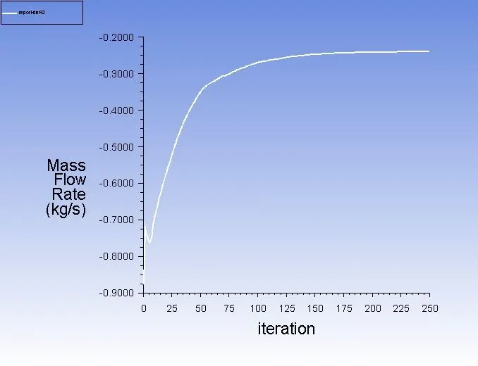
mass flow rate,
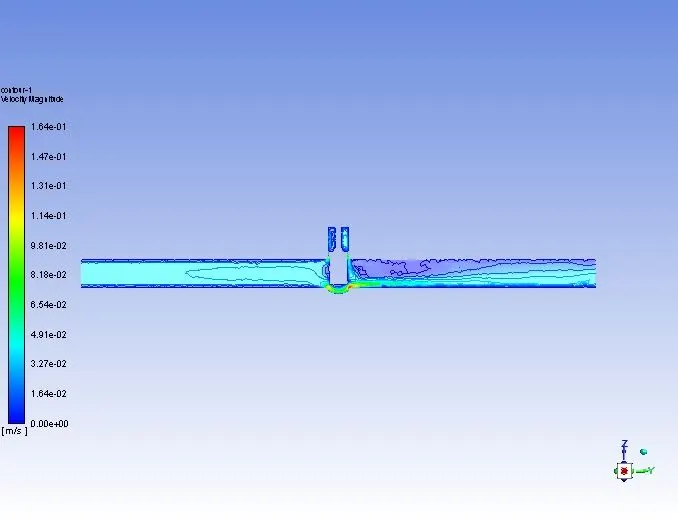
Pressure contour plot,
FOR 50 MM LIFT,
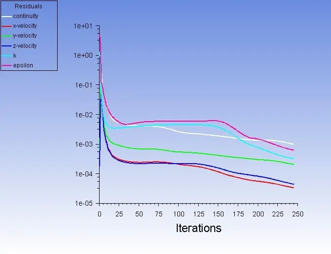
Residual Plot,
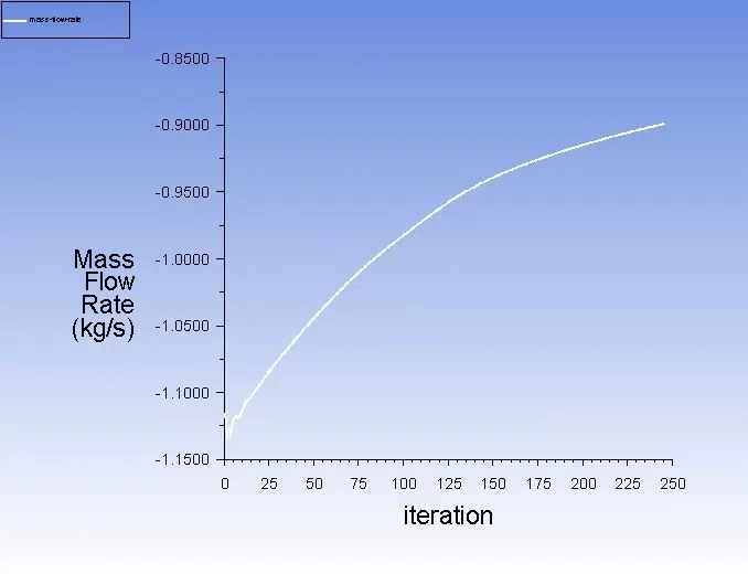
Mass Flow Rate plot,
Pressure contour plot,
SUMMARY OF RESULTS:
| Design point (Lever Position) | Lift Distance (mm) | Mass Flow rate @ outlet (Kg/s) |
| DP1 | 10 | -0.148374 [kg s^-1] |
| DP2 | 30 | -0.237759 [kg s^-1] |
| DP3 | 50 | -0.89813 [kg s^-1] |
Flow coefficient and flow factor,
Flow Coefficient(Cv):
Flow coefficient is a device’s capacity for a liquid or gas flow through it. The larger the opening of the valve the larger the Cv.
Mathematically the flow coefficient Cv (or flow-capacity rating of the valve) can be expressed as :
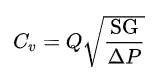
where:
Q is the rate of flow (expressed in US gallons per minute),
SG is the specific gravity of the fluid (for water = 1),
ΔP is the pressure drop across the valve (expressed in psi).
Flow Factor(Kv)
The metric equivalent flow factor (Kv; commonly used in Europe and Asia) is calculated using metric units :
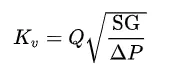
where
Kv is the flow factor (expressed in m^(3)*h^(-1)*bar^(-0.5)).
Q is the flow rate (expressed in cubic meters per hour)
SG is the specific gravity of the fluid (for water = 1),
∆P is the differential pressure across the device (expressed in [bar]).
Kv can be calculated from Cv using the equation
Kv=0.865*Cv
Calculation for Flow Coefficient,
Q = 1kg/s = 3.6 m^3/hr
P = 10-0 = 10 Pa = 10*10^(-5) bar = 10^(-4) bar
10 mm lift,
Cv=3.6*0.148374*√(1/10^-4) = 53.41464
30 mm lift,
Cv=3.6*0.237759*√(1/10^-4) =85.59
50 mm Lift,
Cv=3.6*0.89813*√(1/10^-4) =323.3268
Calculation of Flow Factor,
Kv=0.865*Cv,
For 10 mm Lift,
Kv=0.865* 53.41464 = 46.2036636
For 30 mm Lift,
Kv=0.865*85.59 = 74.03535
For 550 mm Lift,
Kv=0.865*323.3268 = 279.677682
CONCLUSION;
Simulation of flow through the gate valve for various design point is carried out and calculation of flow coefficient and
flow factor at different positions of the valve lift is calculated and the results are plotted.