Week 9 - Parametric study on Gate valve.
Gate valve challenge
Aim: To understand the use of parametric option using gate valve case study.
Introduction: Gate valve is a device used to manually control the flow of liquid. It is connected between two pipes. Gate valves are used in all chemical industries, petroleum industries, thermal power plants or any industry which relates to processing of liquids.
Theory: Gate valve contains handle which is connected to spindle which can move the gate up and down. In this way, the flow rate of liquid can be controlled. To simulate the flow for each opening, instead of creating different cases in workbench, a parametric option is selected, which allows to change the fixed parameter and gives the output in single program. It saves time for creating different cases and solving it separately. Here, we can provide different input at one place and get the desired results.
Solving and modelling approach:
In spaceclaim section, gate is moved by some distance and this distance is selected as parameter. So, when we want to check the results at different gate position, we can just change the distance at the parametric window.
In challenge, simulation is be done on 10% to 80% gate opening. As the diameter of the pipe was measured as 100 mm, 10% opening is considered as 10 mm opening.
Total 8 cases were discussed - 10, 20, 30, 40, 50, 60, 70, 80 mm opening.
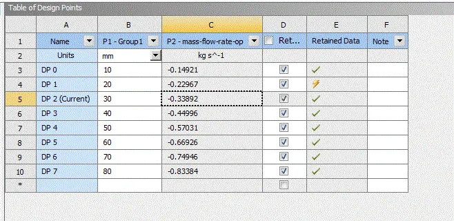
Mass flow rate was checked at each gate valve opening.
Flow factor was calculated as:
Kv = Q x sq.rt(specific gravity/pressure drop)
Where as, Q is in m3/h, pressure drop in bar
Flow coefficient was calculated as:
Cv = Kv/0.865
Pre-processing and solver settings:
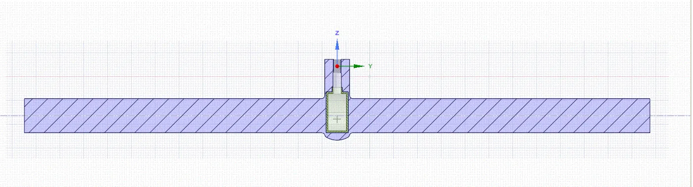
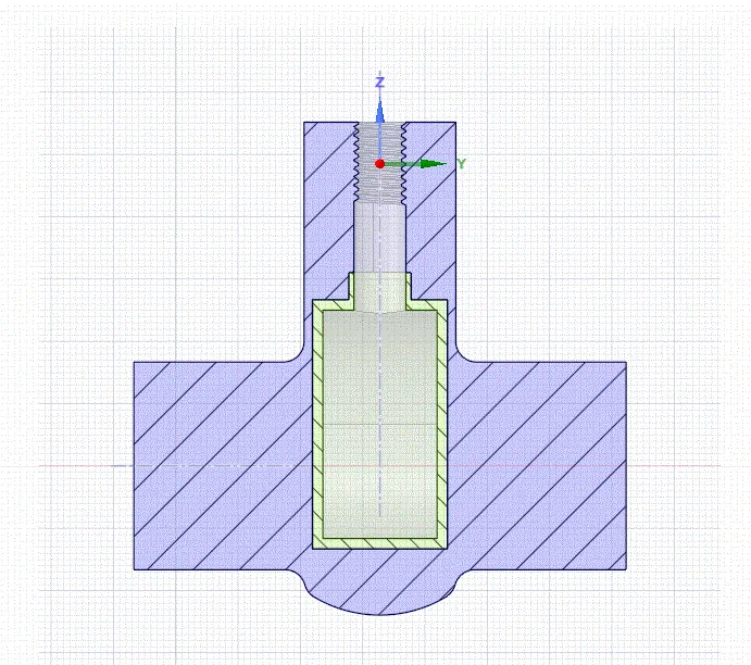
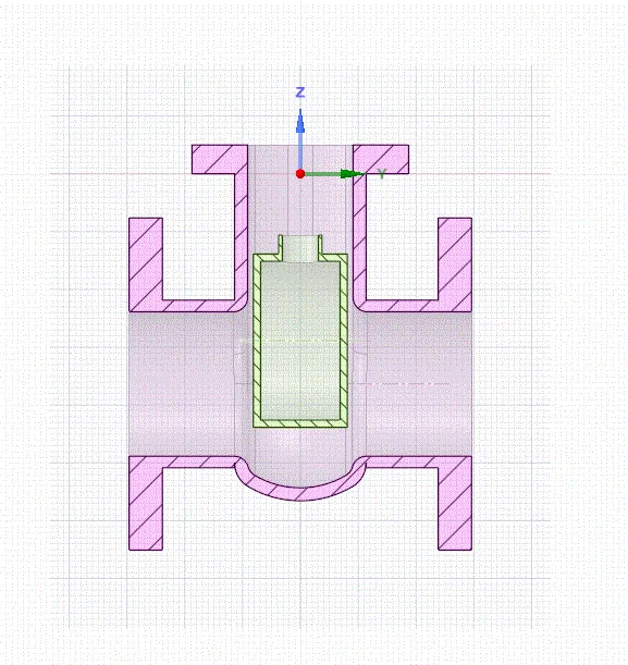
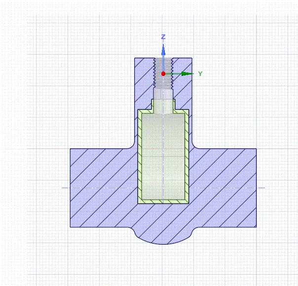
Geometry: Geometry was imported in spaceclaim. Different cases are presented as follows:
With 10 mm opening:
With 20 mm opening:
With 30 mm opening:
With 40 mm opening:
With 50 mm opening:
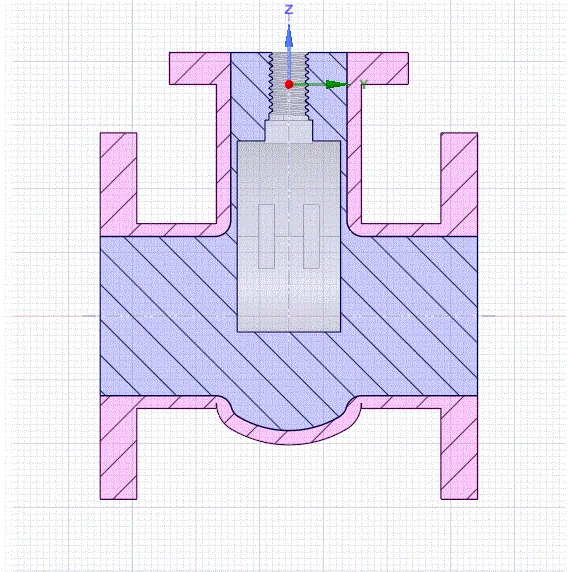
With 60 mm opening:
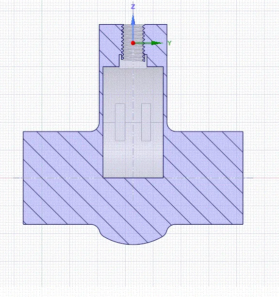
With 70 mm opening:
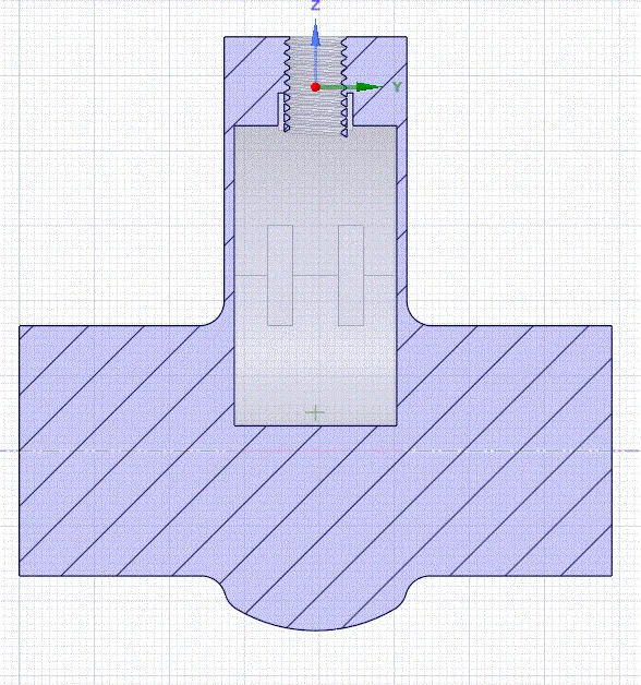
With 80 mm opening:
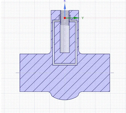
Mesh settings:
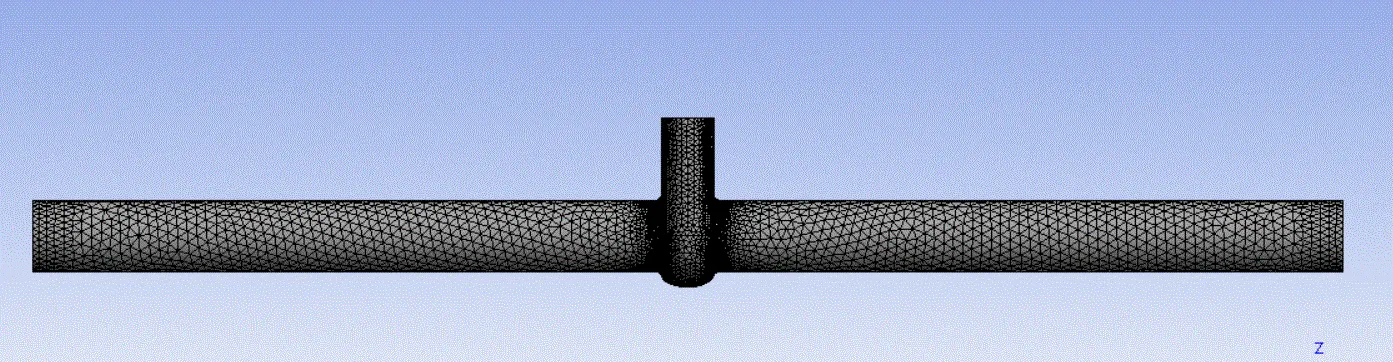
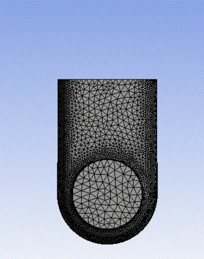
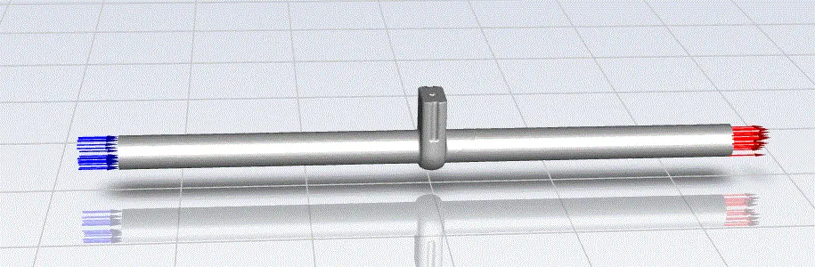
Mesh settings was kept same for all cases. Inlet and outlet were provided as named selections.
Body sizing with element size of 50 mm was given.
Face sizing with 10 mm element size was given.
Total element count was 139245.
Setup:
Steady state, gravity was enabled in Z direction.
K-epsilon model was selected with enhanced wall treatment.
Water was used as material. Pressure inlet was provided - 10 Pa.
Mass flow rate was obtained as output with different gate openings.
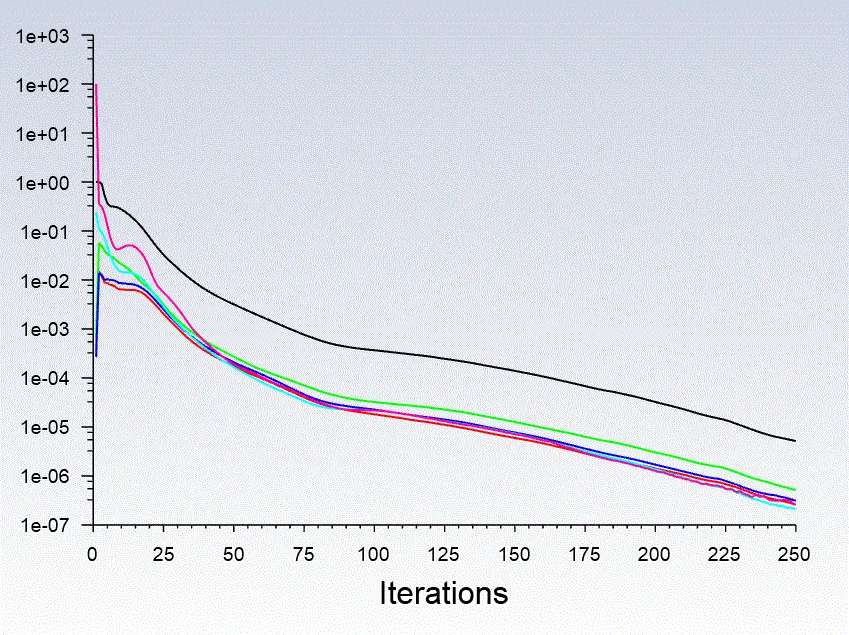
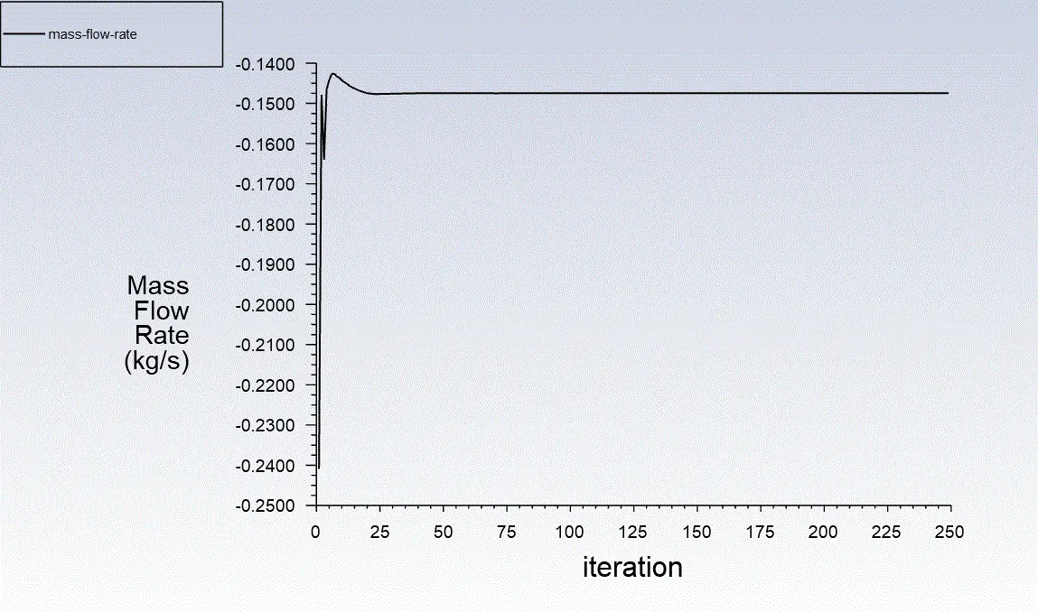
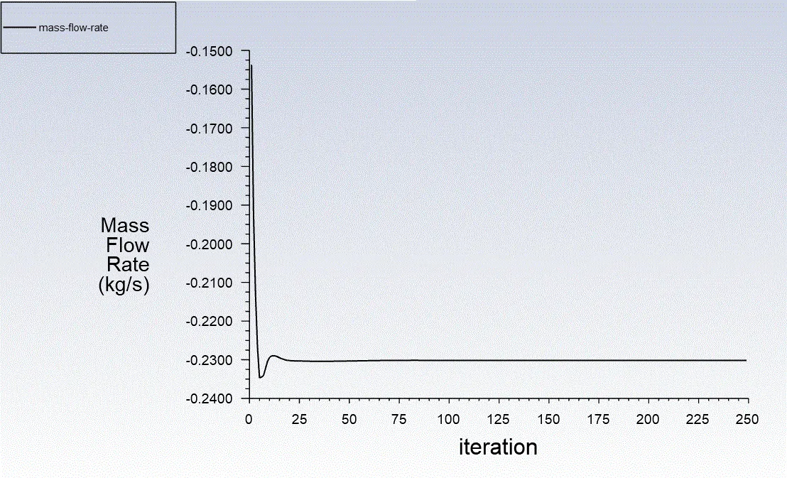
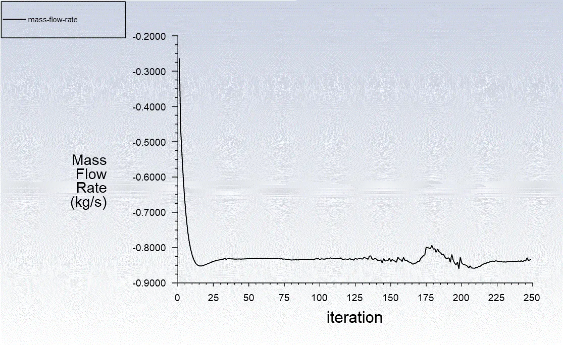
Convergence graph was similar in all cases after 250 iterations.
Results:
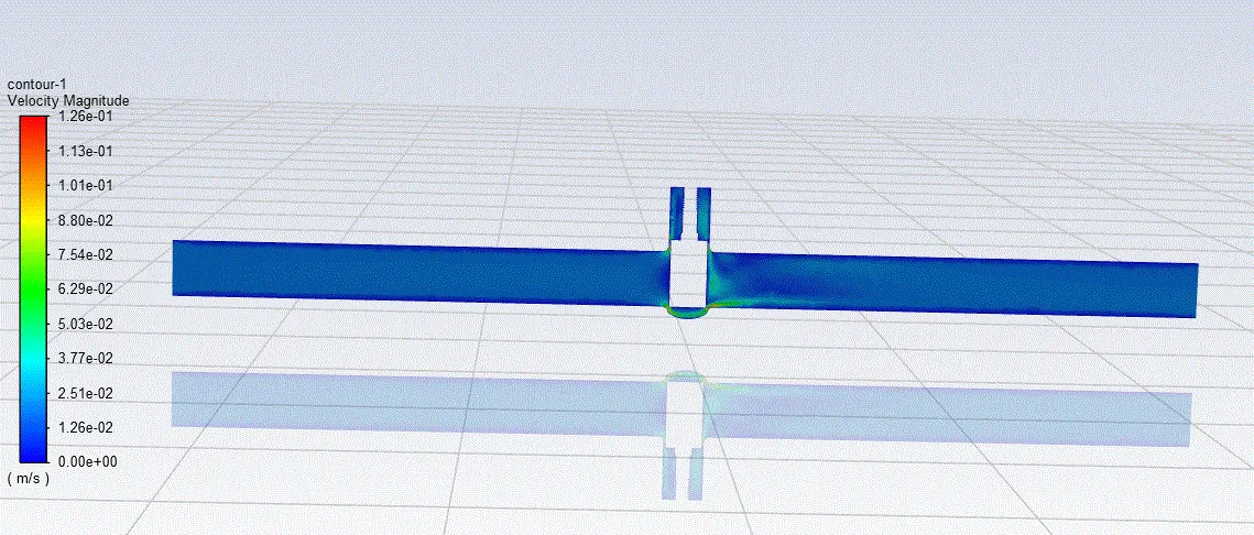
10 mm case:
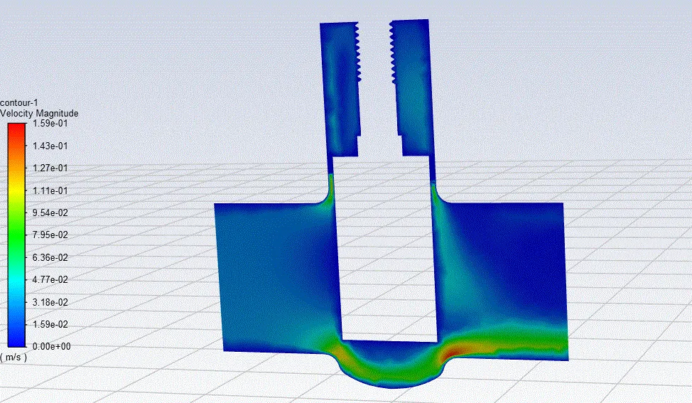
20 mm case:
30 mm case:
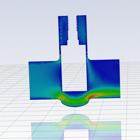
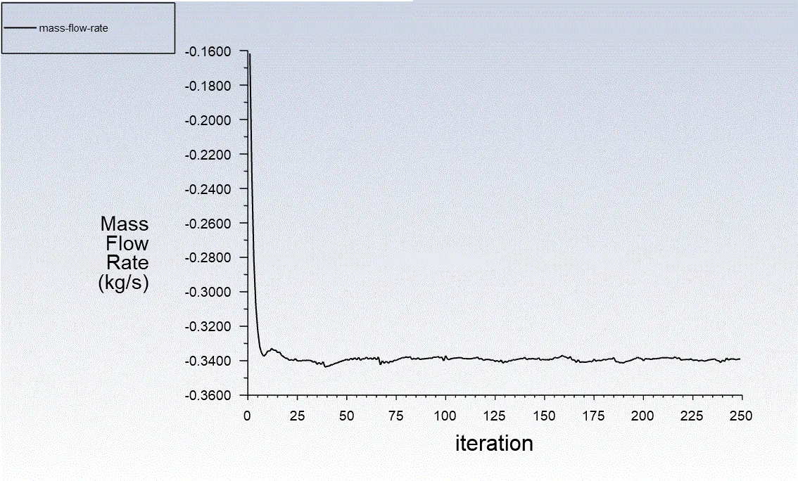
40 mm case:
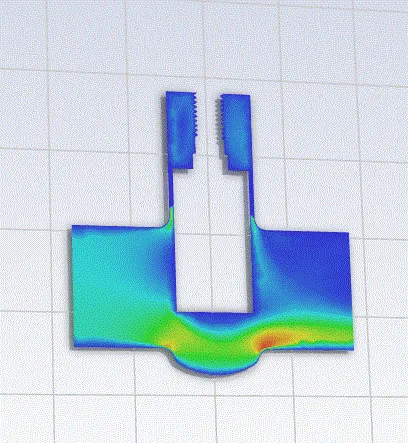
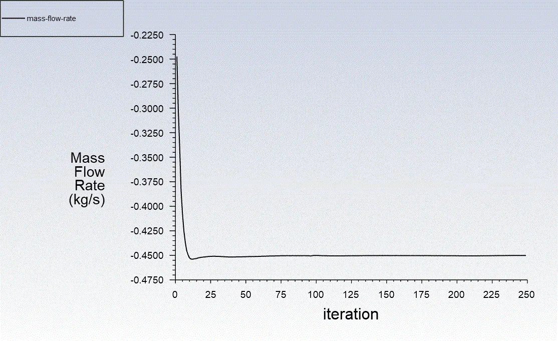
50 mm case:
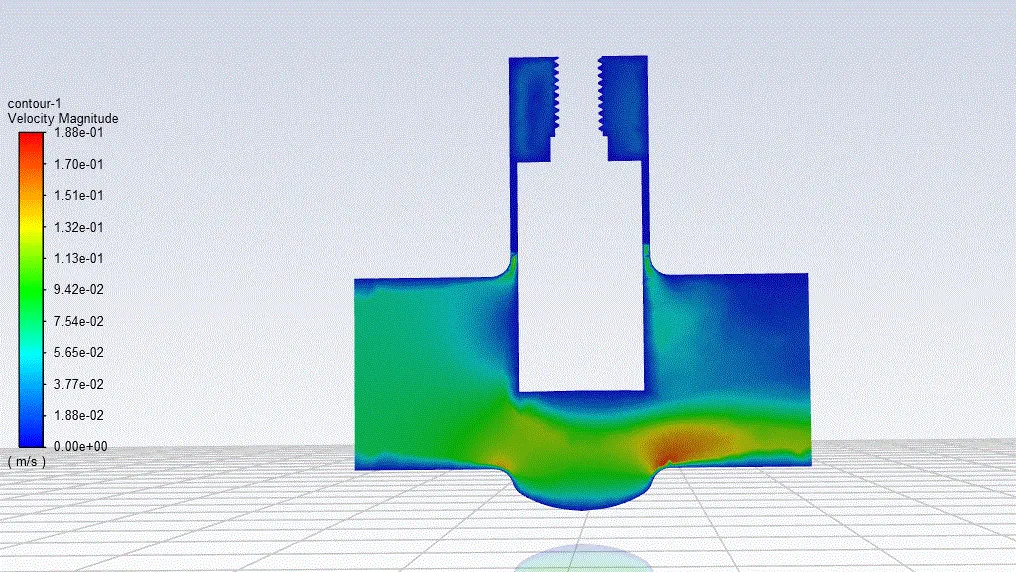
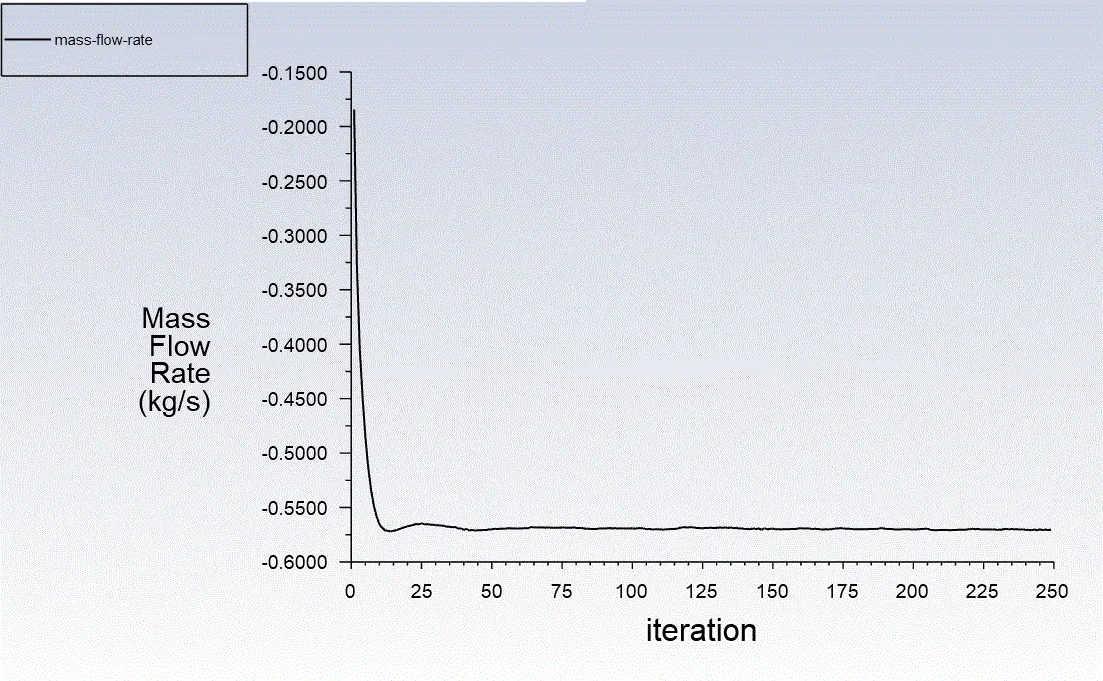
60 mm case:
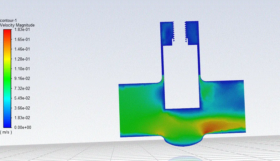
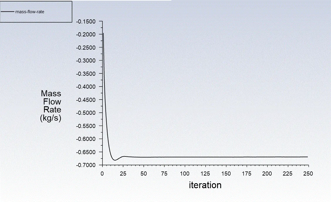
70 mm case:
The mass flow rate graph is showing some wrong results. However, on compute, console window is showing the correct value of -0.738 kg/s.
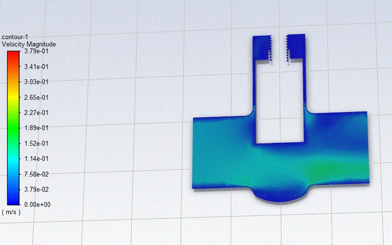
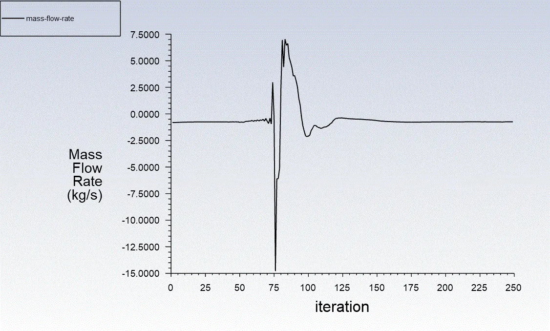
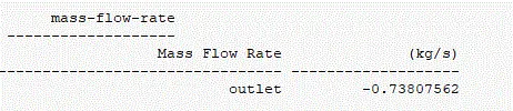
80 mm case:
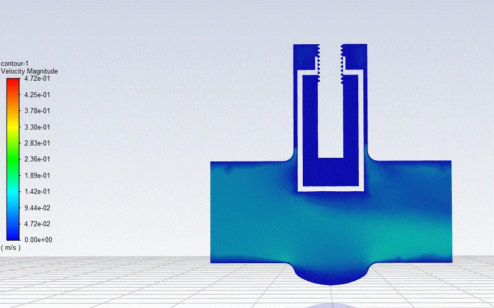
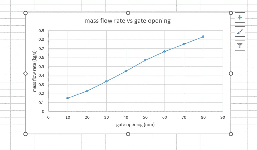
Mass flow rate for all design points
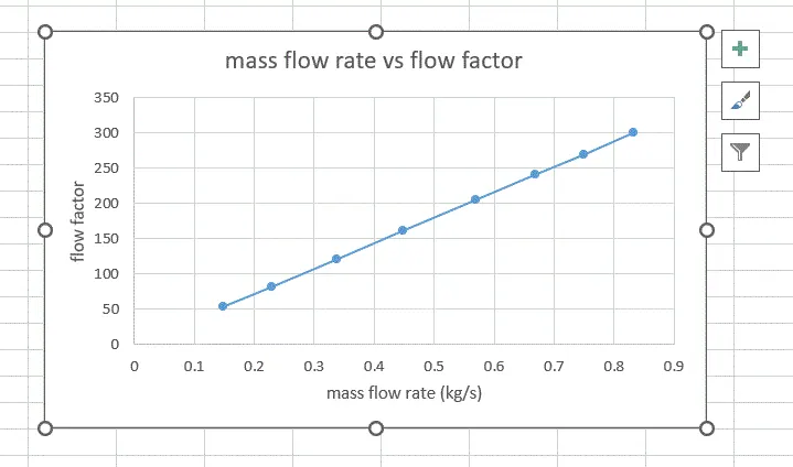
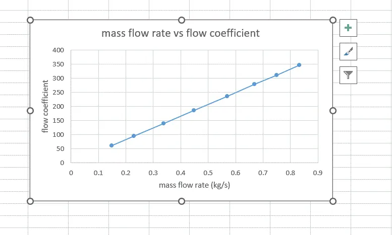
Flow coefficient and Flow factor
Conclusion
As the gate is moved up, more water can pass through gate valve and thus mass flow rate increases linearly.
Also, the flow factor and flow coefficient is found to be directly proportional to the mass flow rate or gate valve opening.
Flow factor and flow coefficient is used to decide the size of gate valve in the pipes.
By using parametric option, we can obtain the results at different parameters in single simulation. Thus, it saves the computational time.
Gaps:
Another parameter such as simulation at different inlet velocity can also be added.