Week 8 - Simulation of a backward facing step in OpenFOAM
Aim : To simulate the incompressible - laminar flow through backward facing step geometry using OpenFoam.
Procedure :
As the case is of laminar-incompressible flow - icoFoam solver was selected for simulation.
1. Geometry is made, as given in question using proper vertices. (200 along x and 20 along y)
2. Nodes were divided as per the question.
3. Boundary vortex was selected as per right hand thumb rule.
4. Boundary condition was selected as inlet, outlet,upperwall, lowerwall, front and back .
blockMeshDict file as follows:
/*--------------------------------*- C++ -*----------------------------------*\
  =========                 |
  \\      /  F ield         | OpenFOAM: The Open Source CFD Toolbox
   \\    /   O peration     | Website:  https://openfoam.org
    \\  /    A nd           | Version:  8
     \\/     M anipulation  |
\*---------------------------------------------------------------------------*/
FoamFile
{
    version     2.0;
    format      ascii;
    class       dictionary;
    object      blockMeshDict;
}
// * * * * * * * * * * * * * * * * * * * * * * * * * * * * * * * * * * * * * //

convertToMeters 1;

vertices
(
    (0 0 0) // 0
    (0.08 0 0) // 1
    (0.08 0.005 0) // 2
    (0 0.005 0) // 3
    (0 0 0.001) // 4
    (0.08 0 0.001) // 5
    (0.08 0.005 0.001) // 6
    (0 0.005 0.001) // 7
    (0.08 0.01 0) // 8
    (0 0.01 0) // 9
    (0.08 0.01 0.001) // 10
    (0 0.01 0.001) // 11
    (0.2 0.005 0) // 12
    (0.2 0.01 0) // 13
    (0.2 0.005 0.001) // 14
    (0.2 0.01 0.001) // 15
    (0.2 0 0) // 16
    (0.2 0 0.001) // 17
    (0.08 -0.01 0) // 18
    (0.2 -0.01 0) // 19
    (0.08 -0.01 0.001) // 20
    (0.2 -0.01 0.001) // 21
);

blocks
(
    hex (0 1 2 3 4 5 6 7) (80 10 1) simpleGrading (1 1 1)
    hex (3 2 8 9 7 6 10 11) (80 10 1) simpleGrading (1 1 1)
    hex (2 12 13 8 6 14 15 10) (120 10 1) simpleGrading (1 1 1)
    hex (1 16 12 2 5 17 14 6) (120 10 1) simpleGrading (1 1 1)
    hex (18 19 16 1 20 21 17 5) (120 20 1) simpleGrading (1 1 1)
);

edges
(
);

boundary
(
    inlet
    {
        type patch;
        faces
        (
            (11 9 3 7)
            (7 3 0 4)
        );
    }
    outlet
    {
        type patch;
        faces
        (
            (12 13 15 14)
            (16 12 14 17)
            (19 16 17 21)
        );
    }
    upperWall
    {
        type wall;
        faces
        (
            (8 9 11 10)
            (13 8 10 15)
        );
    }
    lowerWall
    {
        type wall;
        faces
        (
            (0 1 5 4)
            (18 19 21 20)
            (1 18 20 5)
        );
    }
    frontAndBack
    {
        type empty;
        faces
        (
            (10 11 7 6)
            (6 7 4 5)
            (15 10 6 14)
            (14 6 5 17)
            (17 5 20 21)
            (9 8 2 3)
            (8 13 12 2)
            (3 2 1 0)
            (2 12 16 1)
            (1 16 19 18)
        );
    }
);

mergePatchPairs
(
);
// ************************************************************************* //
5. blockMesh was done.
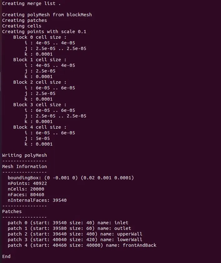
6. After blockMesh, initial conditions of P,U were edited as per the question. (viscosity of water was used)
code of p file as follows:
/*--------------------------------*- C++ -*----------------------------------*\
  =========                 |
  \\      /  F ield         | OpenFOAM: The Open Source CFD Toolbox
   \\    /   O peration     | Website:  https://openfoam.org
    \\  /    A nd           | Version:  8
     \\/     M anipulation  |
\*---------------------------------------------------------------------------*/
FoamFile
{
    version     2.0;
    format      ascii;
    class       volScalarField;
    object      p;
}
// * * * * * * * * * * * * * * * * * * * * * * * * * * * * * * * * * * * * * //

dimensions      [0 2 -2 0 0 0 0];

internalField   uniform 0;

boundaryField
{
    inlet
    {
        type            zeroGradient;

    }
    outlet
    {
        type            fixedValue;
        value           uniform 0;
    }
    upperWall
    {
        type            zeroGradient;
    }
    lowerWall
    {
        type            zeroGradient;
    }
    frontAndBack
    {
        type            empty;
    }
}
// ************************************************************************* //
code of U file as follows:
/*--------------------------------*- C++ -*----------------------------------*\
  =========                 |
  \\      /  F ield         | OpenFOAM: The Open Source CFD Toolbox
   \\    /   O peration     | Website:  https://openfoam.org
    \\  /    A nd           | Version:  8
     \\/     M anipulation  |
\*---------------------------------------------------------------------------*/
FoamFile
{
    version     2.0;
    format      ascii;
    class       volVectorField;
    object      U;
}
// * * * * * * * * * * * * * * * * * * * * * * * * * * * * * * * * * * * * * //

dimensions      [0 1 -1 0 0 0 0];

internalField   uniform (0 0 0);

boundaryField
{
    inlet
    {
        type            fixedValue;
        value           uniform (0.1 0 0);
    }
    outlet
    {
        type            zeroGradient;
    }
    upperWall
    {
        type            noSlip;
    }
    lowerWall
    {
        type            noSlip;
    }
    frontAndBack
    {
        type            empty;
    }
}
// ************************************************************************* //
dt is kept 0.001 sec and velocity is 0.1 m/s, end time was kept 4 sec. it is because the flow will take 2 sec to completely flow across the length and 4 sec means steady state has reached.
code of controlDict file as follows:
/*--------------------------------*- C++ -*----------------------------------*\
  =========                 |
  \\      /  F ield         | OpenFOAM: The Open Source CFD Toolbox
   \\    /   O peration     | Website:  https://openfoam.org
    \\  /    A nd           | Version:  8
     \\/     M anipulation  |
\*---------------------------------------------------------------------------*/
FoamFile
{
    version     2.0;
    format      ascii;
    class       dictionary;
    location    "system";
    object      controlDict;
}
// * * * * * * * * * * * * * * * * * * * * * * * * * * * * * * * * * * * * * //

application     icoFoam;

startFrom       startTime;

startTime       0;

stopAt          endTime;

endTime         4;

deltaT          0.001;

writeControl    timeStep;

writeInterval   20;

purgeWrite      0;

writeFormat     ascii;

writePrecision  6;

writeCompression off;

timeFormat      general;

timePrecision   6;

runTimeModifiable true;


// ************************************************************************* //
Code of Transport Properties file is as follows: (kinematic viscosity of water was used)
/*--------------------------------*- C++ -*----------------------------------*\
  =========                 |
  \\      /  F ield         | OpenFOAM: The Open Source CFD Toolbox
   \\    /   O peration     | Website:  https://openfoam.org
    \\  /    A nd           | Version:  8
     \\/     M anipulation  |
\*---------------------------------------------------------------------------*/
FoamFile
{
    version     2.0;
    format      ascii;
    class       dictionary;
    location    "constant";
    object      transportProperties;
}
// * * * * * * * * * * * * * * * * * * * * * * * * * * * * * * * * * * * * * //

nu              [0 2 -1 0 0 0 0] 8.9e-7;


// ************************************************************************* //
7. simulation were done using icoFoam solver.
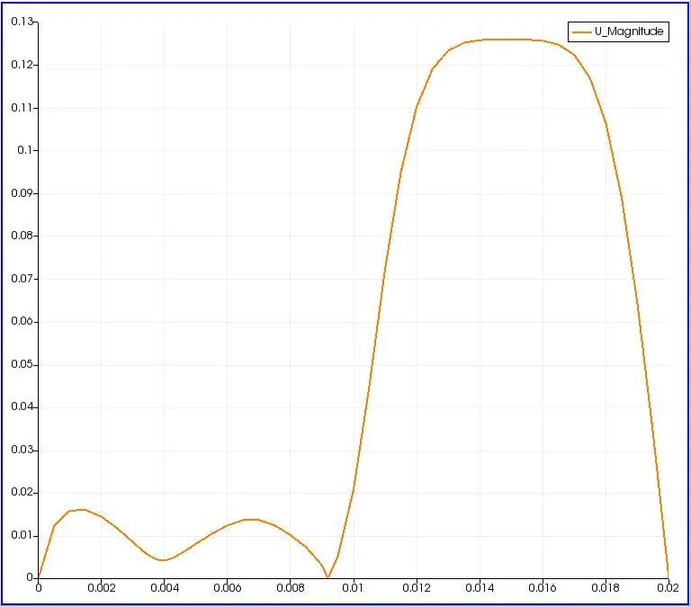
8. velocity graph were drawn from paraview.
paraview results are as follows:
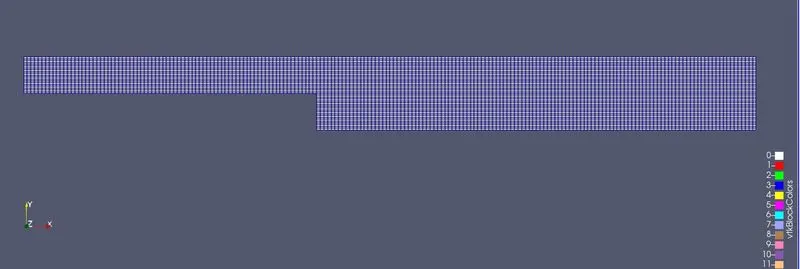
this case with uniform grading.
the velocity graph is as follows:
Case 2: (with grading factor of 0.2)
1. everything is same except the simple grading in blockMeshDict file.
blockMeshDict file is as follows:
/*--------------------------------*- C++ -*----------------------------------*\
  =========                 |
  \\      /  F ield         | OpenFOAM: The Open Source CFD Toolbox
   \\    /   O peration     | Website:  https://openfoam.org
    \\  /    A nd           | Version:  8
     \\/     M anipulation  |
\*---------------------------------------------------------------------------*/
FoamFile
{
    version     2.0;
    format      ascii;
    class       dictionary;
    object      blockMeshDict;
}
// * * * * * * * * * * * * * * * * * * * * * * * * * * * * * * * * * * * * * //

convertToMeters 1;

vertices
(
    (0 0 0) // 0
    (0.08 0 0) // 1
    (0.08 0.005 0) // 2
    (0 0.005 0) // 3
    (0 0 0.001) // 4
    (0.08 0 0.001) // 5
    (0.08 0.005 0.001) // 6
    (0 0.005 0.001) // 7
    (0.08 0.01 0) // 8
    (0 0.01 0) // 9
    (0.08 0.01 0.001) // 10
    (0 0.01 0.001) // 11
    (0.2 0.005 0) // 12
    (0.2 0.01 0) // 13
    (0.2 0.005 0.001) // 14
    (0.2 0.01 0.001) // 15
    (0.2 0 0) // 16
    (0.2 0 0.001) // 17
    (0.08 -0.01 0) // 18
    (0.2 -0.01 0) // 19
    (0.08 -0.01 0.001) // 20
    (0.2 -0.01 0.001) // 21
);

blocks
(
    hex (0 1 2 3 4 5 6 7) (80 10 1) simpleGrading (1 5 1)
    hex (3 2 8 9 7 6 10 11) (80 10 1) simpleGrading (1 0.2 1)
    hex (2 12 13 8 6 14 15 10) (120 10 1) simpleGrading (10 0.2 1)
    hex (1 16 12 2 5 17 14 6) (120 10 1) simpleGrading (10 5 1)
    hex (18 19 16 1 20 21 17 5) (120 20 1) simpleGrading (10 5 1)
);

edges
(
);

boundary
(
    inlet
    {
        type patch;
        faces
        (
            (11 9 3 7)
            (7 3 0 4)
        );
    }
    outlet
    {
        type patch;
        faces
        (
            (12 13 15 14)
            (16 12 14 17)
            (19 16 17 21)
        );
    }
    upperWall
    {
        type wall;
        faces
        (
            (8 9 11 10)
            (13 8 10 15)
        );
    }
    lowerWall
    {
        type wall;
        faces
        (
            (0 1 5 4)
            (18 19 21 20)
            (1 18 20 5)
        );
    }
    frontAndBack
    {
        type empty;
        faces
        (
            (10 11 7 6)
            (6 7 4 5)
            (15 10 6 14)
            (14 6 5 17)
            (17 5 20 21)
            (9 8 2 3)
            (8 13 12 2)
            (3 2 1 0)
            (2 12 16 1)
            (1 16 19 18)
        );
    }
);

mergePatchPairs
(
);
// ************************************************************************* //
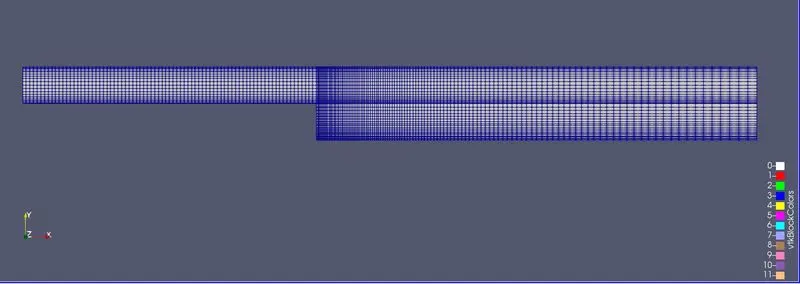
paraFoam results are:
velocity diagram is as follows:
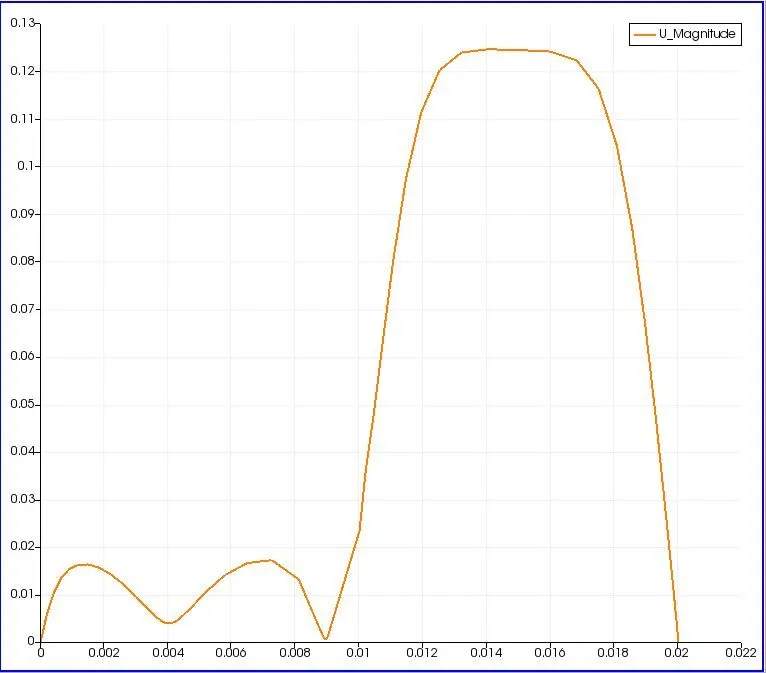
The velocity graph looks more acurate with grading. Finer the meshing, results will be more accurate. To capture the boundary conditions more effectively, Grading is required. The difference can be felt at inlet region as the width is less, thus more finer mesh is required to capture the exact velocity.