Week 9 - Parametric study on Gate valve.
Week 9 - Parametric study on Gate valve
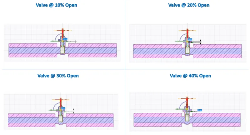
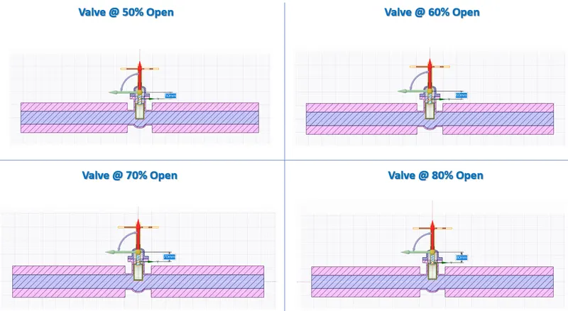
Aim: To perform a parametric study on the gate valve simulation by setting the opening from 10 % to 80%.
Objective:
- Obtain the mass flow rates at the outlet for each design point.
- Calculate the flow coefficient and flow factor for each opening and plot the graph.
- Discuss the results of the mass flow rate and flow coefficient.
Theory:
A valve is a device that regulates, controls, or directs the flow of a fluid by opening, closing, or partially obstructing fluid flow.
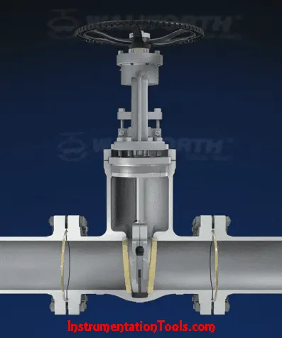
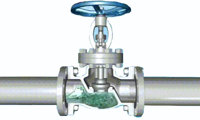
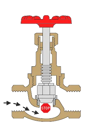
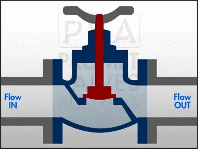
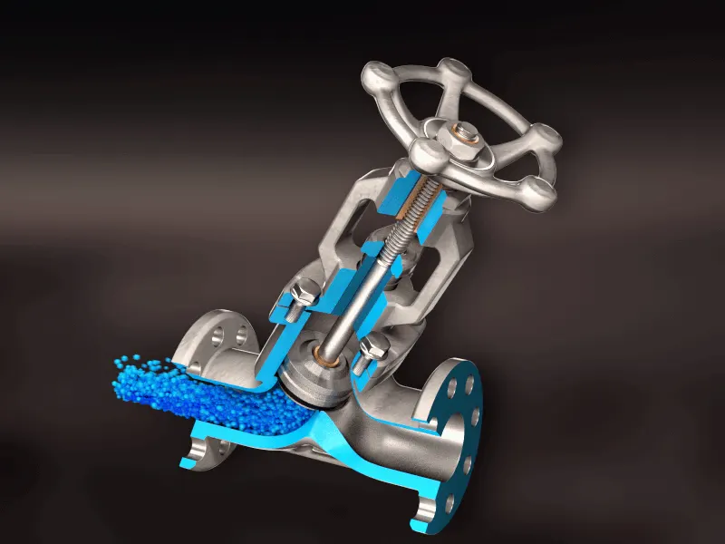
Types of Valves:
- Gate Valve
- Globe Valve
- Check Valve
- Plug Valve
- Ball Valve
- Butterfly Valve
- Needle Valve
- Pinch Valve
- Pressure Relief Valve
Gate Valve:
A gate valve can be defined as a type of valve that uses a gate or wedge-type disk, and the disk moves perpendicular to flow to start or stop the fluid flow in piping.
A gate valve is the most common type of valve used in any process plant. It is a linear motion valve used to start or stop fluid flow.
When the gate valve is fully open, the disk of a gate valve is completely removed from the flow. Therefore virtually no resistance to flow. Due to this, very little pressure drops when fluid passes through a gate valve.
360° surface contact is required between the disk and seats when the valve is fully closed to achieve proper sealing.
Gate valves should not be used for regulation or throttling of flow because accurate control is not possible. The high velocity of the flow in the partially open valve may cause erosion of the disc and seating surfaces and also creates vibration and noise.
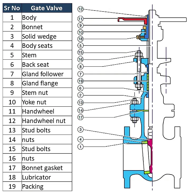
Types of Gate valves:
There are three ways to classify the gate valve.
- Types of Disk
- Solid taper wedge
- Flexible wedge
- Split wedge or Parallel disks Valve
- Types of Body Bonnet Joint
- Screwed Bonnet
- Bolted-Bonnet
- Welded-Bonnet
- Pressure-Seal Bonnet
- Types of Stem Movement
- Rising Stem or OS & Y Type (Outside Stem and Screw Type)
- Non-rising Stem type
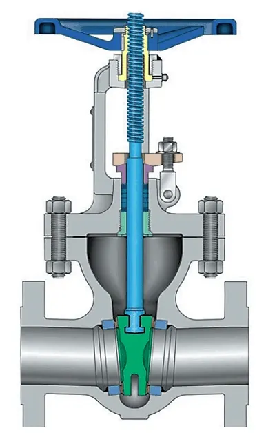
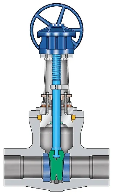
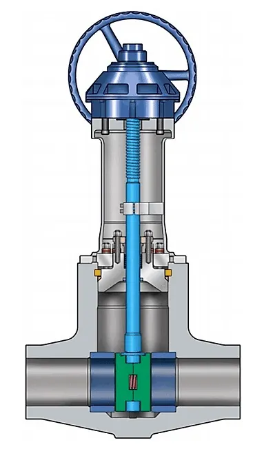
Solid Wedge Gate Valve Flexible Wedge Gate Valve Split Wedge Parallel disks Gate Valve
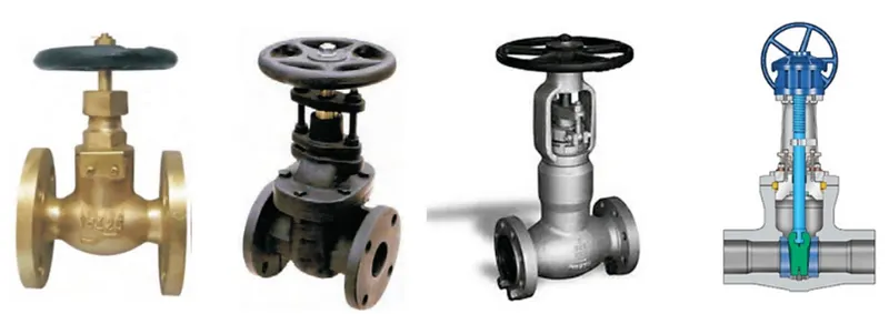
Screwed Bonnet Bolted-Bonnet Welded-Bonnet Pressure-Seal Bonnet
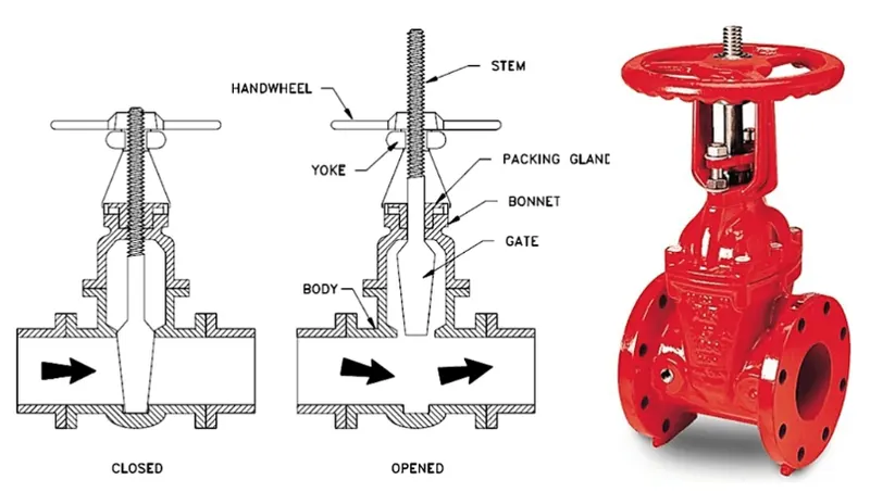
Rising Stem or OS & Y Type (Outside Stem and Screw Type)
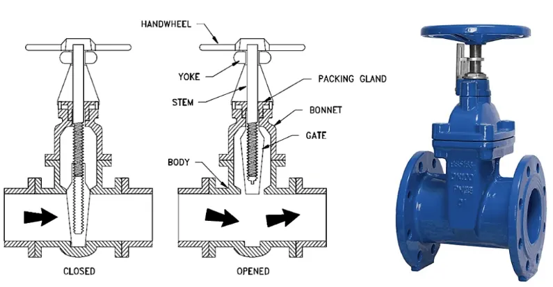
Non-rising Stem Gate Valve or Insider Valve
Gate Valve Applications
- Gate valves are used in almost all fluid services such as air, fuel gas, feedwater, steam, lube oil, hydrocarbon, and almost any services.
- Some special gate valve is used in slurry and powder product also, such as knife gate valve.
Advantages of Gate Valve
- Gate valve provides good shutoff
- Pressure drop during operation is very less
- Most of the gate valves can be used as bi-directional
- They are suitable for high-pressure and temperature applications and require less maintenance
Disadvantages of Gate Valve
- It cannot be used to control the flow.
- A gate valve is slow in operation. Opening and closing take time which is good also as it reduces the chance of hammering.
- When partially open, it creates vibration and noise.
- Repairs, such as lapping and grinding of seats are more difficult due to limited access.
Analytical Validation:
In the principle of conservation of energy, we have a liquid flowing through an orifice, the square of the fluid velocity is directly proportional to the pressure differential across the orifice and inversely proportional to the specific gravity of the fluid.
The greater the pressure difference, the higher the velocity, and the greater the density, the lower the velocity.
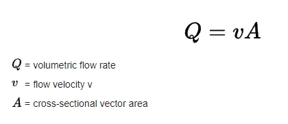
The Volume flow rate for liquids can be calculated by
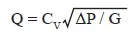
Bu considering the Proportionality relationship with the Volumetric flow rate, Energy losses due to friction and turbulence, and varying discharge coefficients for various types of orifices Basic Volumetric equation can be rewritten as
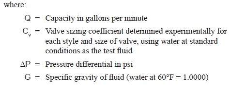
From the above equation, Flow Coefficient can be determined as below.
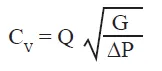
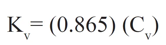
The flow rate is approximately 0.865 times the flow coefficient (Proven by experimental validation)
Simulation:
Parametric Model Setup:
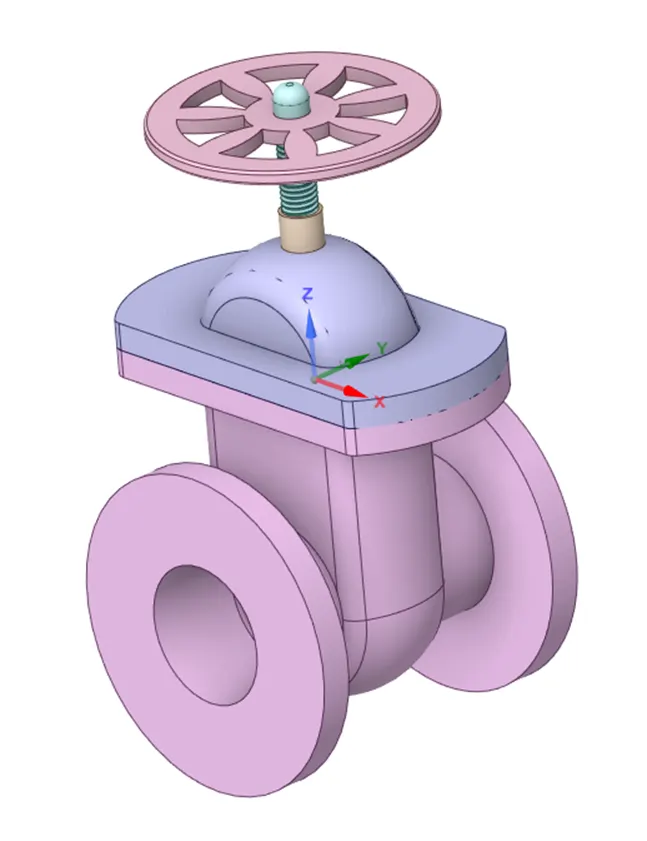
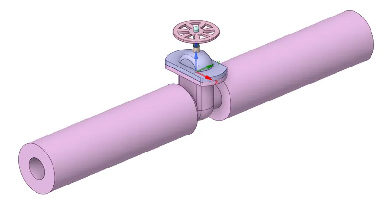
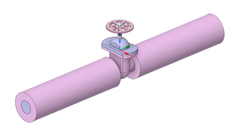
Given Model Modified Valve for flow enhancement Fluid Generated for the valve model
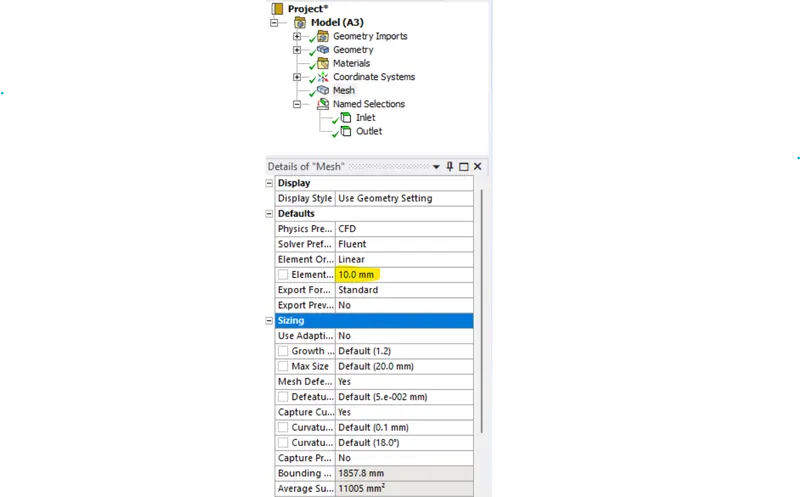
Meshing:

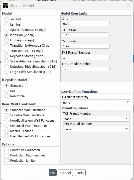
Simulation Setup:
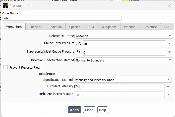
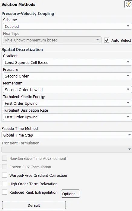
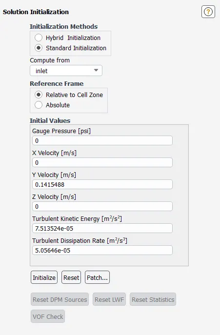
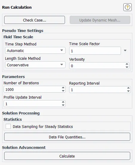
Results:
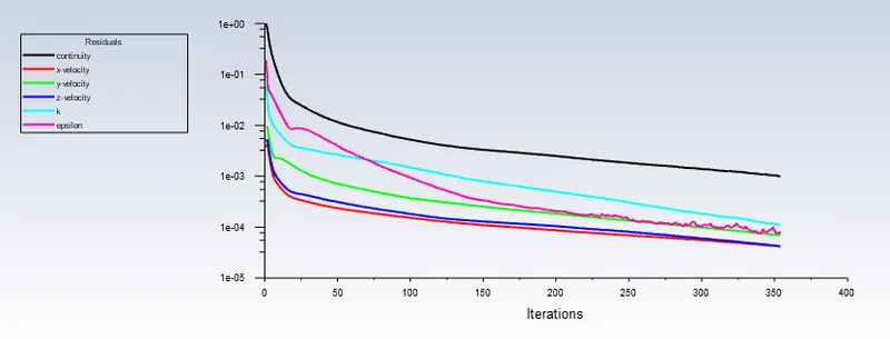
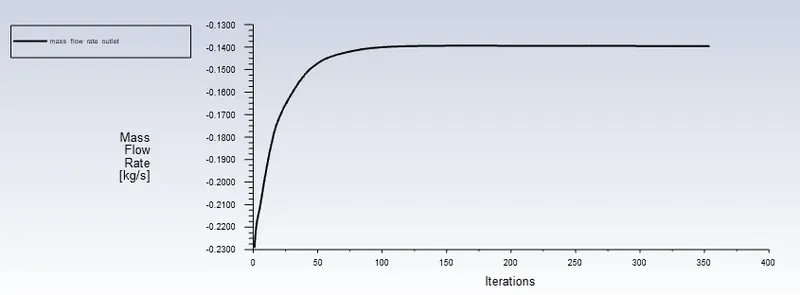
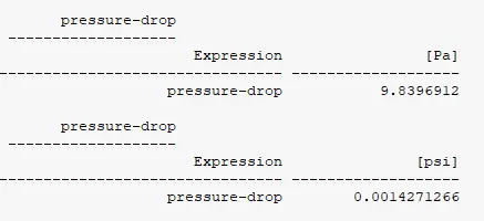
Pressure Contour (case-8)
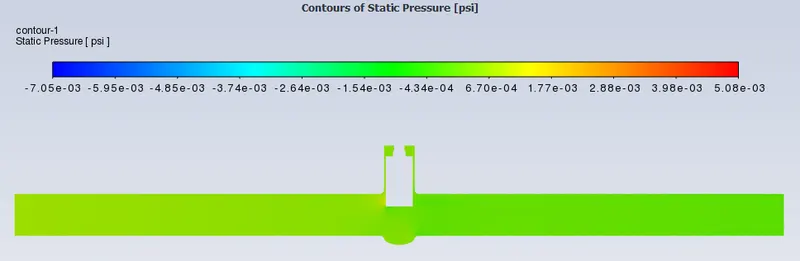
Velocity Contour (case-8)
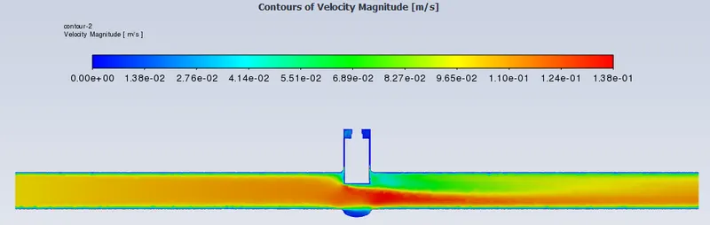
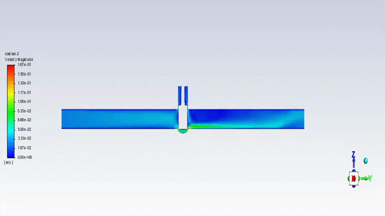
The same steps are followed for all other variations.
Conclusion:
From the below table, we can conclude that by lifting the valve gate disc flow rate gradually increases.

A variation in the lift of the gate disc is achieved by using a parametric study, by this method we can reduce time.
References:
1. https://hardhatengineer.com/gate-valve-types-parts/
2. https://engineeringlearn.com/gate-valve-types-and-parts/
3. https://www.avkvalves.eu/en/insights/product-insights/gate-valves/what-is-a-gate-valve