Week 9 - Parametric study on Gate valve.
Aim: To perform a parametric study on a gate valve by setting the opening from 10% to 80%.
Theory:
Valves are the devices used to direct, control or regulate the flow of a fluid by opening, closing or partially obstructing the flow passage. The valves classification can be summarized with the following picture:
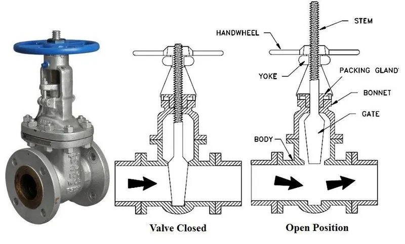
valve classification Gate Valve
Gate Valve:
A gate valve is a linear motion valve used to start or stop the fluid flow; however, it does not regulate or throttle flow. The name gate is derived from the appearance of the disk in the flow stream. The disk of a gate valve is completely removed from the flow stream when the valve is fully open. Hence, there is little pressure drop across an open gate valve. When the valve is fully closed, a disk-to-seal ring contact surface exists for 360°, and good sealing is provided. A gate valve can be used for various fluids and provides a tight seal when closed.
Valve Flow Coefficient (Cv) is the flow capability of a control valve at fully open conditions relative to the pressure drop across the valve. It is defined as the volume of water (GPM in the US) at 60°F that will flow through a fully open valve with a pressure differential of 1 psi across the valve. Mathematically,
Cv=Q×√SGΔP
where,
Q is flow rate in Gallons per minute.
SG is specific gravity of the fluid
ΔP is change in pressure in psi.
Flow factor is (Kv) is metric equivalent of Valve Flow Coefficient and is defined mathematically as Kv=0.864Cv.
Valve coefficient or valve factor helps us to choose a suitable size of the valve.
Case Setup:
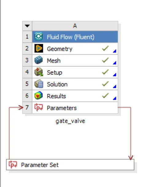
The case is setup in project schematic window with fluent analysis system from toolbox window.
The geometry is imported in space claim. The volume is extracted and movement of gate disc in upward direction is set up as input parameter. We also need to increase the inlet and outlet pipe length in order to get developed flow at the inlet off the gate valve and downstream of gate valve to get flow parameter values like pressure and velocity which are consistent with the overall flow condition.
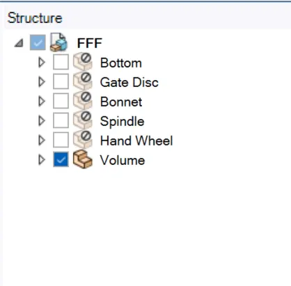
Only extracted volume is enabled for the simulation. Rest of all bodies are suppressed for physics.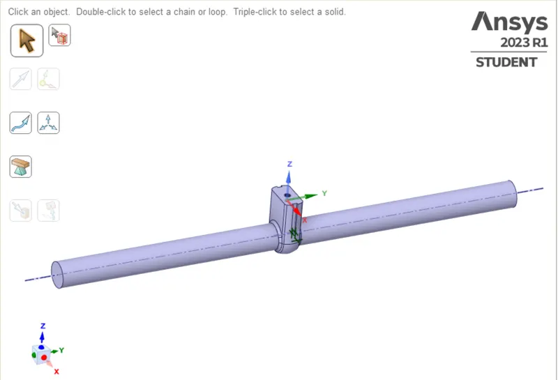
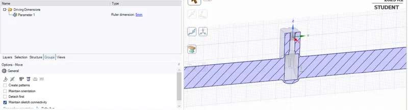
Default Mesh is selected for this case.
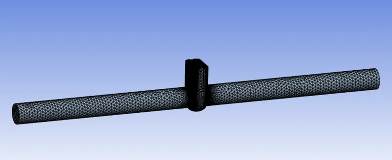
Following options are selected for setting the case in fluent:
| Solver Type | Pressure Based |
| Time | Steady |
| Gravity | Enabled |
| Viscous Model | k−ε Realizable |
| Near wall treatment | Scalable Wall Functions |
| Fluid | Water |
| Inlet Boundary Condition | Pressure-Inlet (10 Pa gauge) |
| Outlet Boundary Condition | Pressure-outlet (0 gauge) |
| Initialization | Hybrid |
| Iterations | 200 |
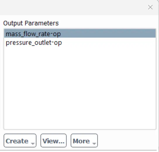
n Report-definition reports for mass flow rate and pressure just before outlet section are set up with both selected as output parameter.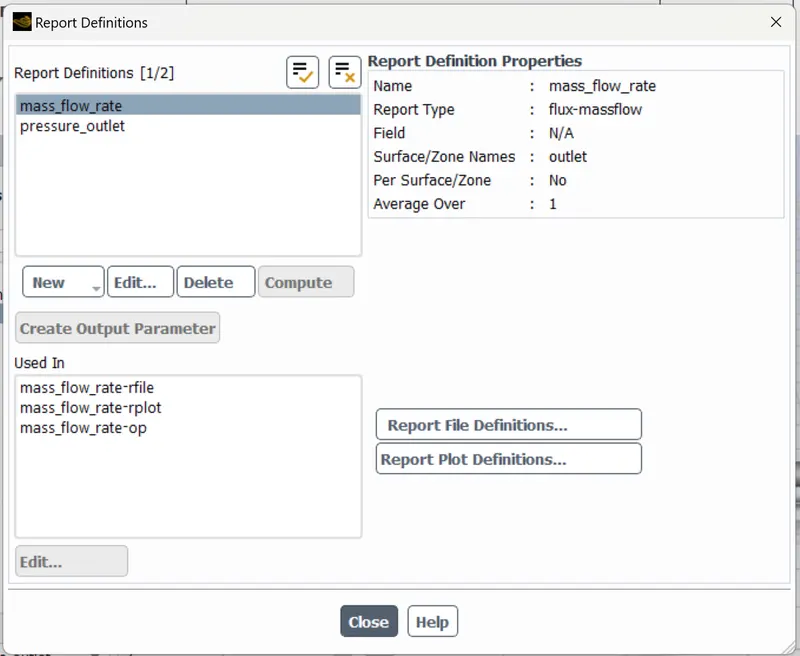
Results:
The case was solved for various values of gate disc opening and following plots were obtained-
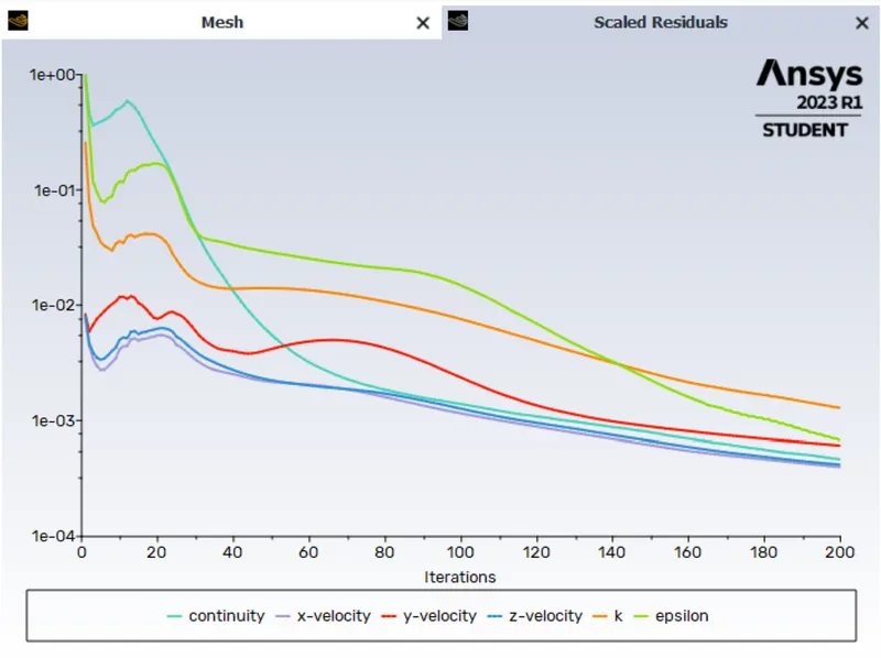
The above scaled residue plot is a general plot for all the cases. From scaled residue plot it is easily inferred that solution is converged.
Opening 10% (10 mm):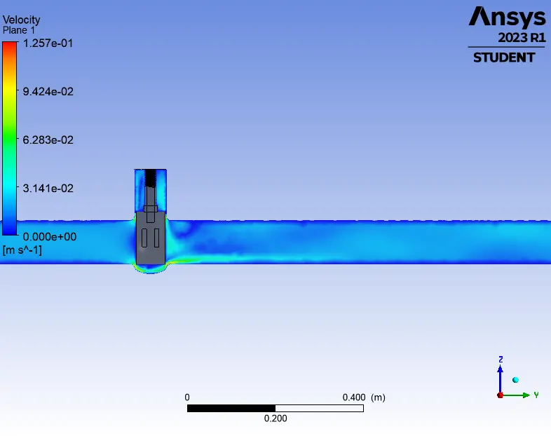
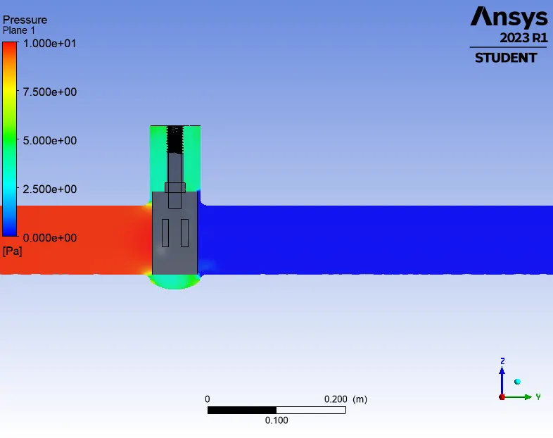
velocity profile (10 mm) pressure profile (10 mm)
Opening 20% (20 mm):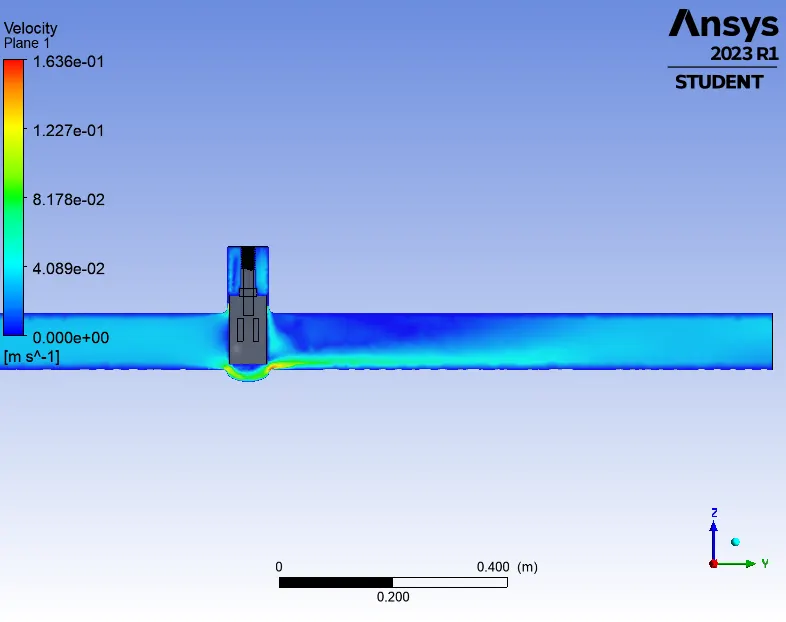
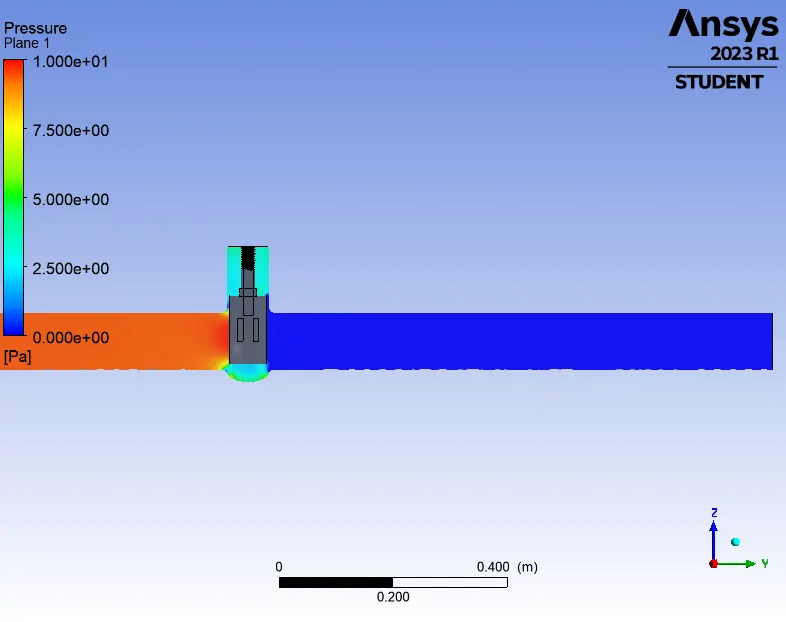
velocity profile (20 mm) pressure profile (20 mm)
Opening 45% (45 mm):
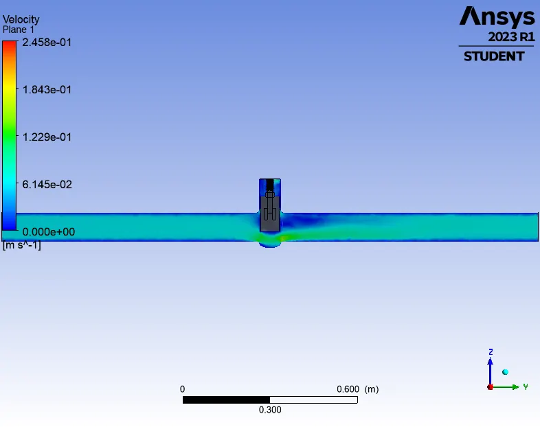
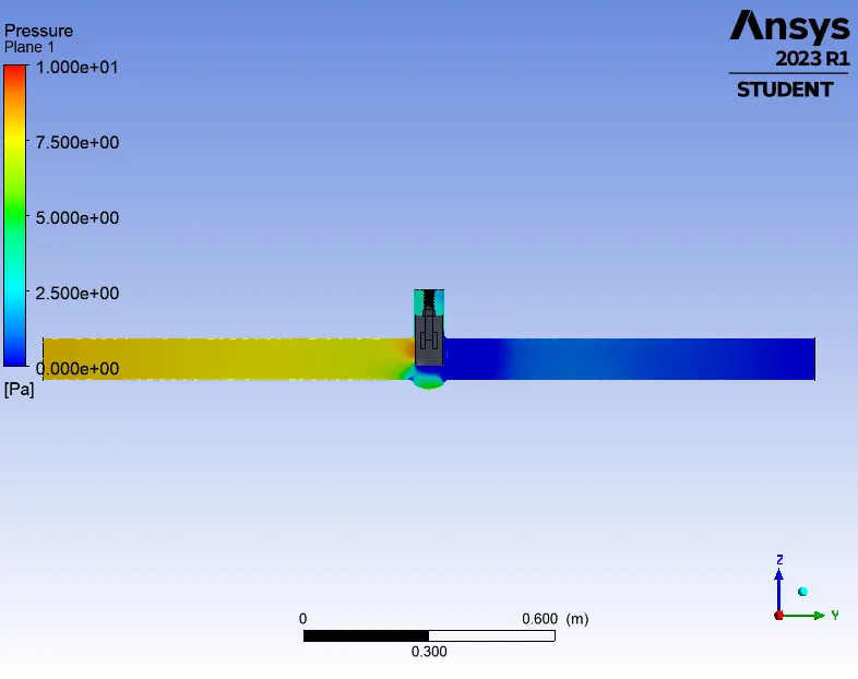
velocity profile (45 mm) pressure profile (45 mm)
Opening of 60% (60 mm):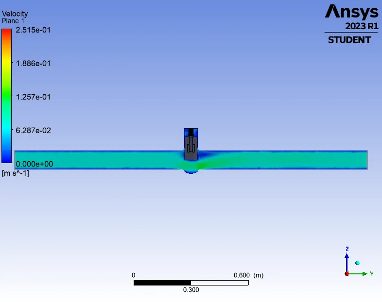
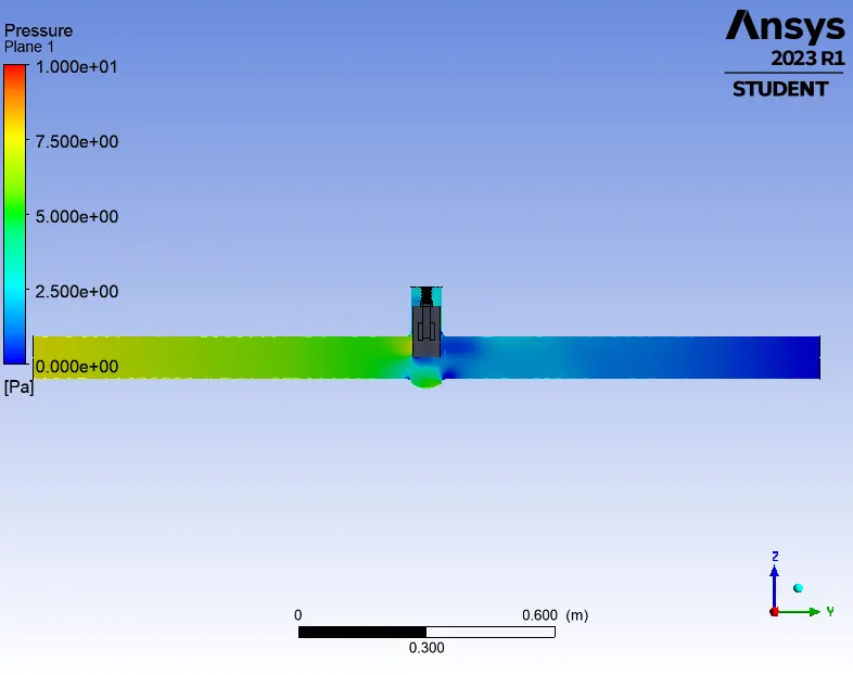
velocity profile (60mm) pressure profile (60 mm)
Opening of 80% (80 mm):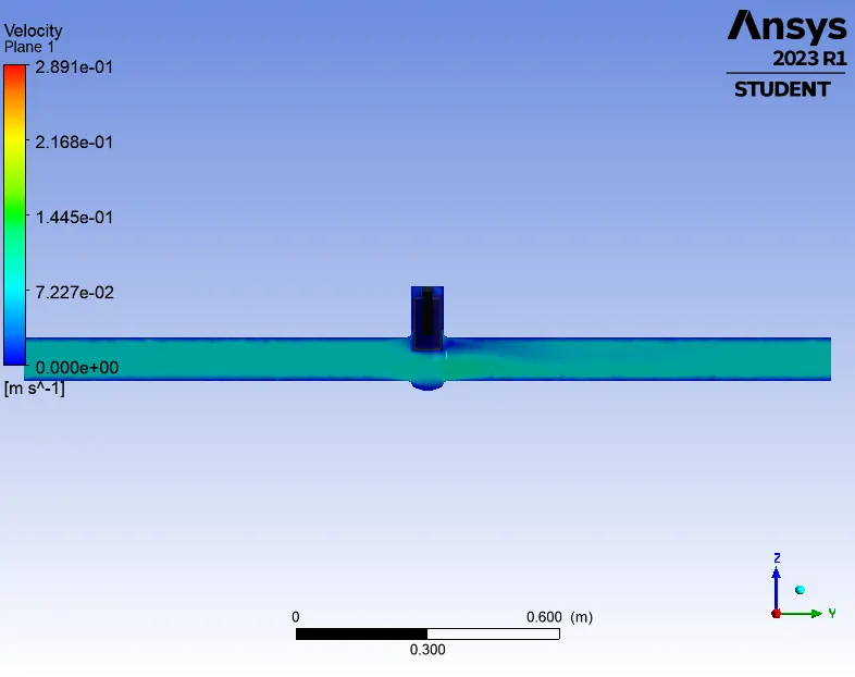
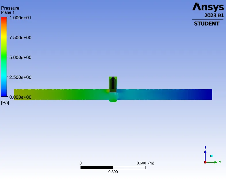
velocity profile (80mm) pressure profile (80 mm)
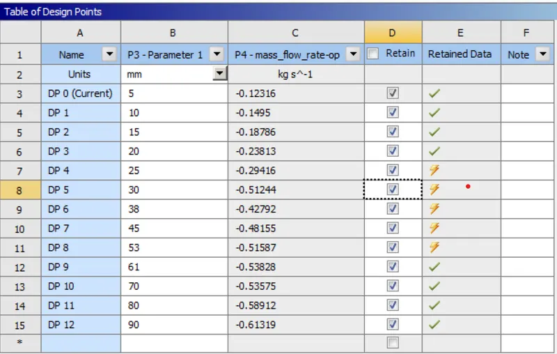
The above results are plotted to understands the affect on wall opening on mass flo rate and pressure downstream: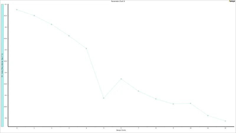
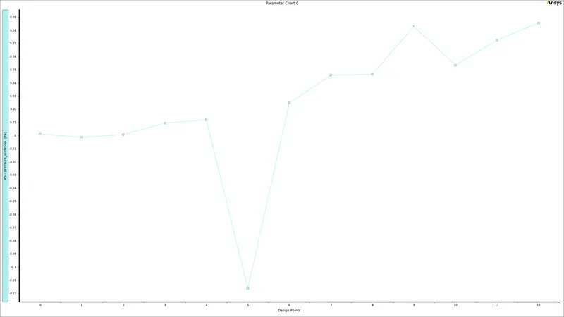
opening vs negative of mass flow rate opening vs pressure just before outlet
Conclusions:
- The Flow Coefficients for all the design points are as follows:
Design Points (in mm) Valve Flow Coefficient (Cv) Flow Factor Kv 5 69.25 59.83 10 84.05 72.65 15 105.67 91.29 20 133.96 115.74 25 165.50 143.00 30 286.48 247.52 38 240.91 208.15 45 271.39 234.50 53 290.75 251.20 61 303.93 262.60 70 302.10 261.00 80 332.46 287.25
The trend followed by Valve Flow Coefficient or Flow Factor are consistent with the physical findings i.e: the flow coefficient values are increasing with the increase in valve opening. - Based on these values appropriate valve size must be choosen. Accepted practice is the desired Cvshould be between 20-80% valve opening of the valve.
- Accepted practice is, a valve is chosen such that the desired Cvis between the valve Cvcorresponding to 20-80% of valve opening.
- The velocity plot shows velocity to be maximum below the gate. The reason being the fluid being incompressible and narrow passage below the valve the flow leading to acceleration of the flow.
- Care must be taken while choosing opening of valve opening. The difference between succesive points should not be large else results might be inaccurate.