Week 9 - Parametric study on Gate valve.
PARAMETRIC STUDY ON GATE VALVE
Aim : To perform a parametric study on the gate valve simulation by setting the opening from 10% to 80%
Objective :
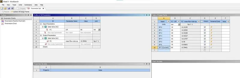
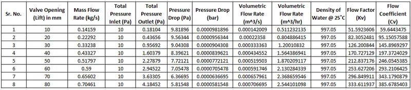
- Obtain the mass flow rates at the outlet for each design point.
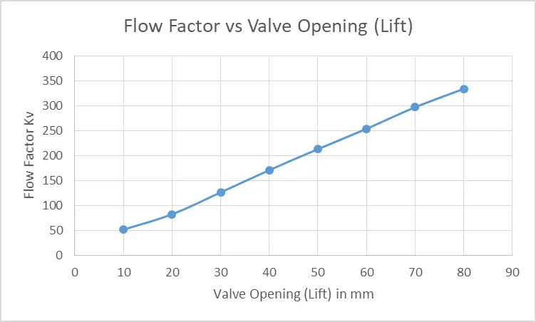
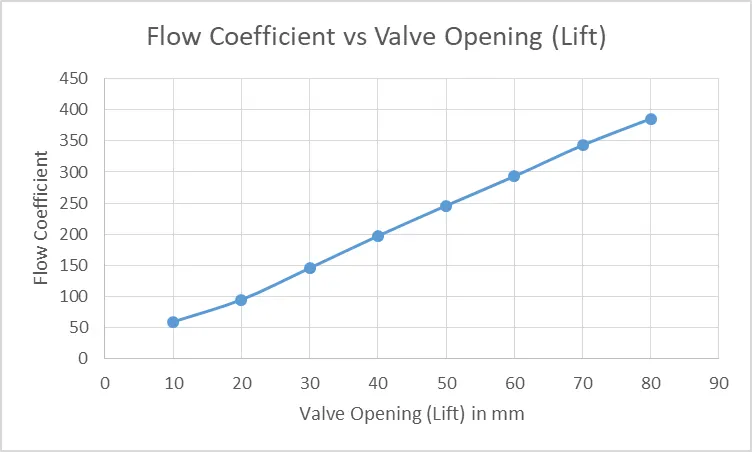
- Calculate the flow coefficient and flow factor for each opening and plot the graph.
- Discuss the results of the mass flow rate and flow coefficient.
GATE VALVE
A gate valve, also known as a sluice valve, is a valve that opens by lifting a barrier (gate) out of the path of the fluid. Gate valves require very little space along the pipe axis and hardly restrict the flow of fluid when the gate is fully opened. The gate faces can be parallel but are most commonly wedge-shaped (in order to be able to apply pressure on the sealing surface).
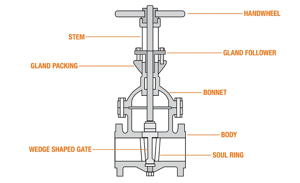
Gate Wall always opens in the perpendicular direction of the flow of fluid. It is only used to stop or restart the flow of fluid.
This cannot be used as a regulator, because in the starting when it is allowed to open it creates a lot of noise and vibration which creates damage in the disc so that it starts leaking. That’s why did it is fully opened or closed.
The gate valve has two stems rising and non-rising stem.
Stem: A rod that is connected by a disc from one end and the other side connected to the hand wheel.
In the rising stem, when you start rotating handwheels, as the valve opens you can see the rod coming out, and it closes the road goes down. This means you can see the portion of the walls.
But in a non-rising stem, you are unable to see the stem physically. You can see the portion of a wall with the help of an indicator. It is also called Indister screw wall. Mostly used underground when there is a shortage of space.
Gate valve Parts or Construction:
The following construction or Parts of Gate Valve:
- Body
- Bonnet
- Disc
- Seat
- Stem and
- Manual actuators
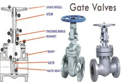
Body:
The valve body is the main pressure-retaining part, that also holds other parts named as disc and stem.
This also provides passage to flow from the valve, its end connection is piping this end can be but welding type, threaded, and many more depends upon the size and pressure of the piping system.
The valve body can be cast, forge in different materials such as cast steel, stainless steel, and alloy steel depend upon the requirement.
Bonnet:
It is the second pressure-retaining part of the valve. It is also called a cover. We can connect it with the system by bolting, welding, or threading to create a valve enclosure.
In case of the gate, stop, diaphragm wall it has the opening so that the valve stream and pass through it. Bonded provides access to valve internals during maintenance.
Disc:
This is is the part that allows throttles or stops flow on its position. In the case of a plug or ball valve, the disk is called a plug or ball.
A disc is seated against the stationary wall seat or seats when the wall is in the closed position.
It can be moved away from the valve seat by the motion of the valve string which the exception of the check valve and safety relief valve in which the disc is moved away from its seat by the fluid flow and pressure.
Seat:
This is one of the main components of the system which directly affects the leakage rate of the valve. One of the integral to valve body is made up of forged metallic rings or non-metallic rings.
All valves may have one or more seats. In the case of the globe and swing check valve, there is one seat. The gate valve has two seats, one on the upstream side and the other on the downstream side.
Multipod club and ball valves may have several seats. Depending upon the number of ports on the valve or plug.
Stem:
Stem is a forged solid rod or shaft. The valve steam transferred the required motion of the disc plug or valve for opening and closing of the valve.
The stem is connected to the valve handwheel at one end and the valve disc on the other side.
In gate for globe valve linear motion of the disk open or close the valve. While in plug, ball, butterfly valve disc is not located to open or close the valve. Note that stop check valves or check valve does not have a stem.
Manual actuators:
The actuator is a mechanism that operates the valve. It is connected to the stem and disc assemble. It may be manually operated by handwheel, manual lever, gear, chain or it can be operated through motor and solenoid.
Many other common parts of the gate valve are gland flange, stem nut, handwheel, slud nuts, bonnet gasket, and many more.
Now moving to different types of gate valve,
Types of Gate valve:
There are three ways to classify the Great valve:
- According to the types of disc
- Types of body bonnet joint and
- Types of stem movement
According to the types of disc:
There are three types of disc gate valve:
- Solid Wedge Valve
- Flexible Wedge Valve and
- Split Wedge Valve
Solid wedge:
This is one of the oldest and most common valves. It can be installed in any position and also suitable for any fluid. It can also be used in a turbulent flow.
The drawback is sometimes it starts choking because of a thermal expansion inside the pipe, because of that it is more susceptible to leakage. The thermal locking wedge got stuck between the seats due to the expansion of the metal.
Flexible wedge:
This type of disc is made in such a way it becomes flexible, by making cuts in the Periphery of the disc, it can resist thermal pressure. All the cuts are of different sizes, shapes, and depths.
This also provides some strength to it. This system also improves Seat alignment, so that it become leak tighten.
The bigger disadvantage of flexible Gates is line flood tents got collected in the disc. That leads to corrosion and also weekend the disc which is not good for the long term.
Split wedge:
It consists of two discs, that are connected with each other parallelly to this is connected with each other through the mechanical mechanism.
The disk can be in which shift as well as parallel disc type. In this thermal Blending cannot be created even after fluid gets heated.
Types of body bonnet joint:
There is a total of five types of body Bonnet joint:
- Screwed bonnet: One of the simplest designs and used for inexpensive values.
- Bolted bonnet: One of the popular designs, used in a large number of gate valves. It requires a gasket to seal the joint.
- Welded bonnet: In this disassembly is not required. Light in weight than bolted bonnet counterparts.
- Pressure seal bonnet: Extensively used for high pressure and high-temperature application. Higher body cavity more will be the force.
Types of stem movement:
- Rising stem or OS and Y type( outside stem and screw type): There is an upward and downward movement of a stem for the movement of the valve.
- Non-rising stem: There is no upward movement of the stem.
How does Gate Valve Works?
Gate valves are used in fluid pipelines to control the flow of fluid. The gate or wedge is there that controls the flow of fluid. A wedge of the gate or shape of the gate is of different shapes they may be circular or rectangular plate-shaped.
It is also termed as a disc of the gate valve. The valve is used to open or close the gate valve. When the wheel with handle is rotated then Gate or wedge moves upward or downward across the flow of any fluid.
The mechanism on which the Gate valve works: When you rotate the handle wheel clockwise then steam and get moves in the downward direction across the fluid flow, and the gate is tightly located between two seats.
So that there is no leakage of any fluid when the valve is closed completely.
When you rotate the handle Wheel in an anticlockwise direction, steam and fluid move upward at the same time across the fluid flow. The valve is opened Chrome closed position that permits the flow of fluid through the Gate valve.
Once Gate is completely opened, which permits very low resistance or no resistance to the flow of any field.
Semi opening condition is not good because it causes erosion of the gate when fluid strikes. It also creates a lot of noise and vibration at the same time.
Material used for Gate Valve:
Some of Common Material used:
- Gray Cast Iron (FC200)
- Nodular Graphite Cast Iron (FCD450-10) and Ductile Iron Castings (FCD-S)
- Carbon Steel Castings for High Temperature/ Pressure Service (SCPH2)
- Stainless Steel Castings (SCS13A, SCS14A) and
- Bronze (CAC401, CAC406) and Brass (C3771
Advantages of Gate valve:
- Pressure drop during the operation is less.
- Easy to install and pressure drop at the time of operation is less.
- The fluid residence of the wall is small.
- The opening and closing of it are more convenient.
- It has wide application in the industry. in addition to steam, oil, and other media, it can be used in a medium containing granular solid and with large viscosity.
- It can also be used as a venting value and low vacuum system value.
- A gate valve is a wall that has dual flow directions. It is not subject to the flow direction of the medium. Therefore, it is suitable for use in the pipeline where the medium may change the flow direction.
Disadvantages of Gate Valve:
- We cannot use a gate valve for controlling the flow of fluid.
- It has a slow operation. Takes more time in opening and closing.
- When it is partially opened it creates a lot of vibration and noise.
- Repairing this type of valve is very difficult due to limited access.
Gate valve Application:
- The great valve can be used for all types of fluid like air, fuel gas, lube oil, steam, hydrocarbon, and any other services.
- Gate valves can be used in demanding environments such as high temperature and high-pressure environments.
- A special type of gate valve is used in slurry and powder production also called the knife Gate valve.
- At very low pressure and low-temperature systems like fire protection systems and water distribution pipelines, Gate valves are commonly used.
Gate valve is often used in the petroleum industry.
Simulation Cases Performed Using Ansys Fluent
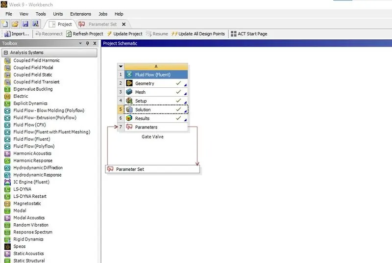
STEPS USED FOR SIMULATIONS
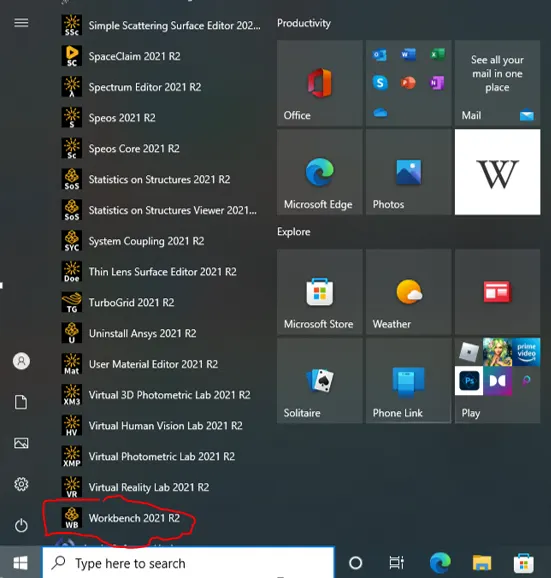
Click on red encircled "Workbench 2021 R2" as shown in the above image to start the simulation.
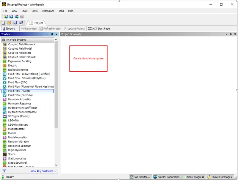
Click On Fluid Flow (Fluent) under Analysis Systems and drag it to create a standalone system. Rename the project as Gate Valve.
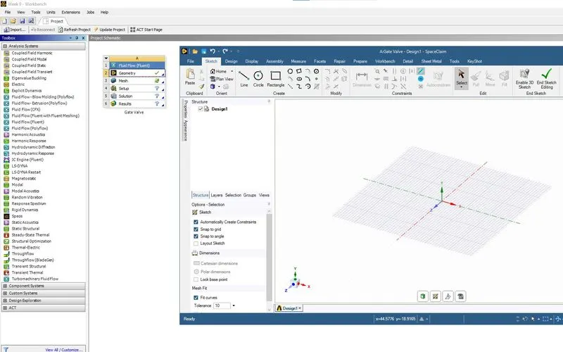
Click on the Geometry to open the space claim window.
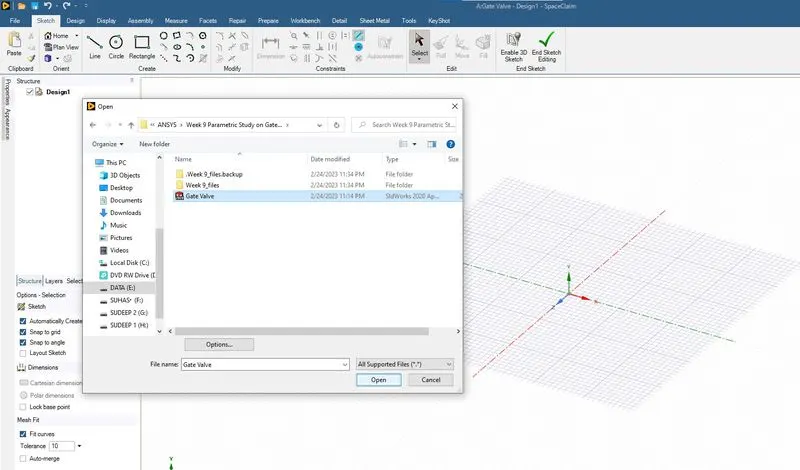
Open the Gate Valve.STEP file as shown in the above image.
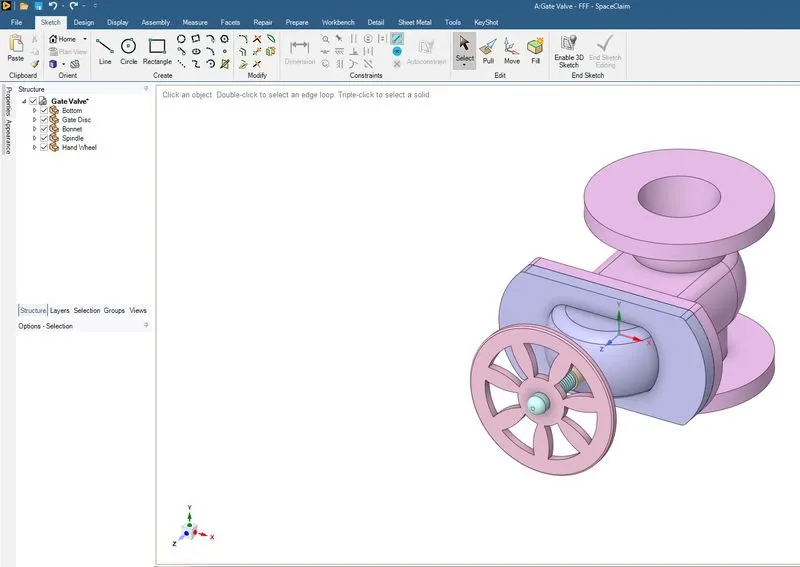
The preview of the Gate valve in the space claim window as shown in the above image.
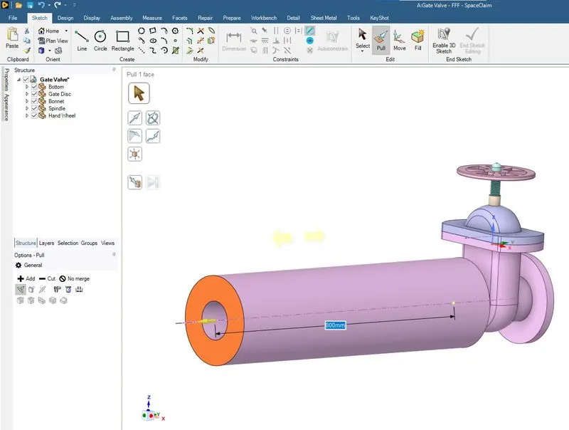
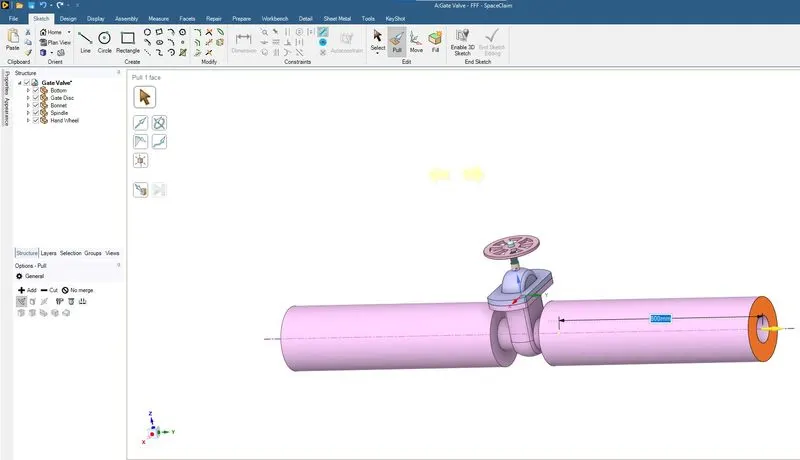
The both ends of the gate valve is extended by 800mm using Pull command as shown in the above image.
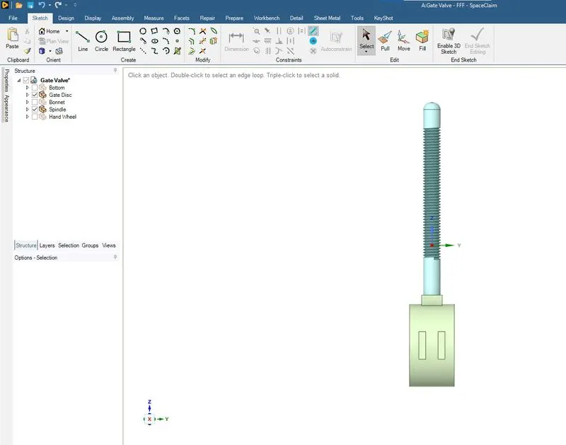
Except gate disc and spindle everything is hidden by unticking as shown in the above image.
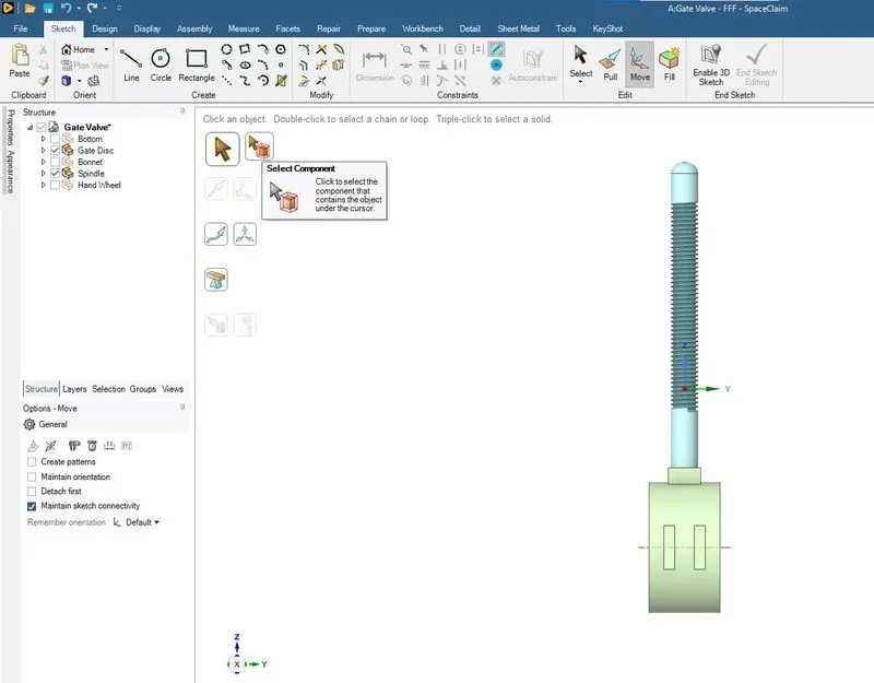
The move command is used to move the component in Z direction as shown in the above image. Using select component and then doing a box selection by dragging the component is selected.
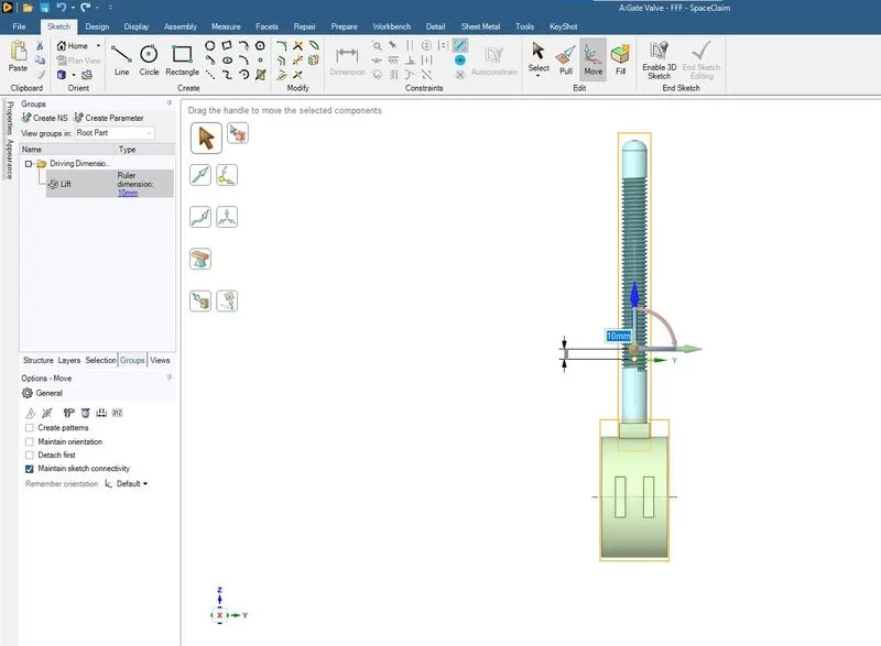
The moving distance is enetered in the ruler dimension as shown in the above image. Using the Create Parameter under Groups the entered dimension is parametrized and it is named as Lift.
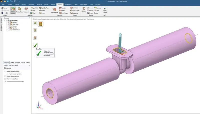
Now the fluid volume is extracted by selecting the yellow highlighted edges as shown in the above image.
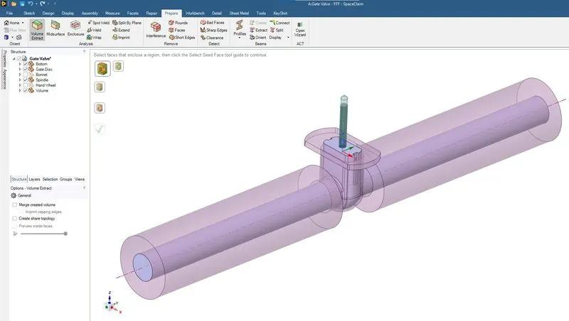
The preview of the fluid volume extracted as shown in the above image.
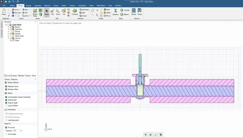
The cut section of the fluid voulme and geometry as shown in the above image.
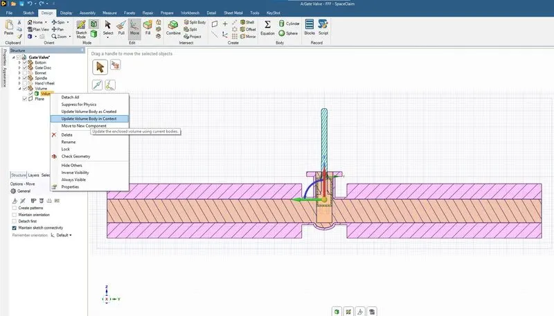
Using the update volume body in context as shown in the above image so that fluid volume is updated when the parameter is changed or updated.
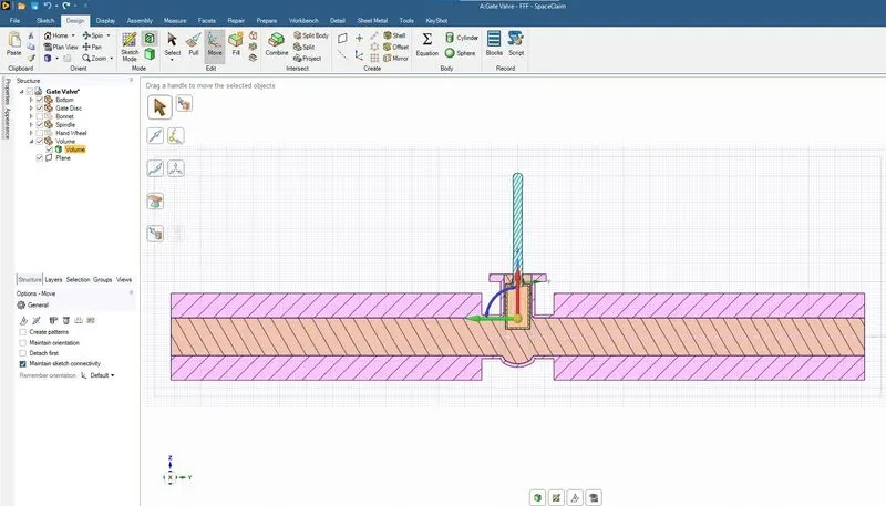
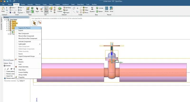
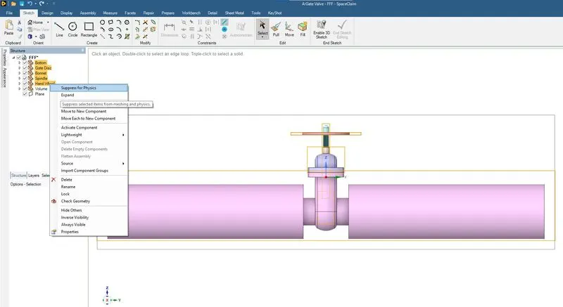
Except fluid volume which is the area of interest the rest evething is suppress for physics.
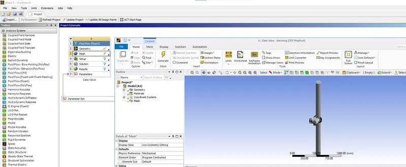
Using the Mesh the meshing window is opened
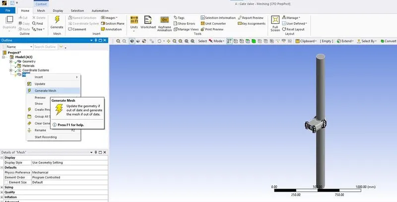
A default mesh is generated using the Generate Mesh as shown in the above image.
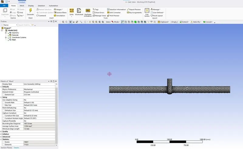
Refining of mesh by element sizing of 25mm.
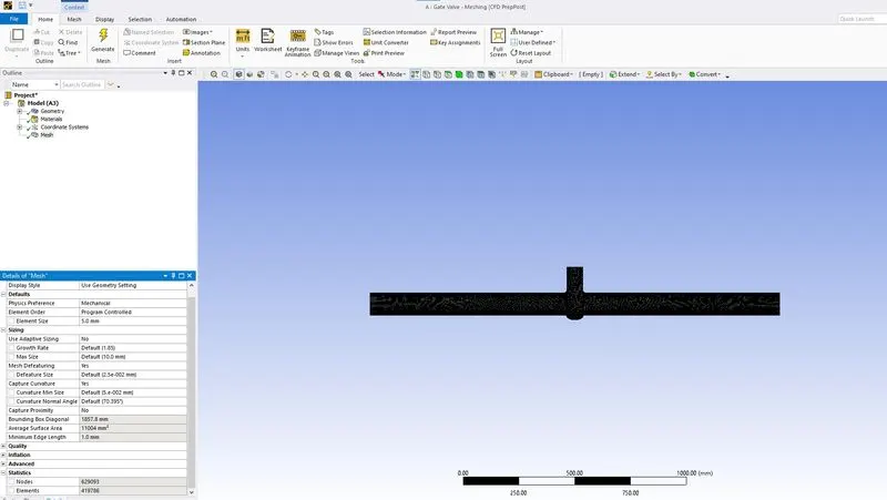
Refining of mesh by element sizing of 5mm.
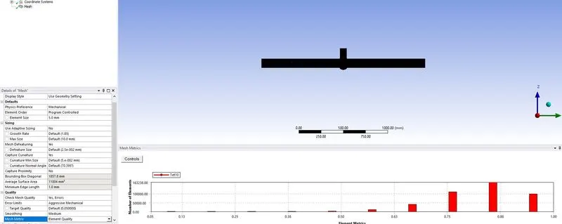
Element quality as shown in the above image.
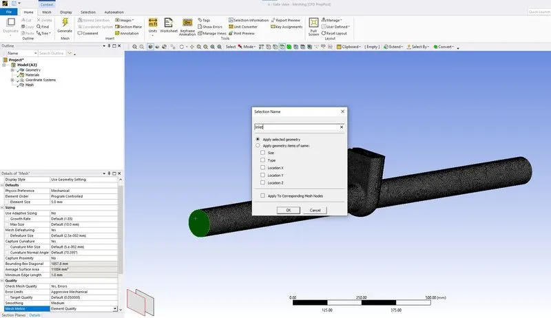
Using the named selection the selected face is named as Input.
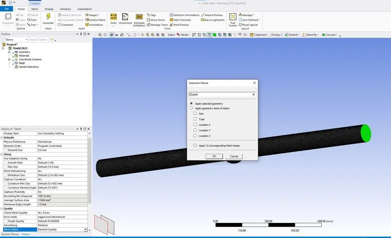
Using the named selection the selected face is named as Output.
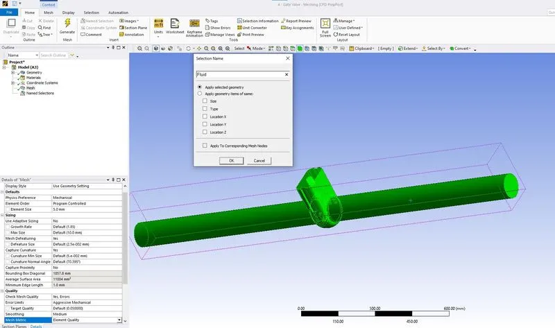
Using the named selection the selected body is named as Fluid.
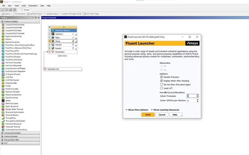
Ansys fluent setup is started as shown in the above image.
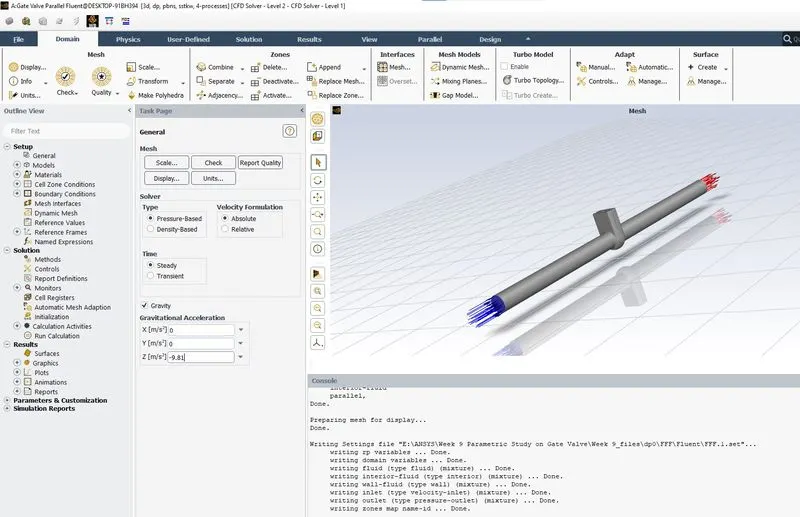
Gravity is enabled as shown in the above image.
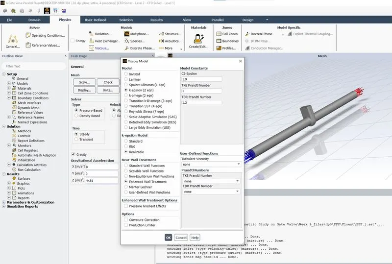
Viscous model is set as k-epsilon Realizable Enhanced wall treatment as shown in the above image.
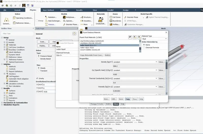
Using Create materials , water liquid material is added from fluent database as shown in the above image.
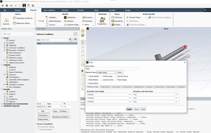
Using cell zone condition, the fluid is set water-liquid as shown in the above image.
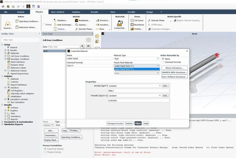
water-liquid is set as material as shown in the above image.
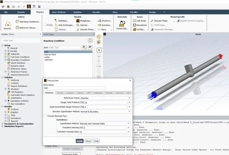
Inlet pressure boundary condition as shown in the above image.
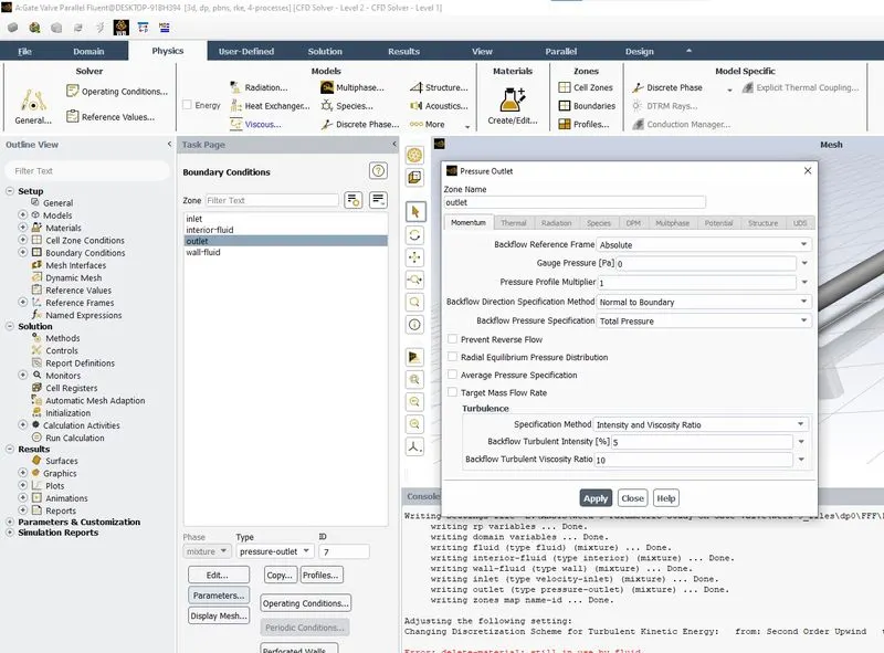
Outlet boundary condition as shown in the above image.
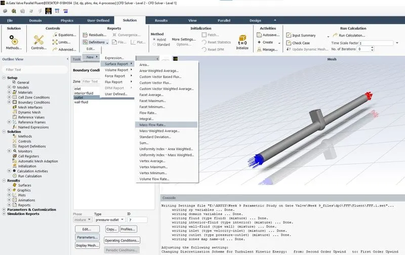
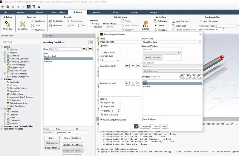
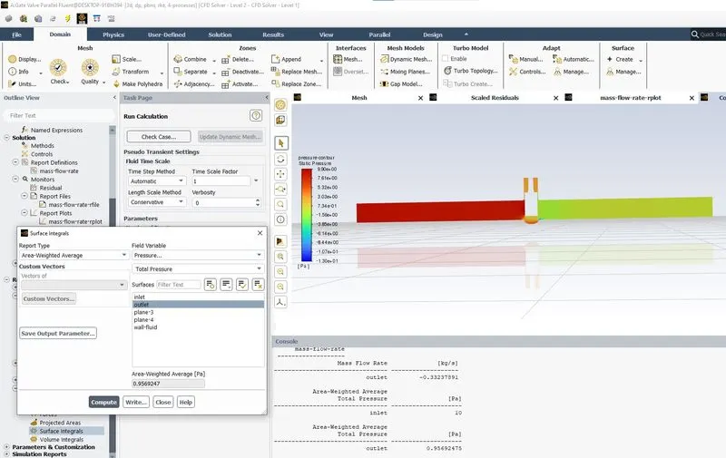
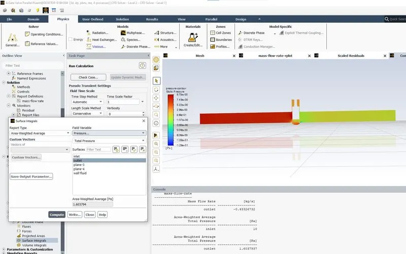
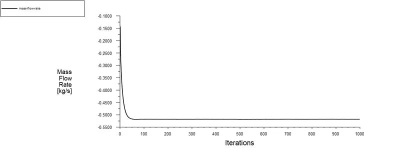
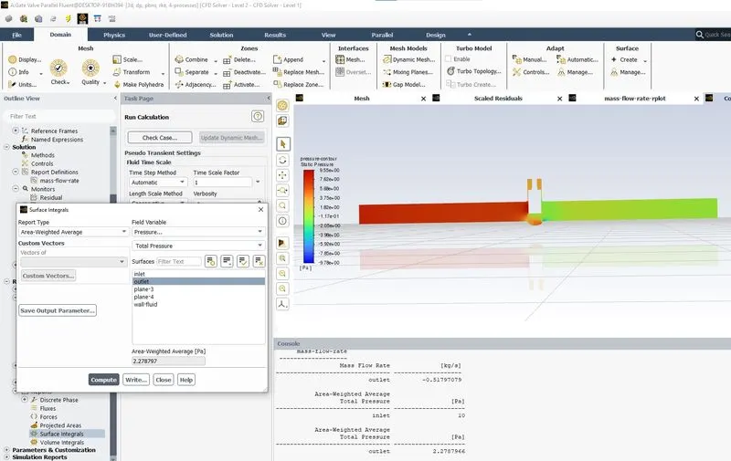
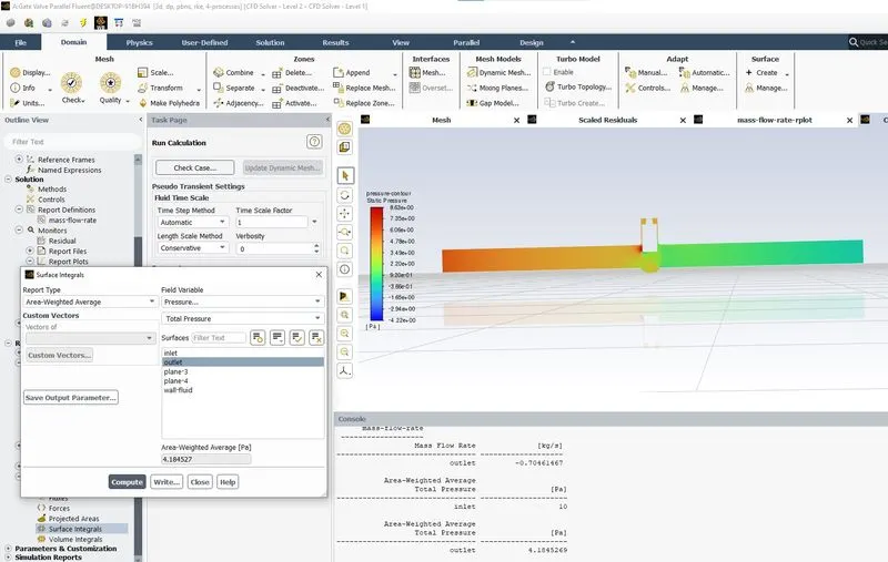
Surface report for mass flow rate is defined as shown in the above two image.
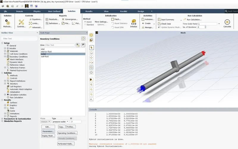
Hybrid initialization is done as shown in the above image.
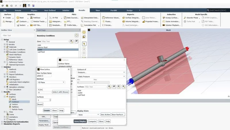
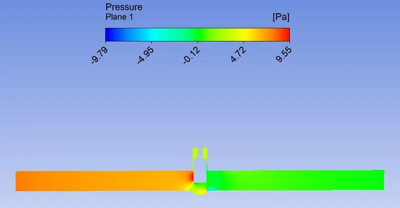
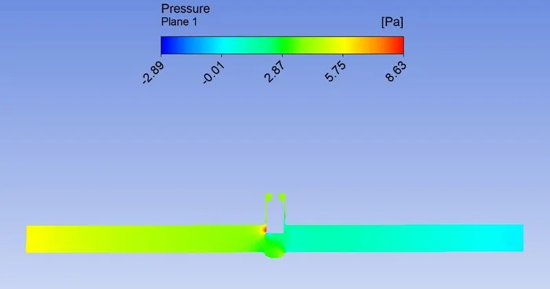
Pressure contour is defined as shown in the above image.
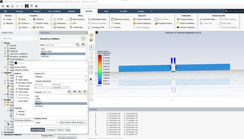
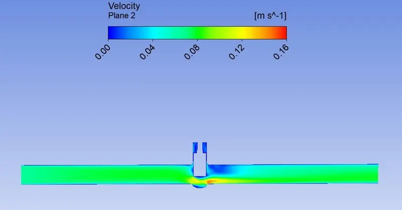
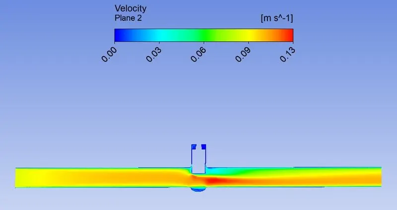
Velocity contour is defined as shown in the above image.
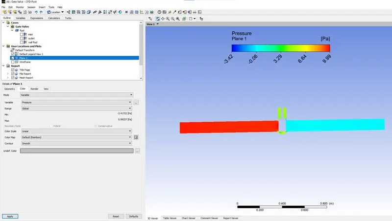
Pressure contour plotted using the CFD post.
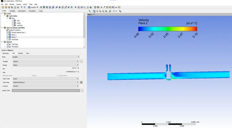
Velocity contour plotted using the CFD post.
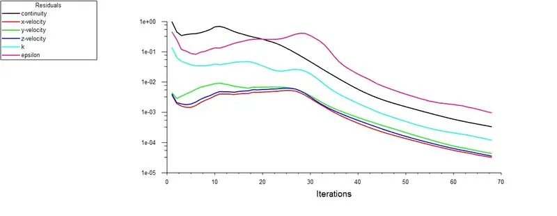
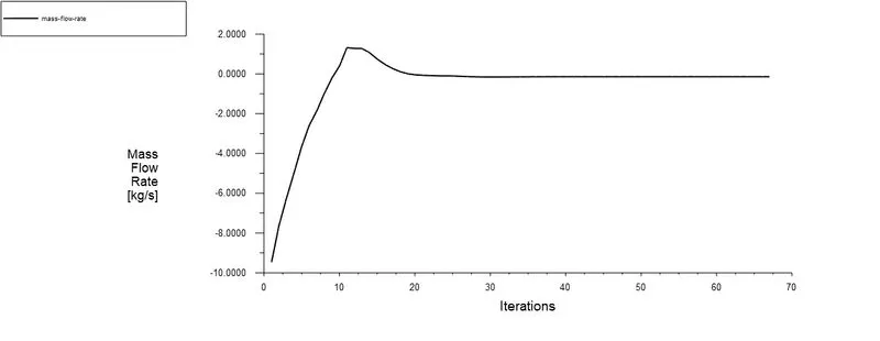
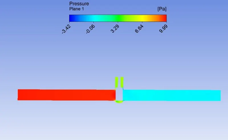
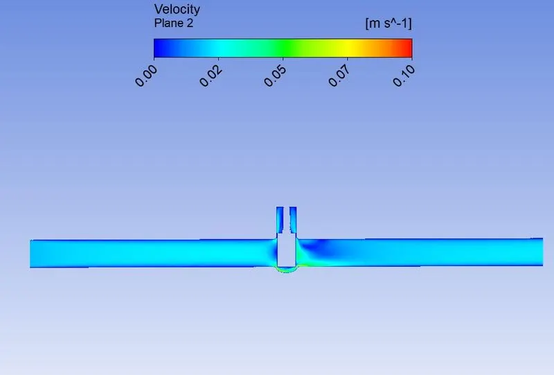
Case 1: 10mm Lift
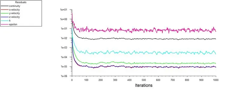
1.1 Scaled Residuals
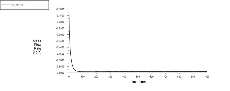
1.2 Area weighted average surface plot for mass flow rate
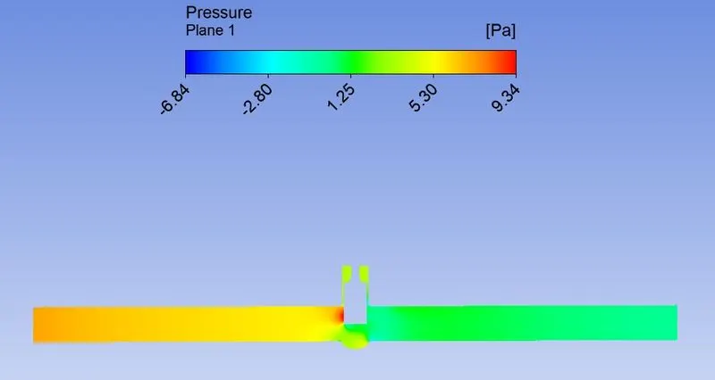
1.3 Pressure Contour
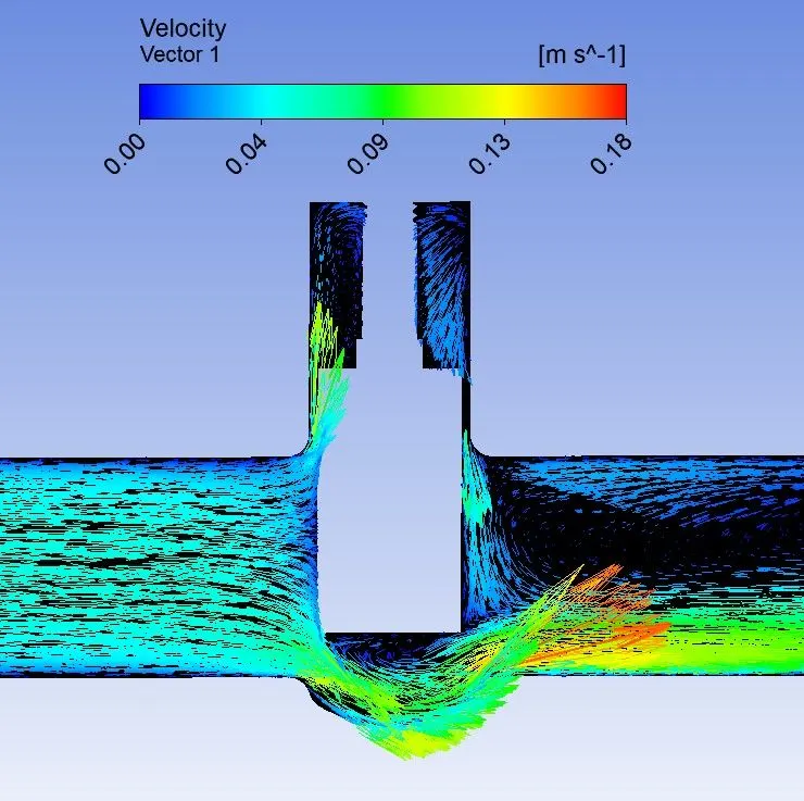
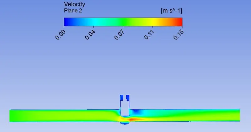
1.4 Velocity Contour
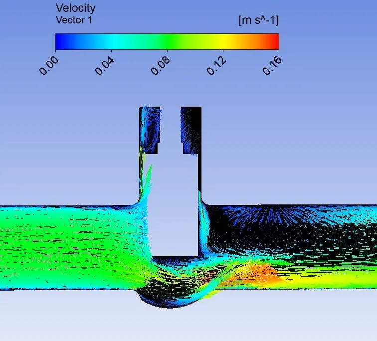
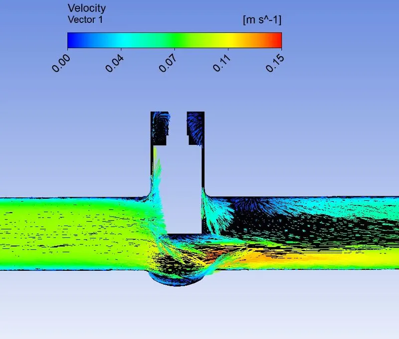
1.5 Velocity Vector
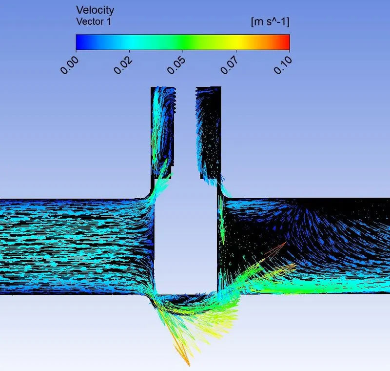
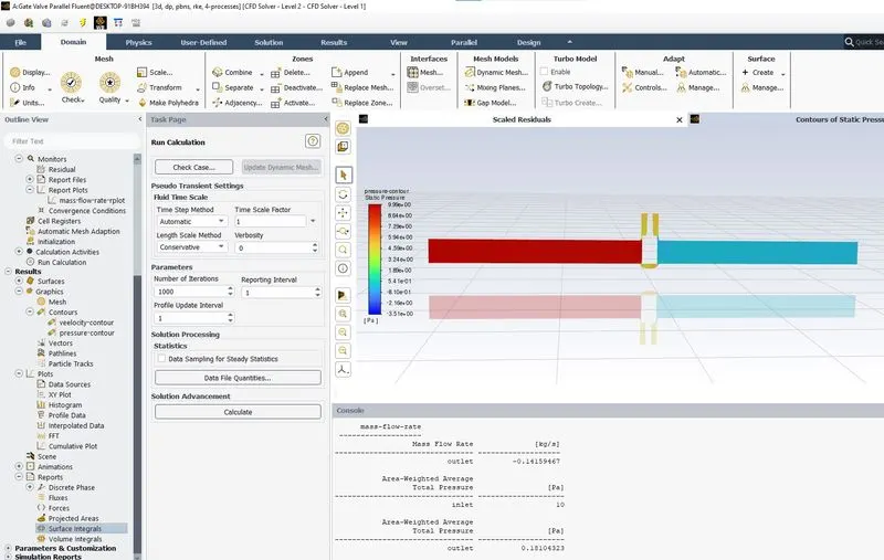
Case 2: 20mm Lift
2.1 Scaled Residuals
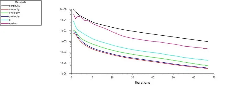
2.2 Area weighted average surface plot for mass flow rate
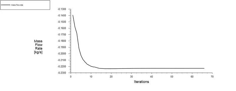
2.3 Pressure Contour
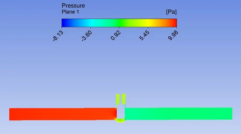
2.4 Velocity Contour
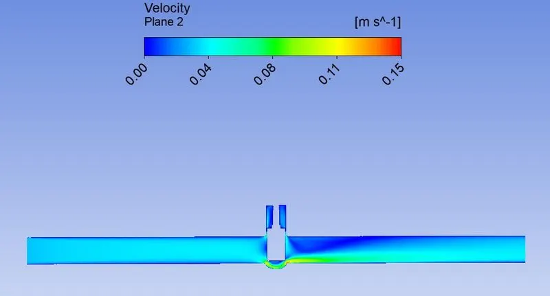
2.5 Velocity Vector
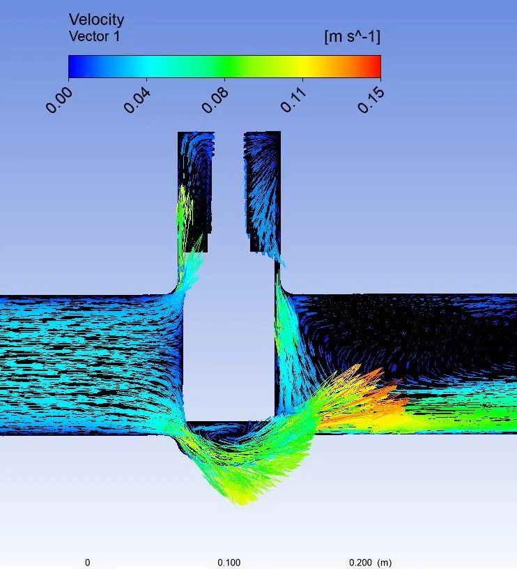
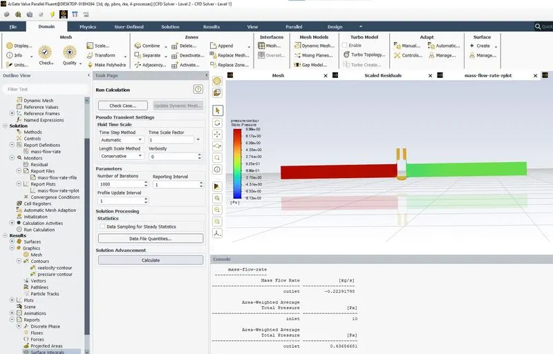
Case 3: 30mm Lift
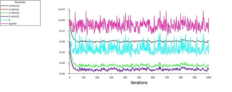
3.1 Scaled Residuals
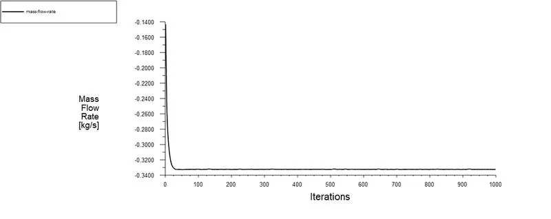
3.2 Area weighted average surface plot for mass flow rate
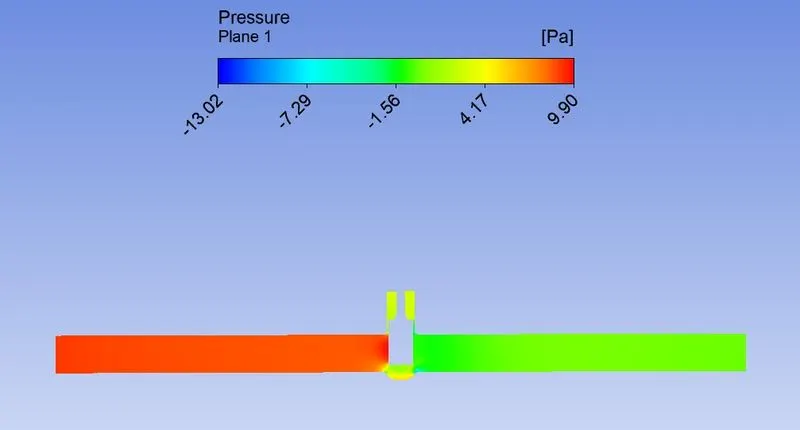
3.3 Pressure Contour
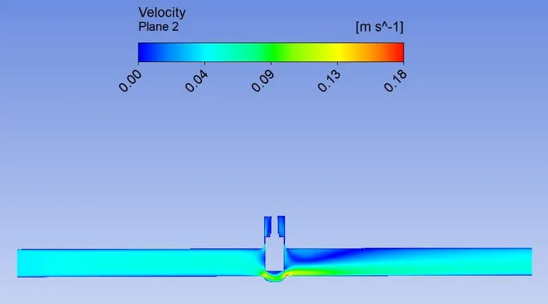
3.4 Velocity Contour
3.5 Velocity Vector
Case 4: 40mm Lift
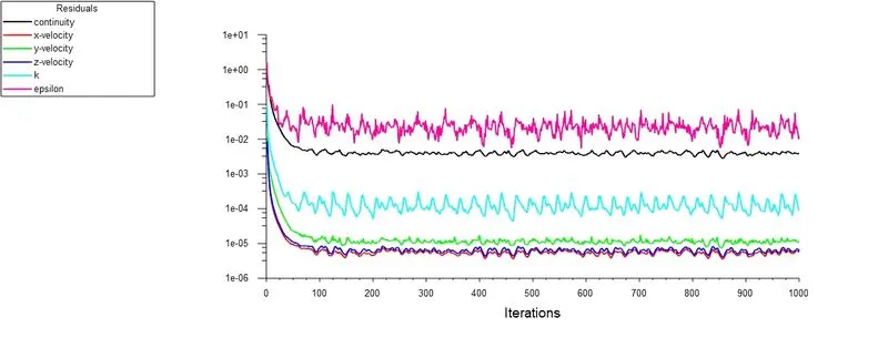
4.1 Scaled Residuals
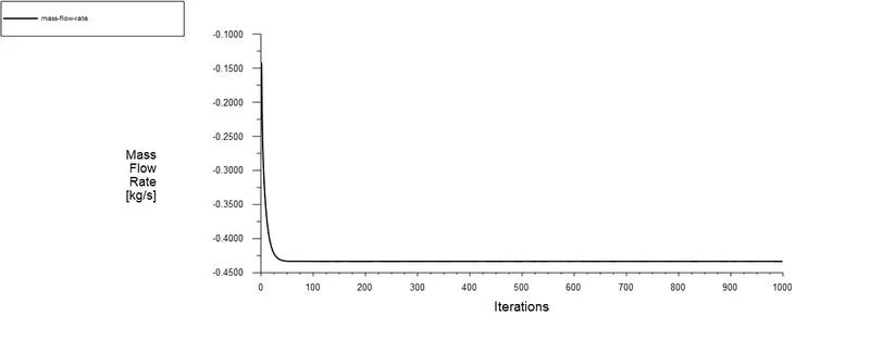
4.2 Area weighted average surface plot for mass flow rate
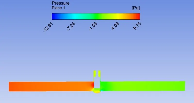
4.3 Pressure Contour
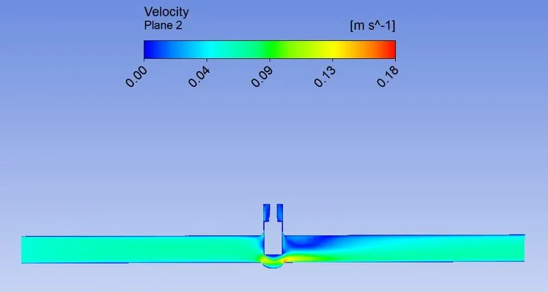
4.4 Velocity Contour
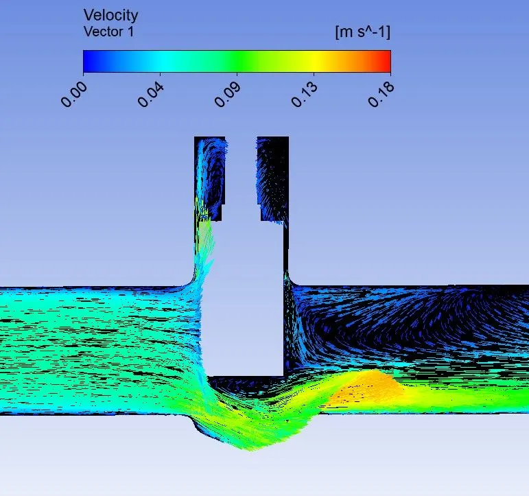
4.5 Velocity Vector
Case 5: 50mm Lift
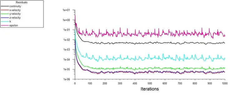
5.1 Scaled Residuals
5.2 Area weighted average surface plot for mass flow rate
5.3 Pressure Contour
5.4 Velocity Contour
5.5 Velocity Vector
Case 6: 60mm Lift
6.1 Scaled Residuals
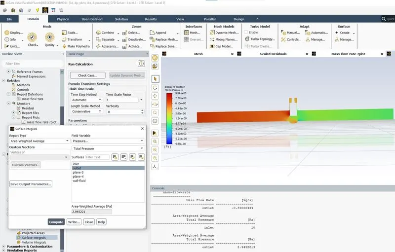
6.2 Area weighted average surface plot for mass flow rate
6.3 Pressure Contour
6.4 Velocity Contour
6.5 Velocity Vector
Case 7: 70mm Lift
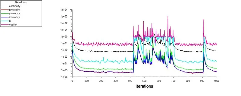
7.1 Scaled Residuals
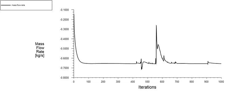
7.2 Area weighted average surface plot for mass flow rate
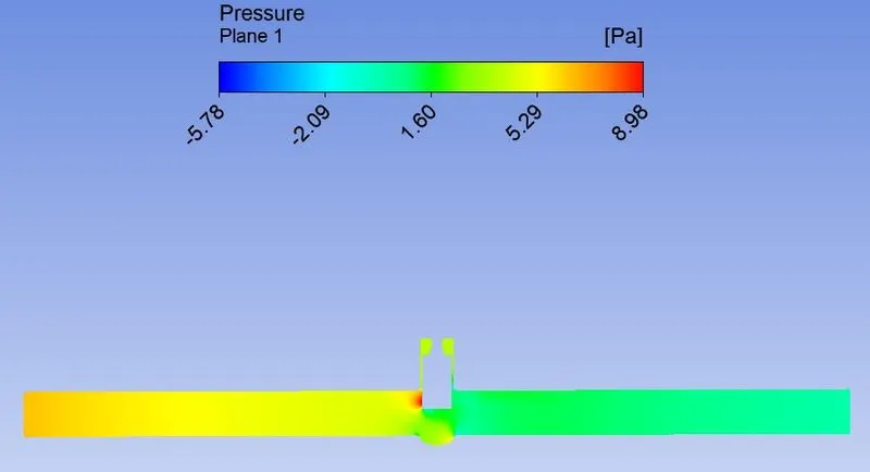
7.3 Pressure Contour
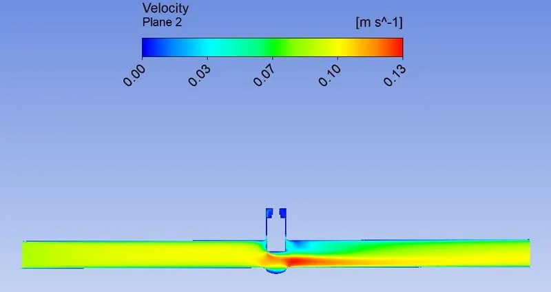
7.4 Velocity Contour
7.5 Velocity Vector
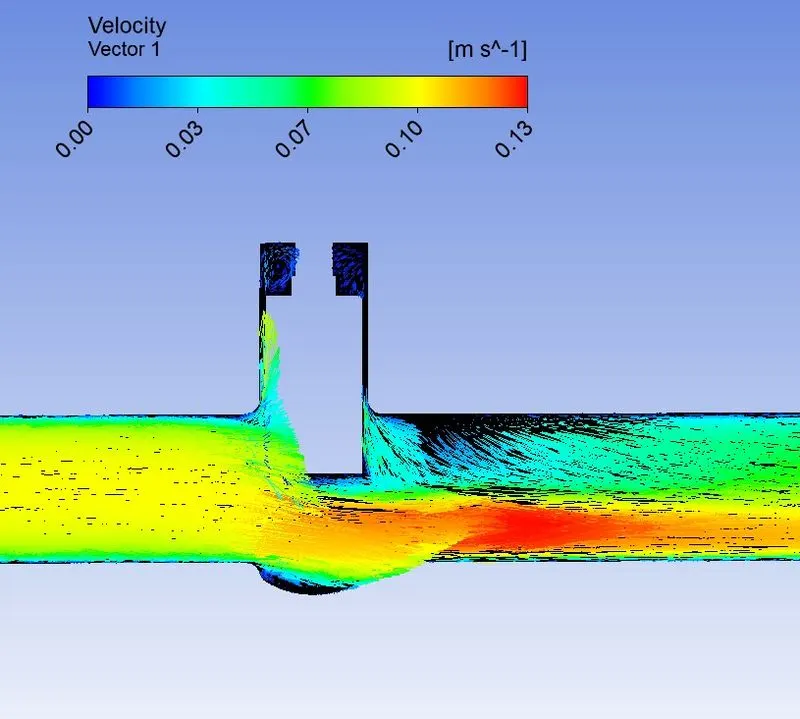
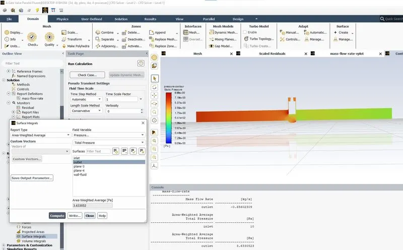
Case 8: 80mm Lift
8.1 Scaled Residuals
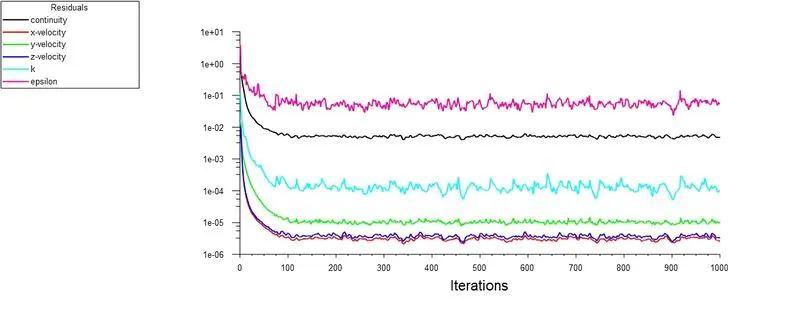
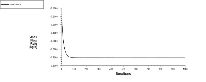
8.2 Area weighted average surface plot for mass flow rate
8.3 Pressure Contour
8.4 Velocity Contour
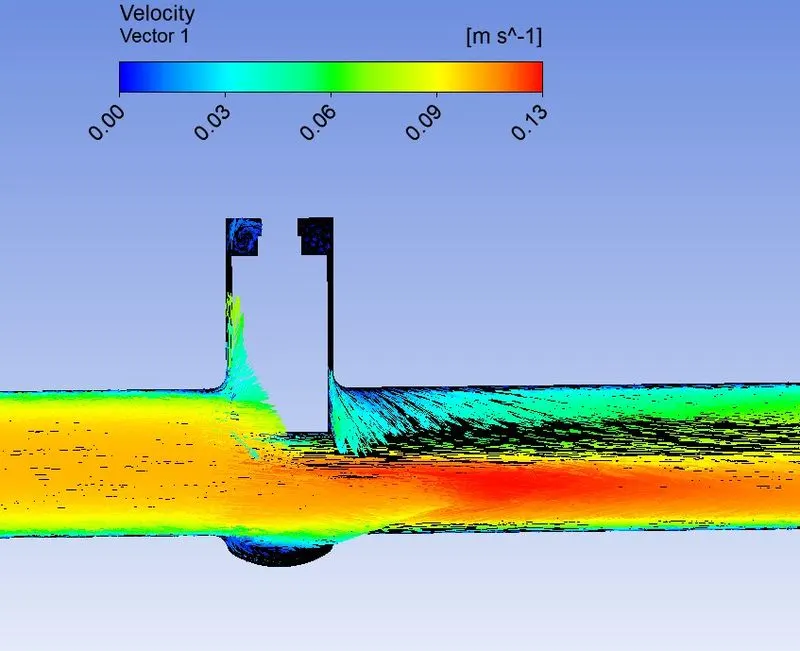
8.5 Velocity Vector
SUMMARY
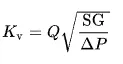
The metric equivalent flow factor (Kv) is calculated using metric units :
where,
Kv is the flow factor (expressed in m3·h−1).
Q is the flowrate (expressed in cubic metres per hour m3·h−1),
SG is the specific gravity of the fluid (for water = 1),
∆P is the differential pressure across the device (expressed in bar).

CONCLUSION
- A parametric study on the gate valve simulation by setting the opening at different lift has been performed using Ansys Fluent.
- Mass flow rate has been obtained at the outlet for each design point.
- Mass flow rate increases with the opening of the valve. Mass is maximum when the valve is fully opened.
- Pressure at the inlet is maximum when the valve is closed.
- Velocity tends to increase with the opening of the valve and stabilizes after certain opening percentage of the valve.
- Flow factor(Kv) increases with an increase in the valve opening.
- Flow coefficient (Cv) increases with an increase in the valve opening.