Week 2 Challenge : Surface meshing on a Pressure valve
Aim/Objective :
a) Check for geometrical errors and perform Topology cleanup accordingly
b) Surface meshing on a Pressure valve for three different target lengths as three different cases.
Given:
- Challenge2_valve.ansa file
- Element type = Tria
- Case1 : Target length = 5mm
- Case2 : Target length = 3mm
- Case3 : Target length = 1mm
PRESSURE VALVE (RELIEF VALVE)
A relief valve or pressure relief valve (PRV) is a type of safety valve used to control or limit the pressure in a system; pressure might otherwise build up and create a process upset, instrument or equipment failure, or fire. The pressure is relieved by allowing the pressurized fluid to flow from an auxiliary passage out of the system.
The relief valve is designed or set to open at a predetermined set pressure to protect pressure vessels and other equipment from being subjected to pressures that exceed their design limits. When the set pressure is exceeded, the relief valve becomes the "path of least resistance" as the valve is forced open and a portion of the fluid is diverted through the auxiliary route.
BASIC STEPS TO BE FOLLOWED WHILE STARTING THE ANSA
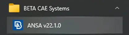
Click on the ANSA v22.1.0 in the Start Menu to open the ANSA software.
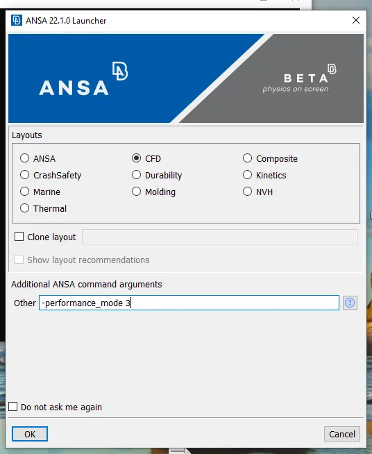
After clicking the ANSA v22.1.0 the above window pops up. In the above poped up window, select the CFD in Layouts.
In additional ANSA command arguments change the other to -performance_mode 3
Always remember not to click/tick on Dont ask me again. Finally click the OK button.
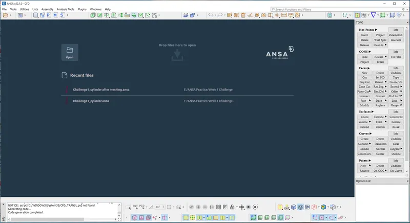
After opening the above window, right click on the top tab with icons and select the show labels and click apply to all
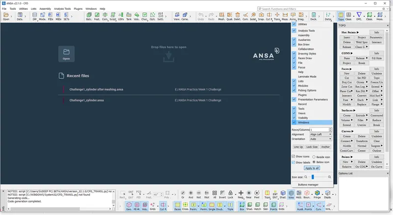
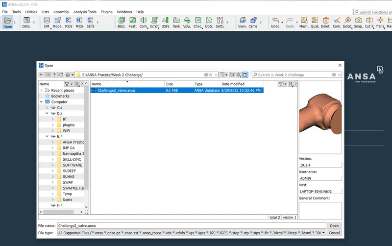
Open the downloaded Challenge2_valve.ansa file as shown below
The above file will be opened in wireframe mode.
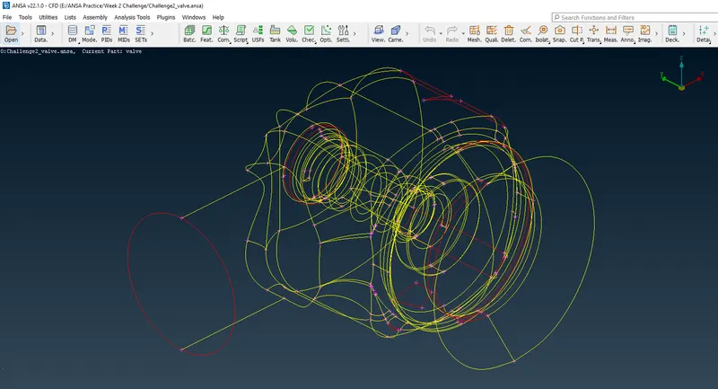
On opening the model you will see the following:
Single cons, Red cons or Double cons and hot points.
Our first target would be to remove the Red cons
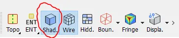
Turn on the shading mode
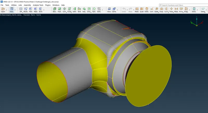
by clicking the following button encircled in red colour.
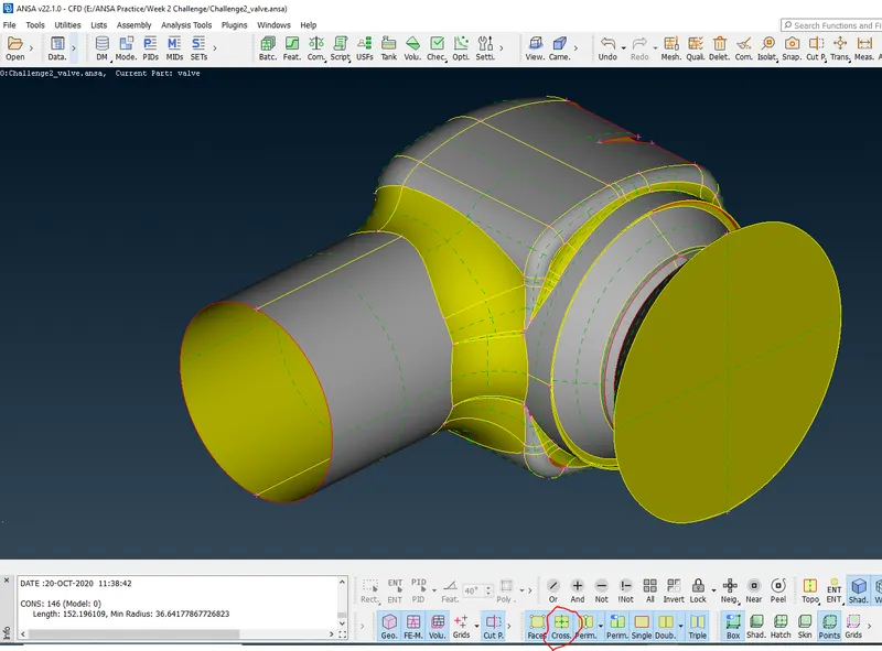
To display the cross hatches of the faces click on the red encircled button in the below figure.
Next step to be followed is to perform topology based on Tolerance values of Settings
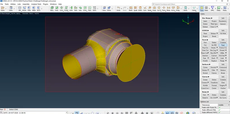
Select Topo under Faces and then left click and drag to make the selection box.
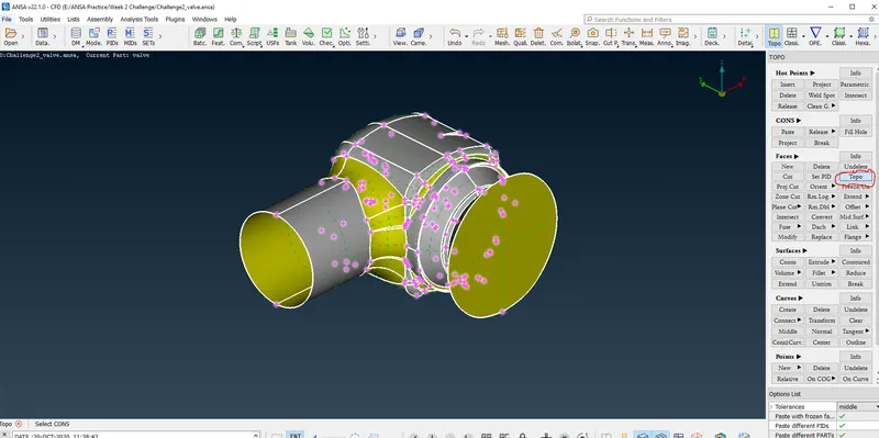
After the selection box is made the above figure represents how it will be visible.
Press the middle button or scroll of the mouse to perfom the basic topo clean up
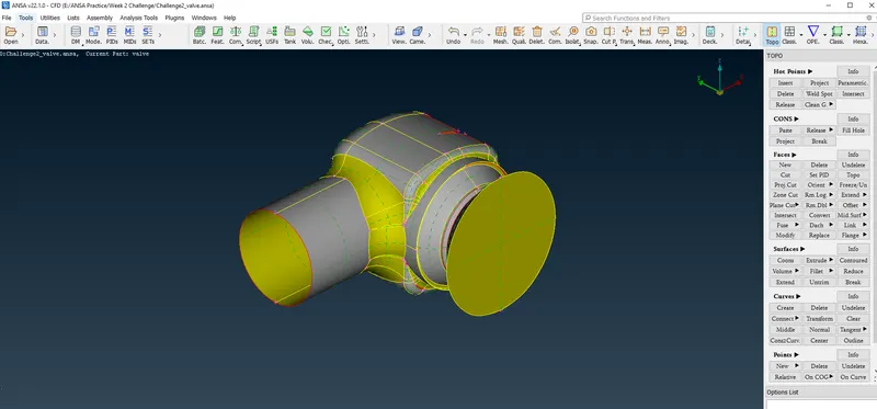
What does a TOPO aid us in?
If there is an error that can be automatically fixed TOPO will do that for us and help in reducing the errors.
Whichever errors are not fixed by the TOPO has to rectified manually.
Using Ctrl + Shift we can do the switching of the views from shading to wireframe and vice versa. This option helps to view to selected CONS is proper or not.
(Ctrl + Shift) [On Key Board] + (Right / Left Click) [On Mouse] you can rotate
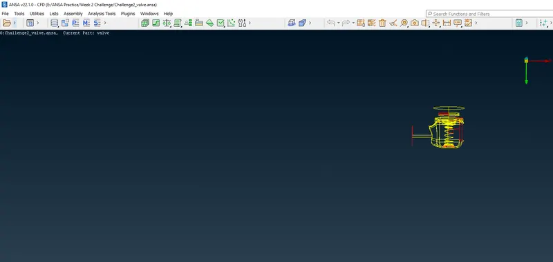
On clickcing the F9 button the above gets fitted to the screen.
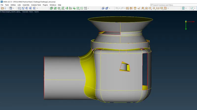
Now we start removing the red cons. The quadrlateral red cons visible on the body surface will be rectified using Fill Hole under CONS in TOPO
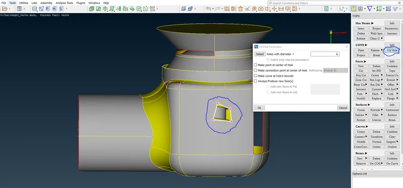
Please see the blue encirled for Fill Hole option and slection of quadrilateral hole.
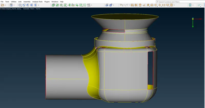
Press the middle mouse button or scroll and then click OK. The quadrilaeral hole vanishes.
Our next red cons is as shown below highlighted in red encircled, which we will rectify using the Fill Hole option.
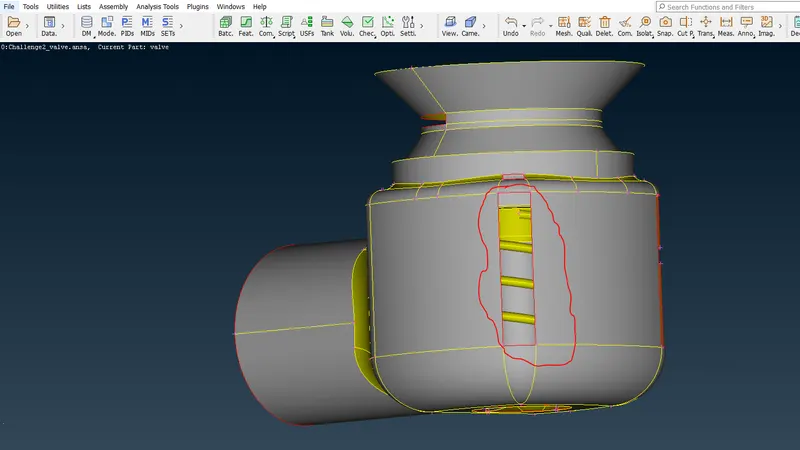
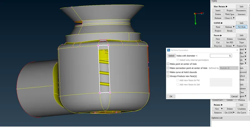
Select Fill Hole, click on the surface edge where it has to be applied. Refer above image to see the selection.
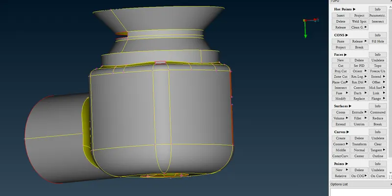
Press the middle mouse button or scroll and then click OK. The second red cons vanishes as we see in the above image.
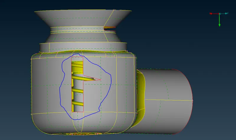
Now we will attempt to rectify the red cons encircled in blue as shown in the above figure using Fill Hole option.
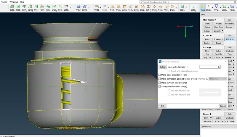
Select Fill Hole, click on the surface edge where it has to be applied. Refer above image to see the selection.
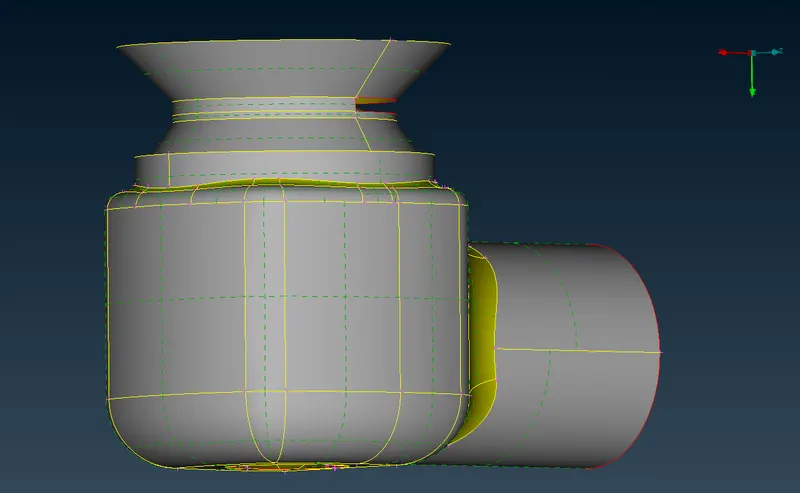
Press the middle mouse button or scroll and then click OK. The third red cons vanishes as we see in the above image.

We attempt to rectify the red cons encircled in blue in the above figure.
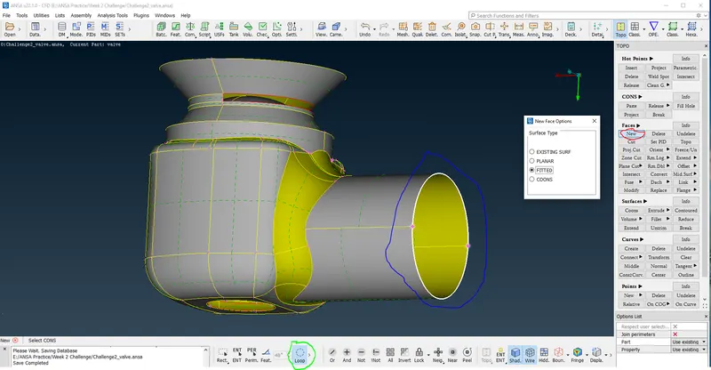
In TOPO under Faces select New (encircled in red), a window pops up for New Face Options, in that we select Surface Type as FITTED then usin the loop (encircled in green) we click on the surface edge (encircled in blue).
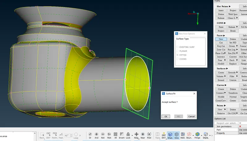
After clicking the middle mouse button / scroll, reference selection is highlighted (Refer above figure). A new window Surface Fit pops up.
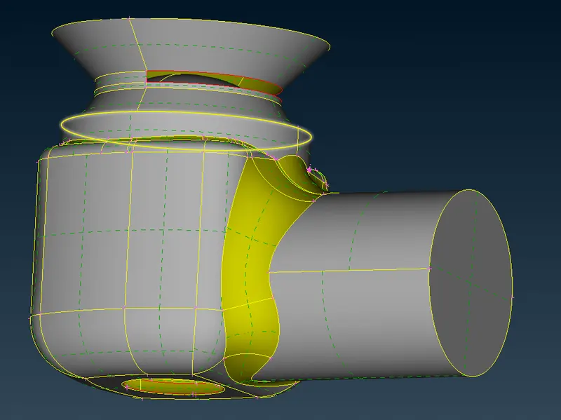
After clicking OK on the window Surface Fit. The open surface gets filled and the red cons is rectified as shown in the above window.
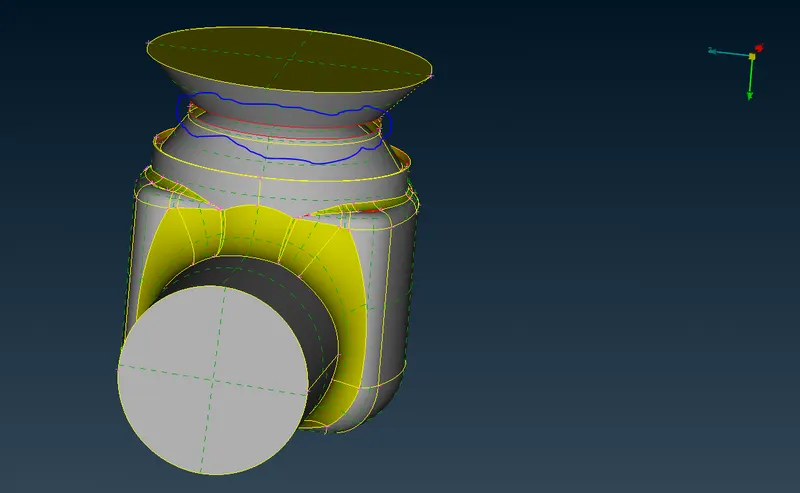
Now we will go for rectifying another red cons encircled in blue (refer above figure)
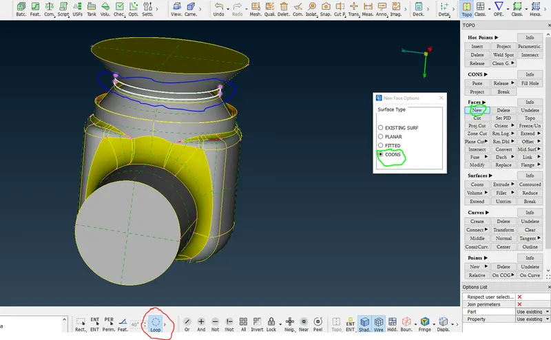
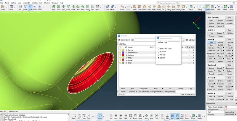
In TOPO under Faces click New (encircled in green), a new window New Face Options pops up. In New Face Options window under Surface Type select COONS (encircled in green).
Using Loop (encircled in red), make a selection of the curved surface encircled in blue.
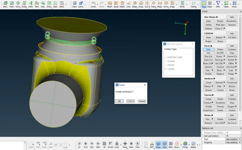
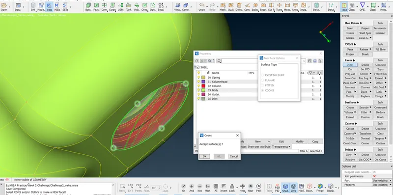
After selection of the curved surface press the middle mouse button or scroll, a temporary surface is shown for us to indicate how the surface will be generated at the surface selected. Also a new window Coons pop up where we click OK.
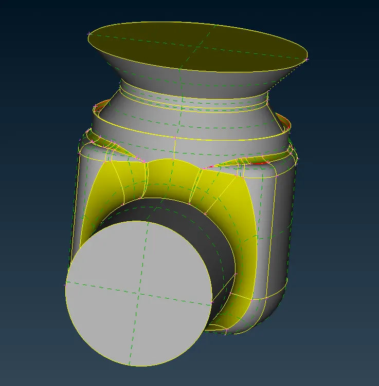
After accepting the surface the curved surface will be generated and our red cons at the curved surface will get resolve.
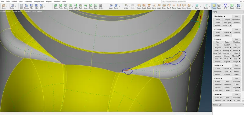
Now we will attempt the rectification of two red cons encircled in blue (Refer above figure).
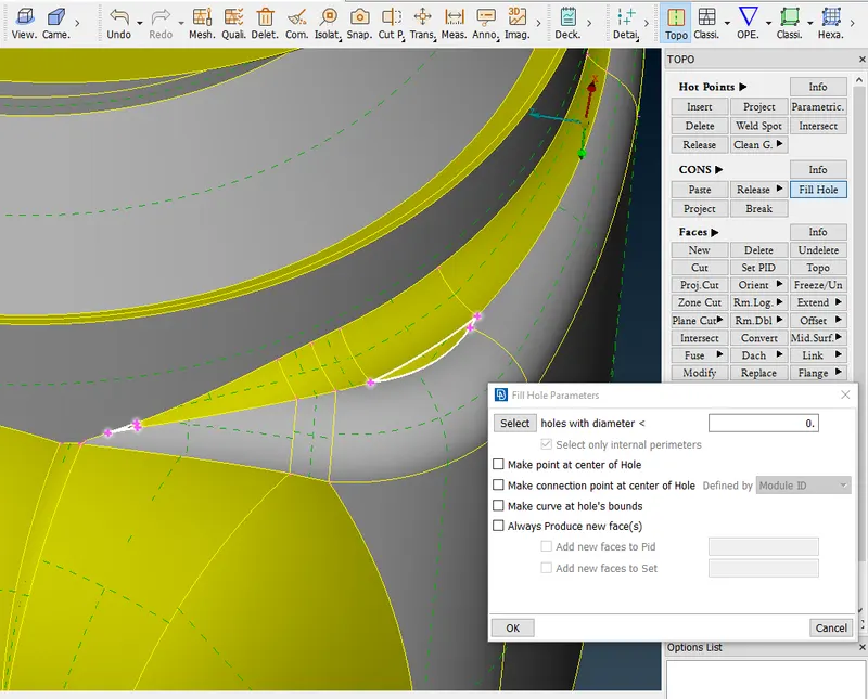
Using fill hole we make the surfaces at the red cons. Here we can see that we can do multiple selction Fill Hole.
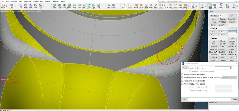
In the above image there is one unchecked face has been generated at the red circled region where fill hole has been done.
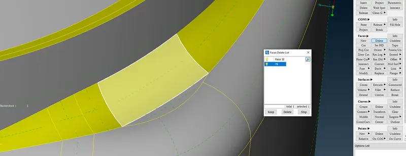
Using Delete under the Faces we delete surface and create a new better surface
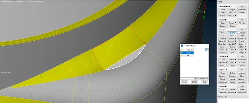
We delete the faces by selecting the proper Face Id
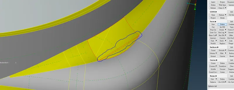
Now the unchecked face is now visible encircled in blue. Refer above figure.
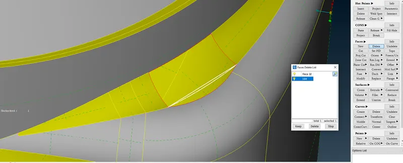
We delete the uncheked surface using Delete option under Faces in TOPO
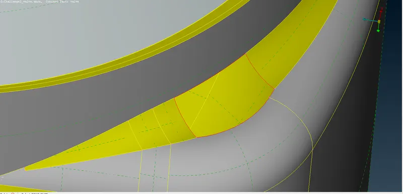
Now we see that unchecked face is removed and now we one red cons is present where we wil create a new face using COONS option.
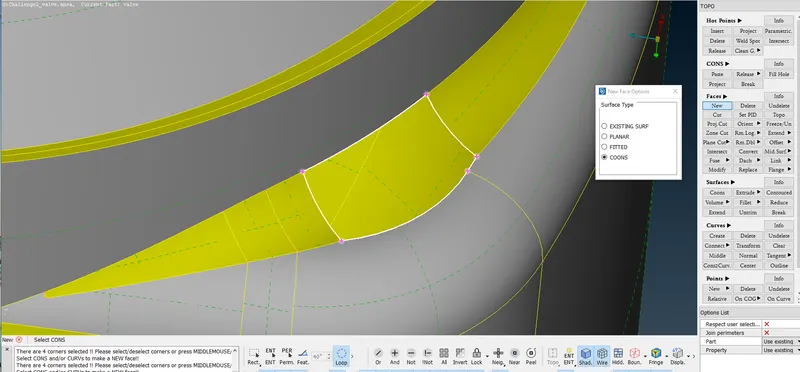
Select New under Faces in TOPO, a New Face Options window pops up where we select COONS and then by using Loop we select surface edge where a new surface has to be created.
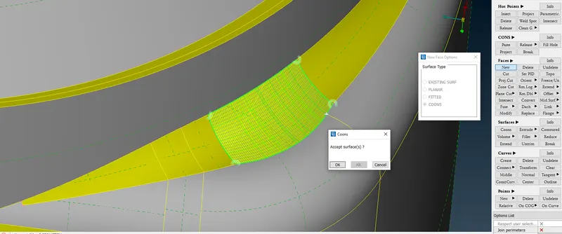
After clicking the middle mouse button / scroll a temporary surface is highlighted to know how the surface will be generated at the selected red cons. If we find the surface generated is fine for us we click OK in the Coons window.
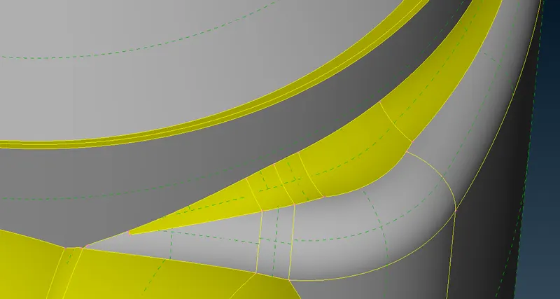
After clicking OK the new surface is generated and the red cons is resolved.
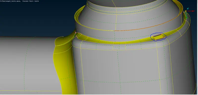
Now we will go for rectifying the blue encircled red cons. We can either do by Fill Hole or By creating New Faces using COONS.
We are trying to do using COONS red cons is present on the curved surface.
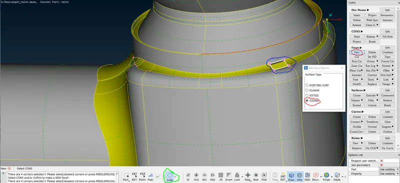
Select New under Faces in TOPO, a New Face Options window pops up where we select COONS and then by using Loop we select surface edge where a new surface has to be created.
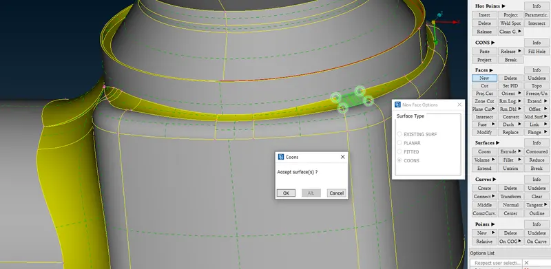
After clicking the middle mouse button / scroll a temporary surface is highlighted to know how the surface will be generated at the selected red cons. If we find the surface generated is fine for us we click OK in the Coons window.
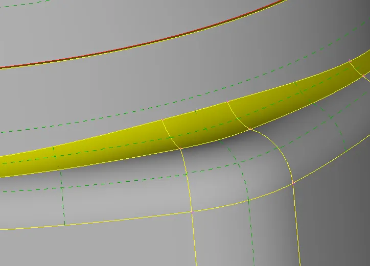
After clicking OK the new surface is generated and the red cons is resolved.
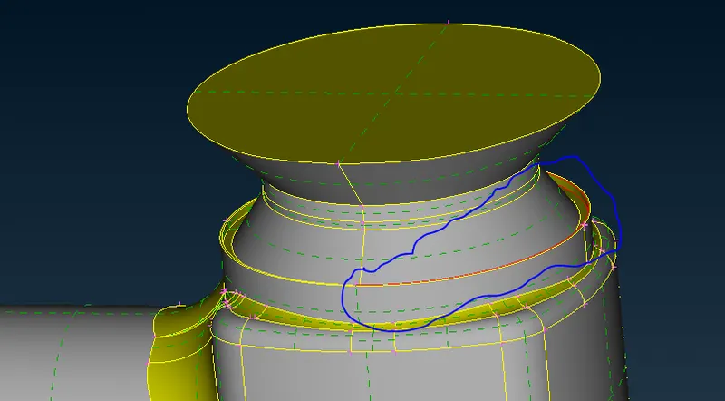
Now we are attempting to resolve the above blue encircled red cons which is not properly visible in the shading mode.
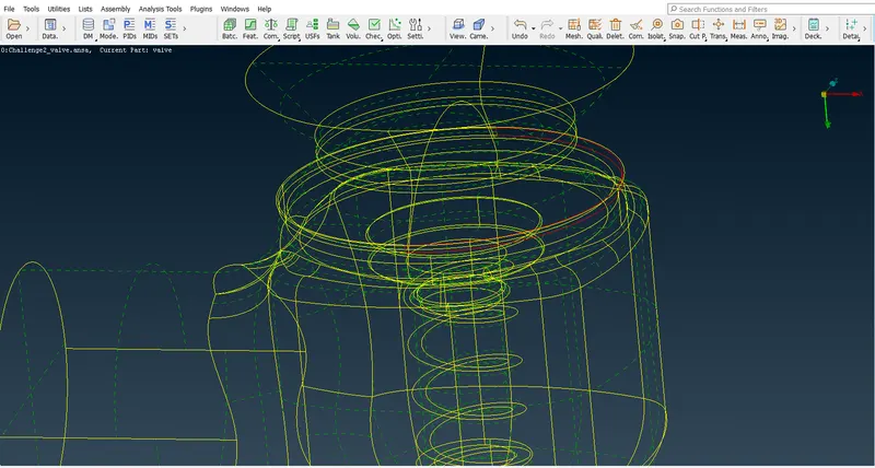
Hence we do the ctrl + shift to change to wireframe mode where we can clearly see the red cons present.
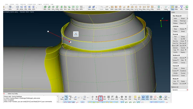
To visualize the red cons in the shading mode we use the option Not encirled in Red and select the arrow highlighted portion and selected surface get hidden.
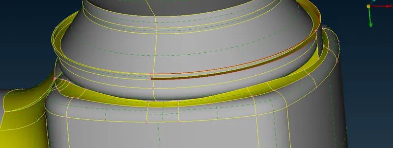
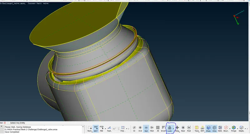
Always do the Lock so that hidden surfaces remain hidden until the lock is applied even if the All is clicked
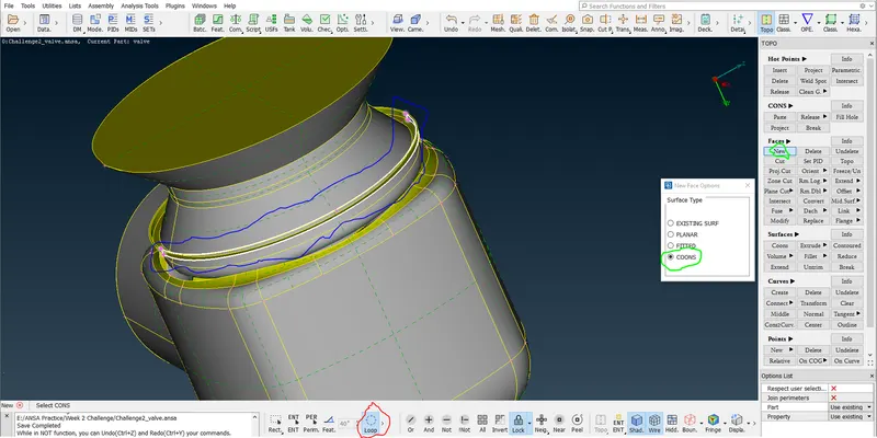
Select New under Faces in TOPO, a New Face Options window pops up where we select COONS and then by using Loop we select surface edge where a new surface has to be created.
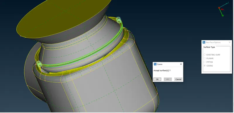
After clicking the middle mouse button / scroll a temporary surface is highlighted to know how the surface will be generated at the selected red cons. If we find the surface generated is fine for us we click OK in the Coons window.
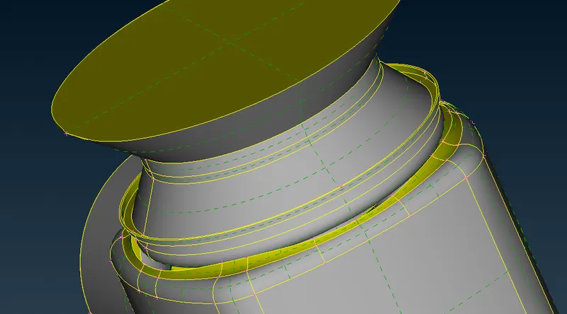
After clicking OK the new surface is generated and the red cons is resolved.
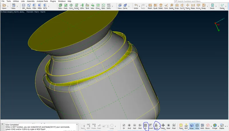
Once the surface is generated and red cons is resolved, remove the Lock and Select All.
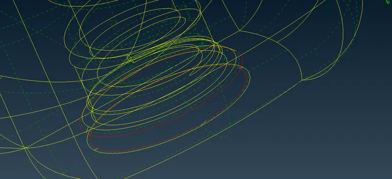
Now there are red cons present at the bottom or base of the stem.
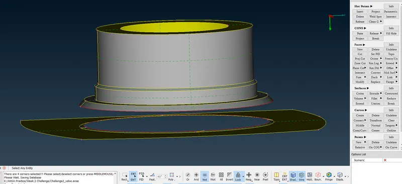
We highlight the portion of interest by using the Not option and do the lock so that we can work at the interested portion of the geometry without any worry to repeat the highlight the area of interest. Now we clearly see the red cons which will attempt to resolve.
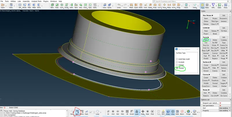
Select New under Faces in TOPO, a New Face Options window pops up where we select COONS and then by using ENT entity mode we select edges where a new surface has to be created.
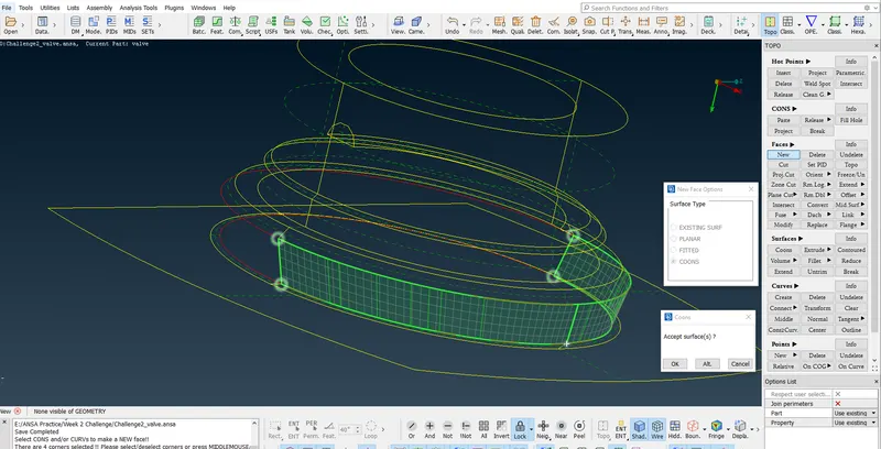
After clicking the middle mouse button / scroll a temporary surface is highlighted to know how the surface will be generated at the selected red cons. If we find the surface generated is fine for us we click OK in the Coons window.
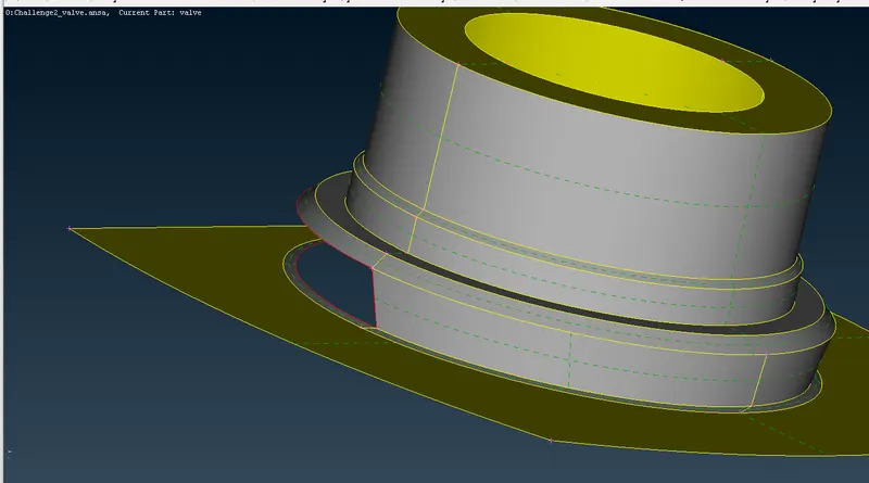
After clicking OK the new surface is generated and the red cons is resolved partially.
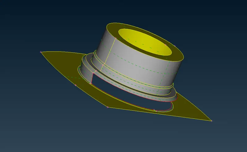
Our area of interest to resolve the red cons has been shown in above figure.
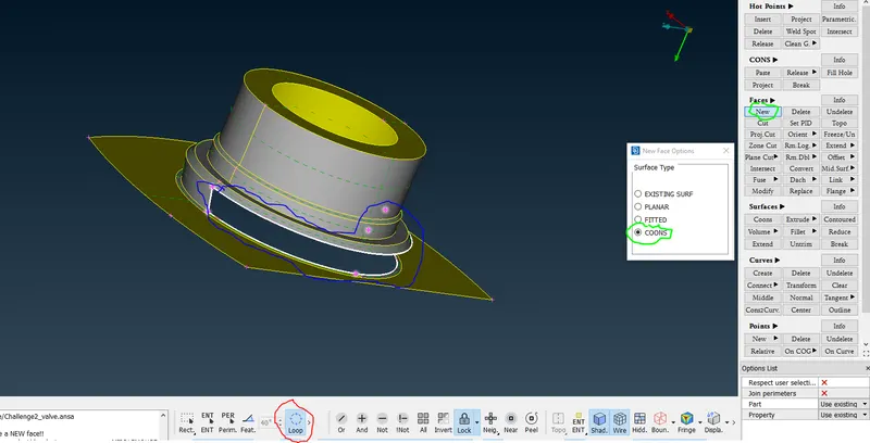
Select New under Faces in TOPO, a New Face Options window pops up where we select COONS and then by using Loop we select edges where a new surface has to be created.
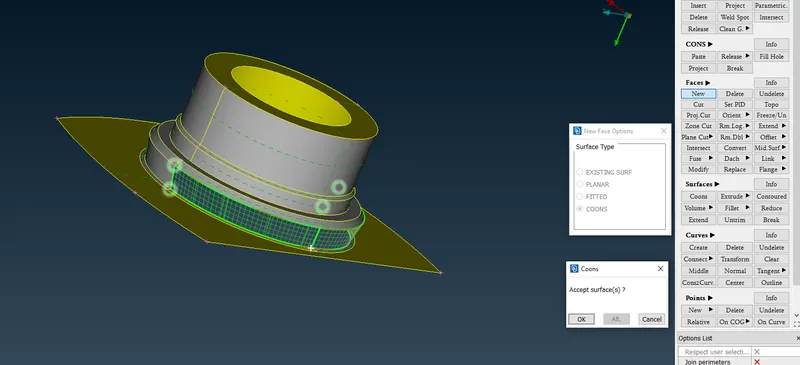
After clicking the middle mouse button / scroll a temporary surface is highlighted to know how the surface will be generated at the selected red cons. If we find the surface generated is fine for us we click OK in the Coons window.
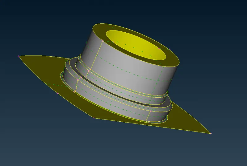
After clicking OK the new surface is generated and the red cons is resolved.
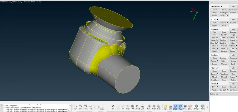
Once the surface is generated and red cons is resolved, remove the Lock and Select All.
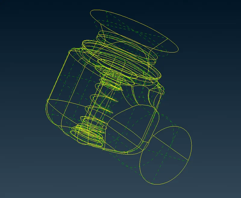
Using Ctrl + Shift we can see that there no red cons present in the geometry.
Now we will be the Geometry Checks using the Check Manager, select the Geometry_Checks by double click.
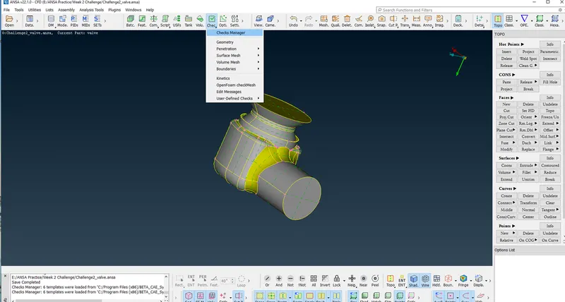
After clicking the Check Manager, the following screen displays
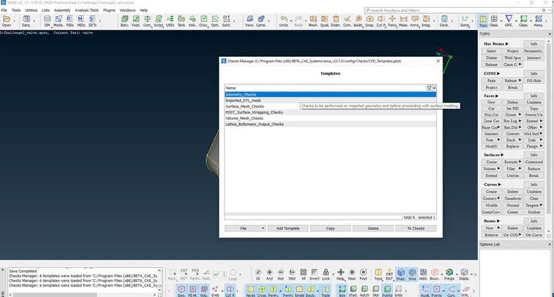
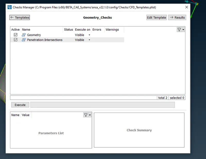
In the above screen press the Execute.
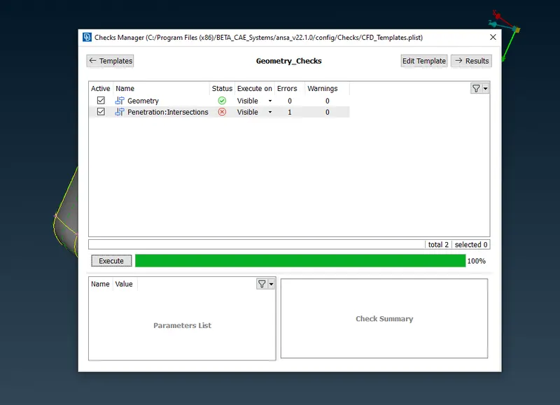
After completing the execution of geometry check one intersection error has been shown and all the geometry has been resolved.
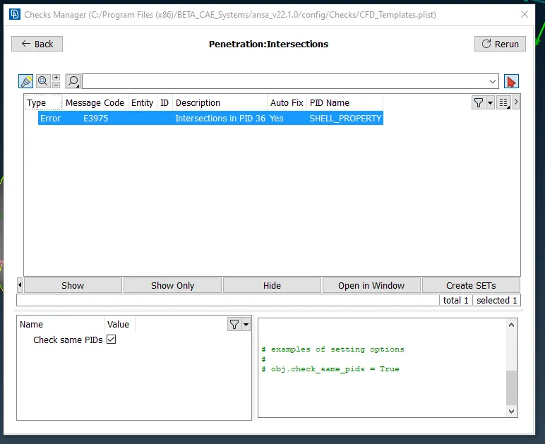
On double clicking Penetraion:Intersections the above screen is displayed.
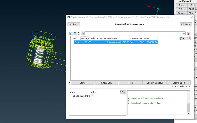
To work on the intersection error which is inside the body we need to isolate the objects involved in the intersection. For us to isolate each part of the assembly we need to assign the PID (Properties ID).
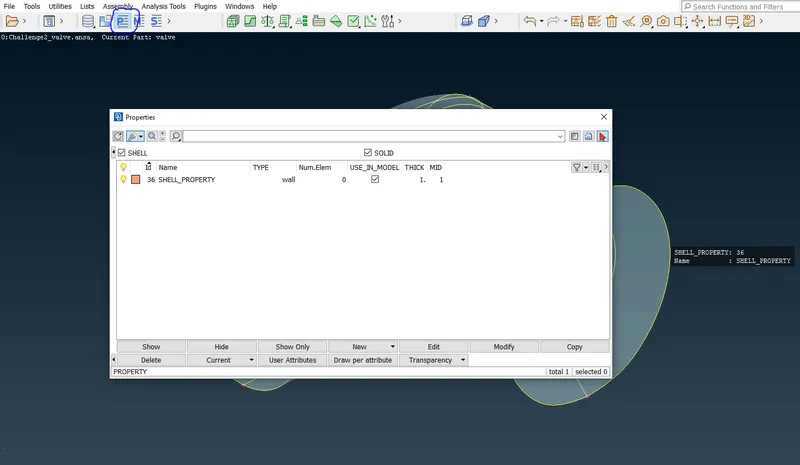
Click on the Properties encircled in blue, the Properties window opens. Now there are two ways to assign PID which are as follows
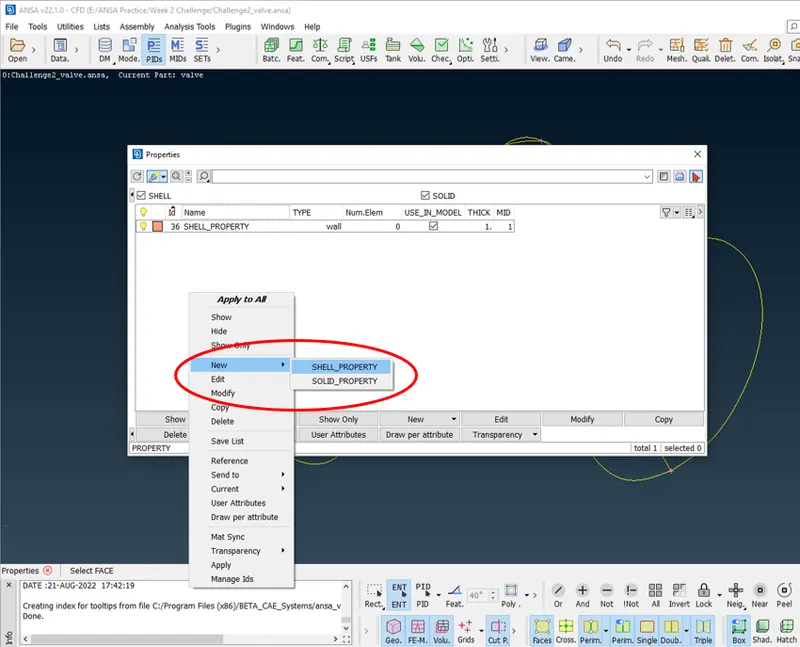
Right click in the properties window and select as shown in the above figure encircled in red.
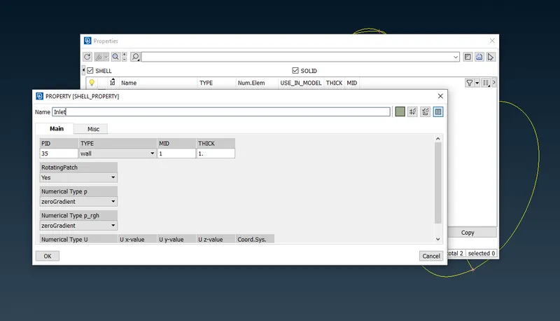
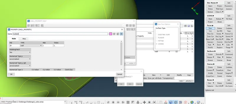
A PROPERTY[SHELL_PROPETY] window opens where we change the Name to Inlet as shown in the above figure. After clicking the OK the below figure is seen where Inlet PID is created but it is still to be assigned.
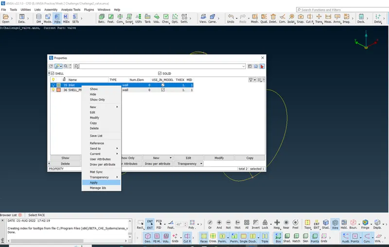
To assign the inlet PID we do the right click by selecting the Inlet PID created and then click the apply.
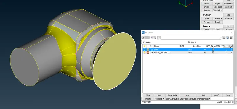
We select the inlet surface by clicking the inlet surface and press the middle mouse button / scroll.
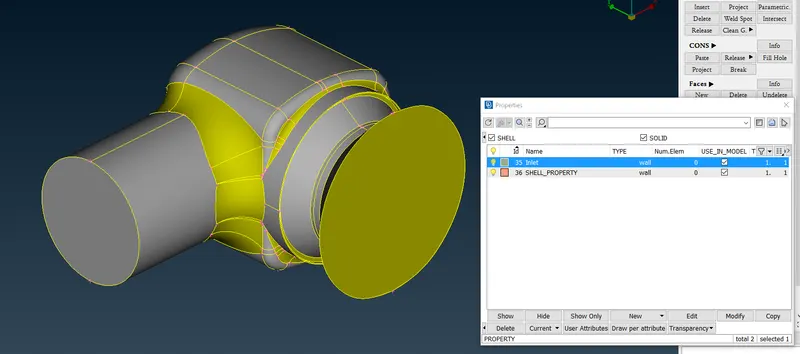
A color change is seen and Inlet PID is assigned. We can notice that the bulb near Inlet PID is on
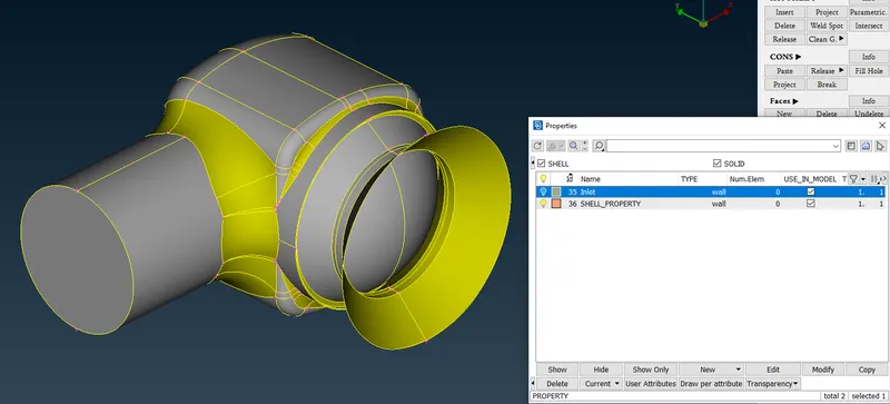
Now can turn on / off inlet surface using the active bulb present in Inlet PID
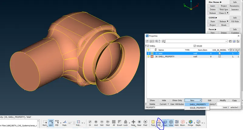
The geometry has been changed to PID mode using the blue encircled option in the image. Also another method to assign a PID is shown in the above figure where we click on the New button present at the bottom of Properties window and then click SHELL_PROPERTY
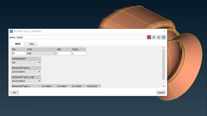
A PROPERTY[SHELL_PROPETY] window opens where we change the Name to Outlet as shown in the above figure. After clicking the OK the below figure is seen where Outlet PID is created but it is still to be assigned.
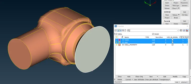
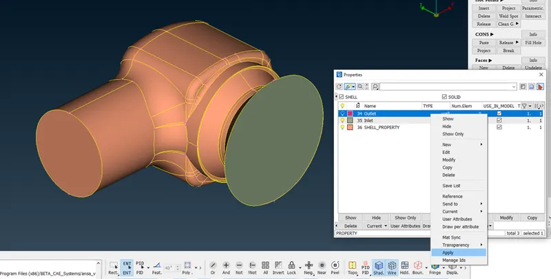
To assign the Outlet PID we do the right click by selecting the Outlet PID created and then click the apply.
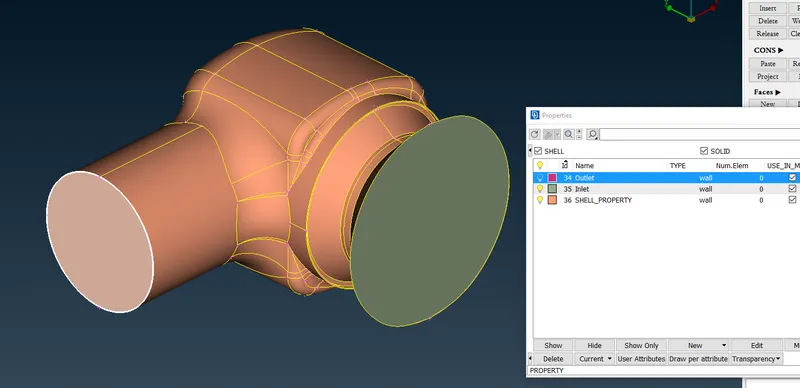
We select the outlet let surface by clicking the outlet surface and press the middle mouse button / scroll.
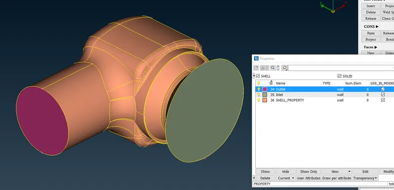
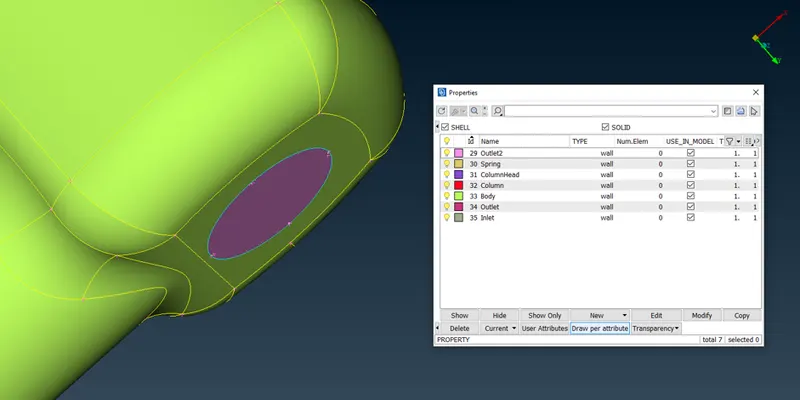
Outlet PID is assigned to the outlet surface as seen in the above figure.
As shown above, we can create the different PID for different components available in the assembly.
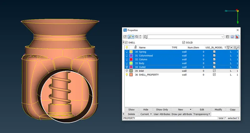
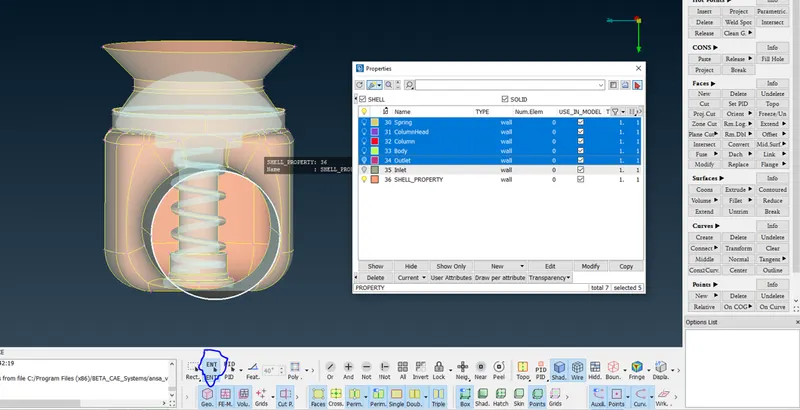
The entire valve is getting selected in entity mode encircled in blue and we are able to isolate the component.
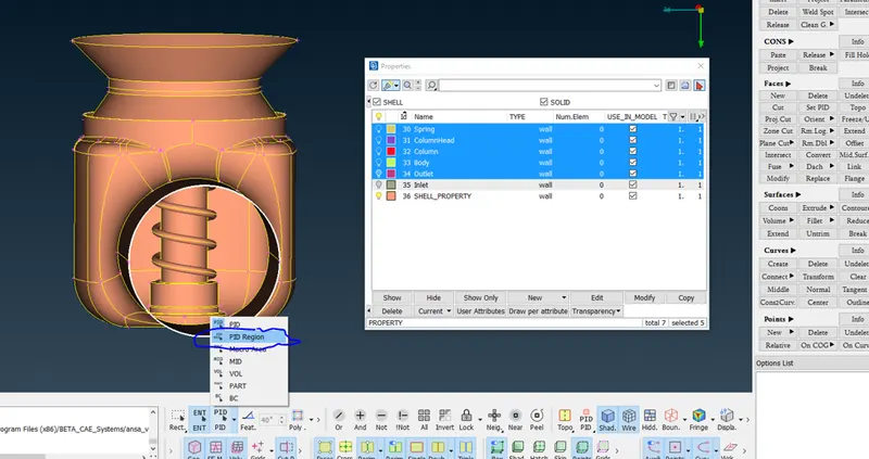
Click on the PID mode as shown in the above figure, select the PID region encircled in blue.
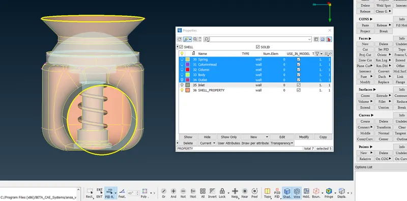
After selecting PID Region and then moving the cursor we see that spring is not selected.
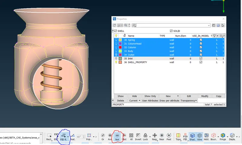
Select Not encircled in red and then select the PID region. move the cursor to the body and then left click the body.
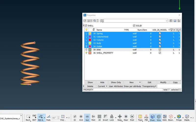
After clicking the middle mouse button / scroll we see that the spring gets isolated nd now we can assign the PID to it.
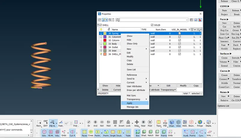
Right Click on the Spring PID, select Apply by left click.
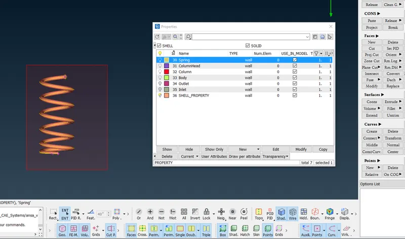
By using the left click and then by draging the cursor we make a selection box as shown in the figure above.
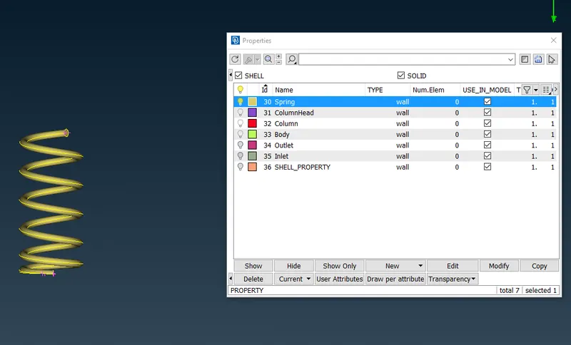
After pressing the middle mouse button / scroll, a PID is assigned to spring we can see it in the above figure where the bulb is glown and the spring colour change is seen.
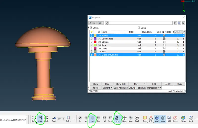
We have isolated the column and column head by using Not in Entity and then Lock the Geometry so that we can isolate the column and column head.
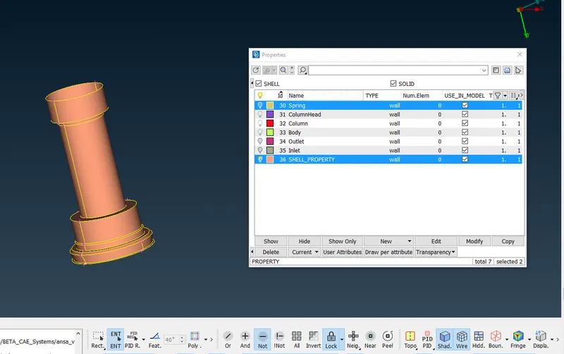
Using Not we have isolated the column as shown above. Now we can assign the Column PID to the geometry seen in the above figure.
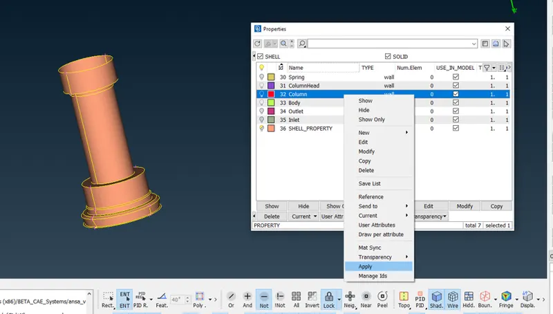
Right Click on the Column PID, select Apply by left click.
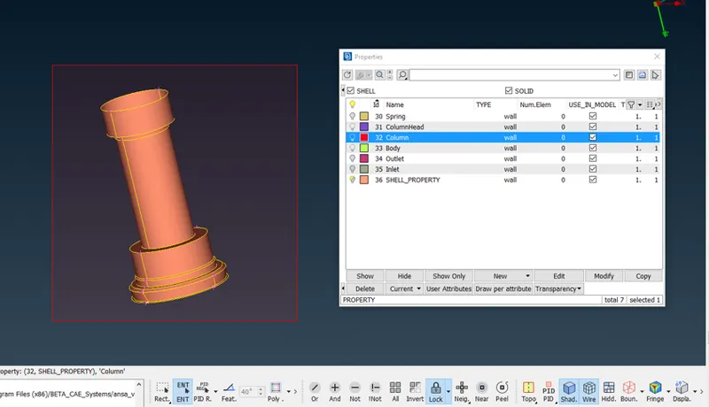
By using the left click and then by draging the cursor we make a selection box as shown in the figure above.
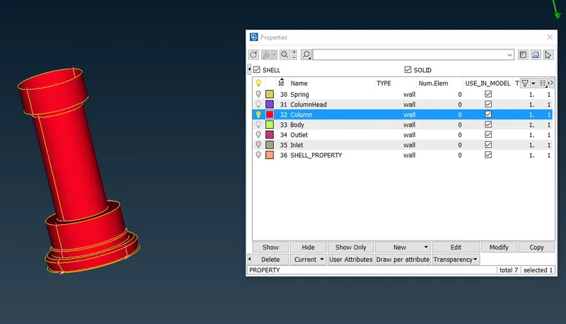
After pressing the middle mouse button / scroll, a PID is assigned to column we can see it in the above figure where the bulb is glown and the column colour change is seen.
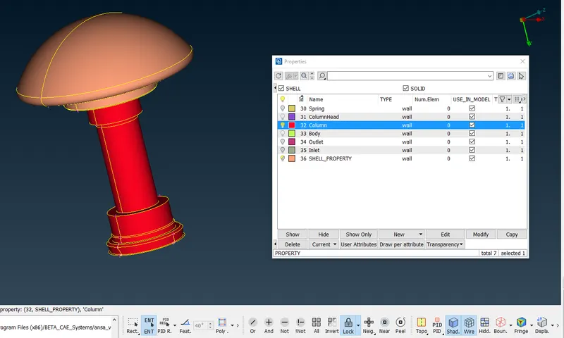
Now we have selected All and we are able to see only the columnand column head since we have used the Lock option.
In the above figure column has been already assigned a PID using the bulb we can hide the column by turning off the bulb.
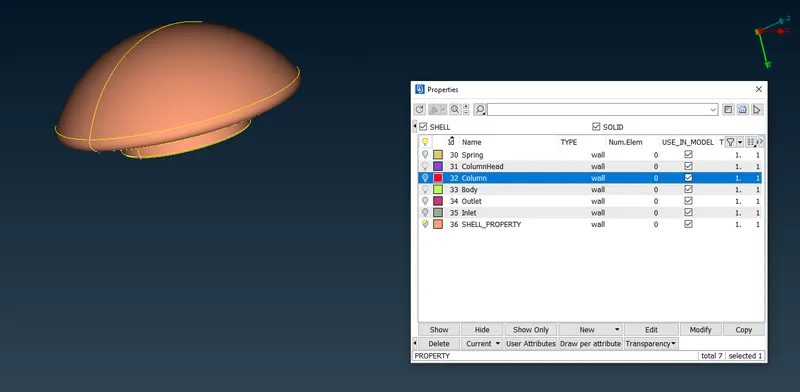
Now our column head is isolated and we can assign the PID for the column head.
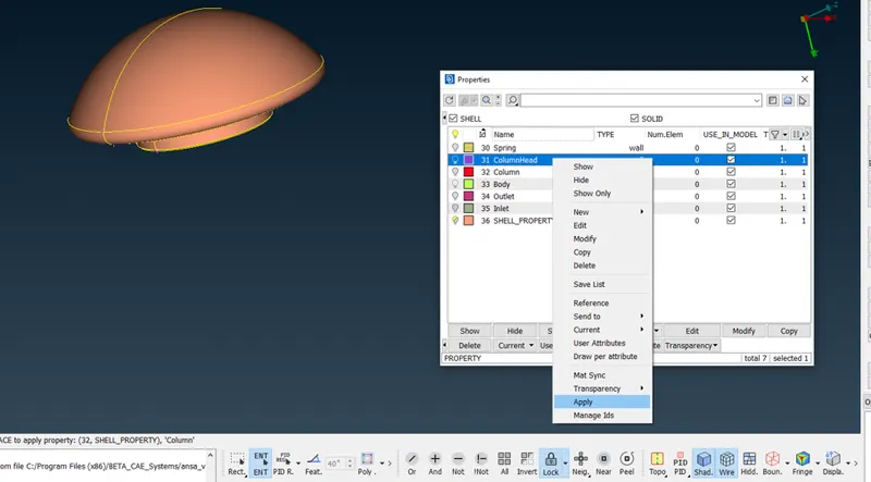
Right Click on the ColumnHead PID, select Apply by left click.
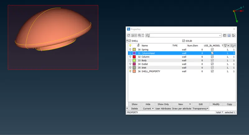
By using the left click and then by draging the cursor we make a selection box as shown in the figure above.
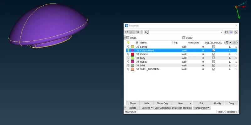
After pressing the middle mouse button / scroll, a PID is assigned to column head we can see it in the above figure where the bulb is glown and the column head colour change is seen.
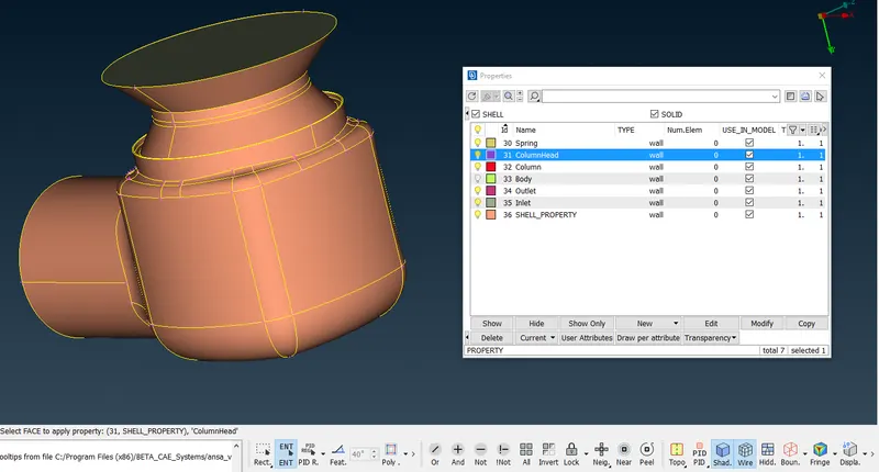
Now removing the lock and selecting the All we get the above figure where every part has been assigned a PID except body.
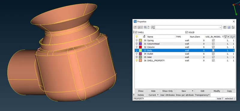
A task to assign the PID to a Body can achieved by isolating the body as shown above.
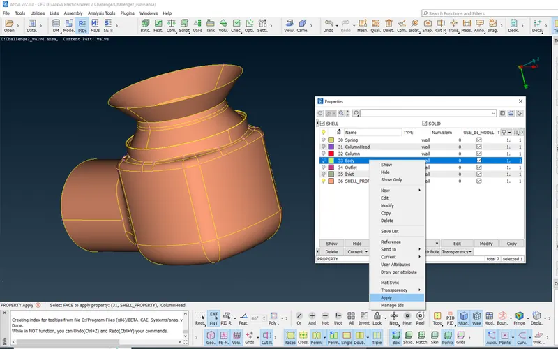
Right Click on the Body PID, select Apply by left click.
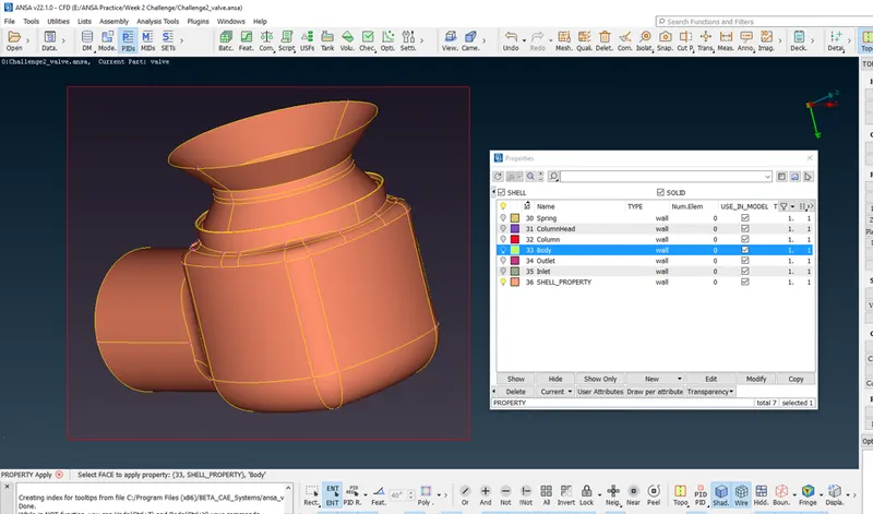
By using the left click and then by draging the cursor we make a selection box as shown in the figure above.
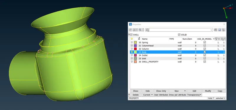
After pressing the middle mouse button / scroll, a PID is assigned to body we can see it in the above figure where the bulb is glown and the body colour change is seen.
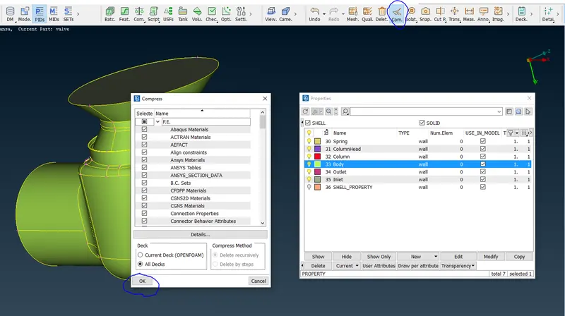
Click the Com., a new window pops up, in that we click OK encircled in blue colour.
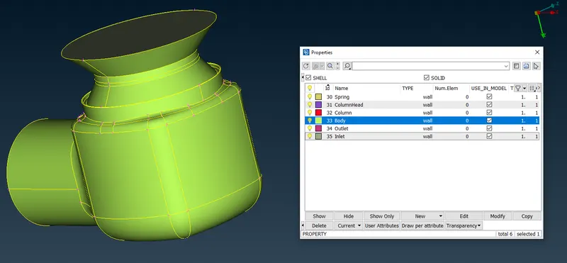
After clicking Ok we see that SHELL_PROPERTY PID vanishes.
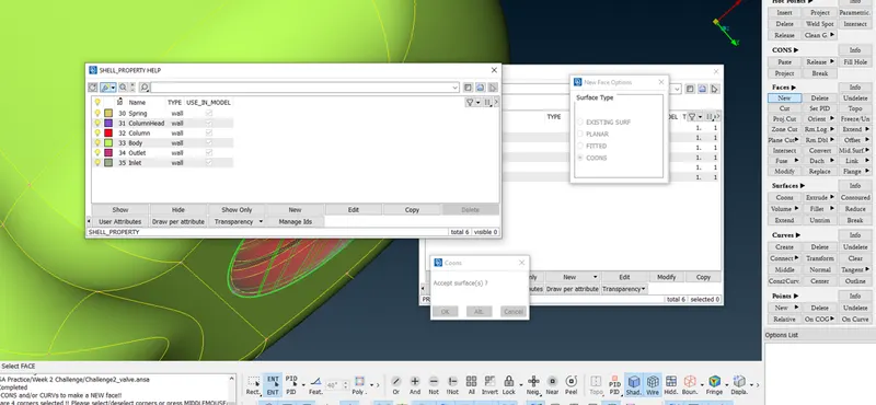
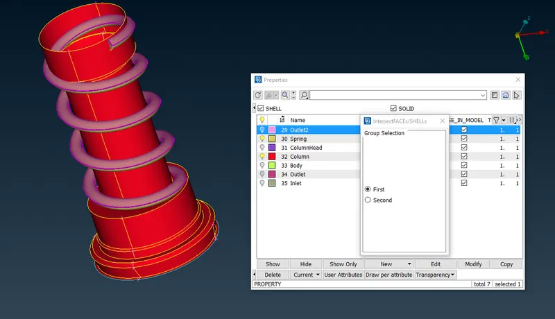
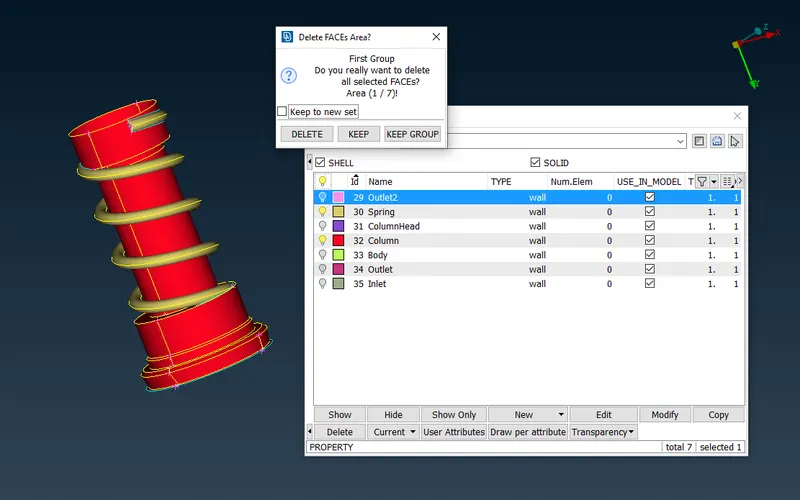
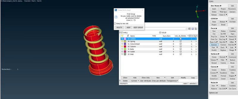
We delete the first surface
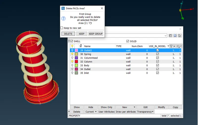
We keep the second surface
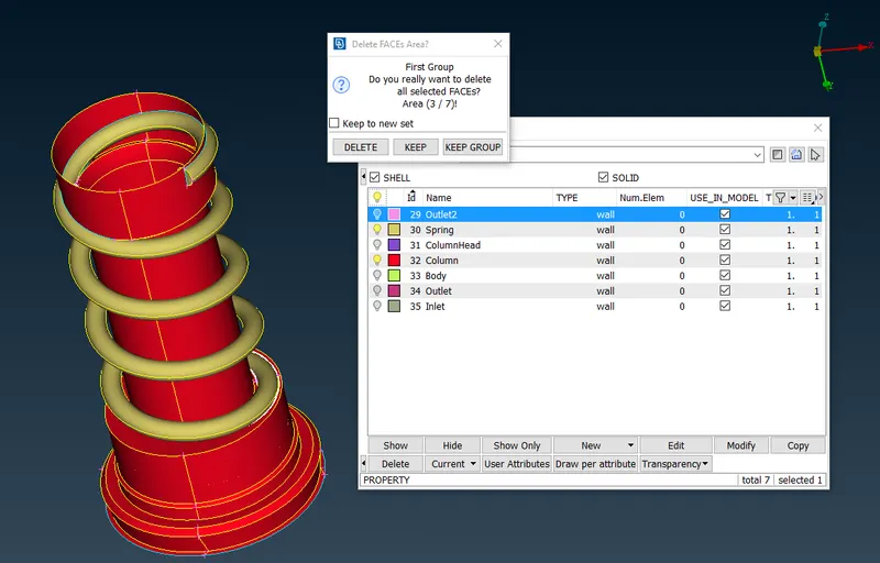
We delete the third surface.
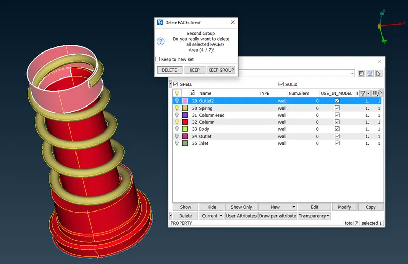
We keep the fourth surface.
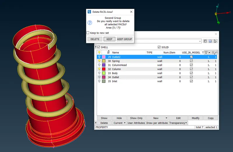
We delete the fifth surface.
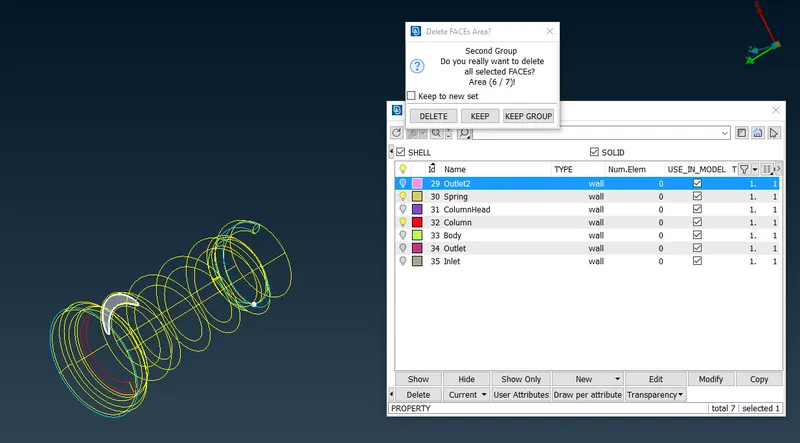
We delete the sixth surface .
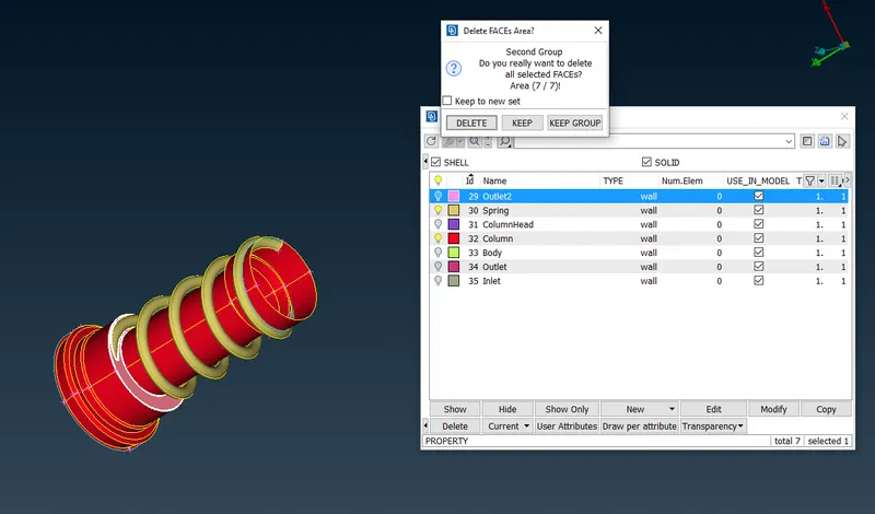
We keep the seventh surface
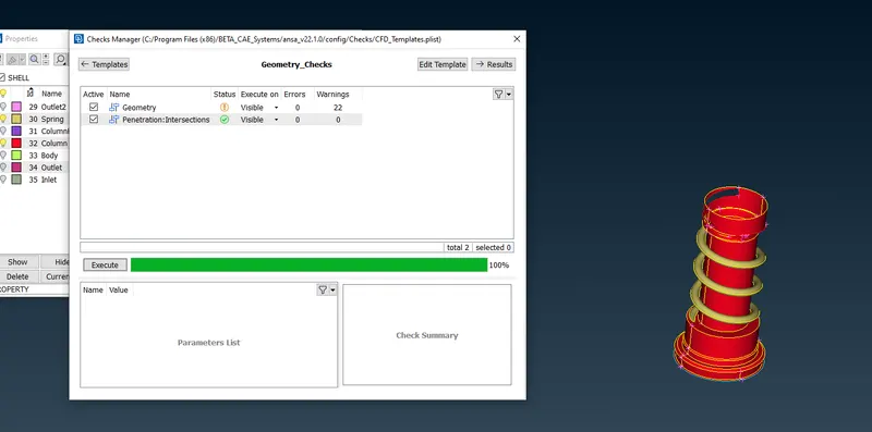
Here we remove the warnings except for 4 warnings which were due to Tripe cons by the following procedure.
Trim the spring just before the intersection with the colum using Cut option. Once the cut is created we delete the faces of the spring that are not required or intersecting with the column. Using Fill Hole create the surface at the end of the spring where cut is generated.
Repeat the procedure at both end of the spring. After that using Fill Hole create a surface in column where the spring was intersecting at the column.
Now warning red cons were present at the top of the column near the column head. Over there we created the curves and the added the hot points. After that the faces or surfaces which were giving these warnings were deleted and new faces were generated.
Once this was done we did the Geometry Check where we found 4 warnings due to Triple Ccons present at the bottom near Outlet2 which was unavoidable.
After that we started Meshing as per the three cases stated in the beginning of the report.
Case 1: Target Length = 5 mm
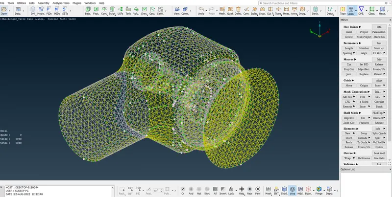
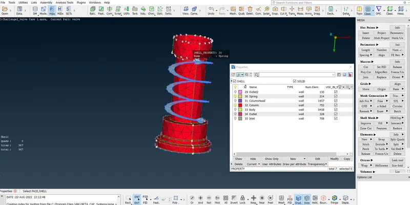
In this case the springs seems to be flattened.
Case 2: Target Length = 3mm
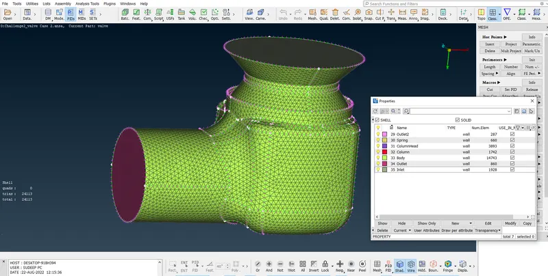
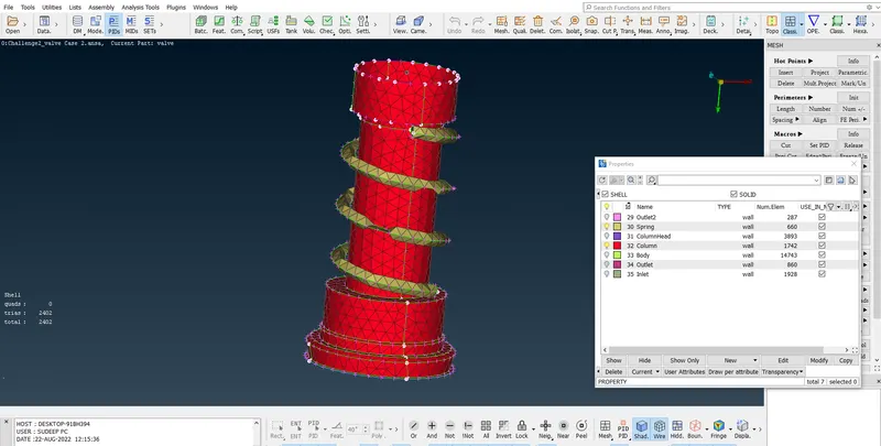
In this case somewhat shape of the spring is recognized.
Case 3 : Target Length = 1mm
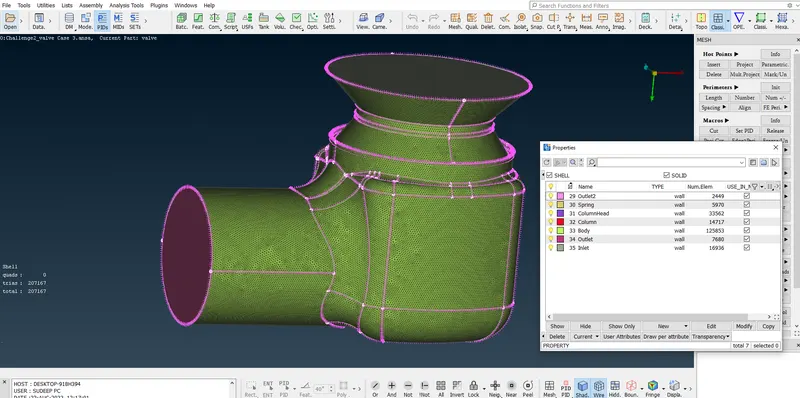
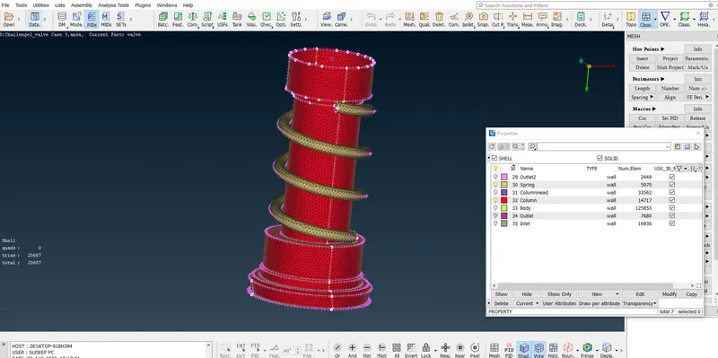
In this case the spring seems to have a perfect shape.