Week 9 - Parametric study on Gate valve.
Aim: To perform a parametric study on the gate valve simulation by setting the opening from 10 % to 80%.
ABSTRACT:
Performing a parametric study on the gate valve simulation by setting the opening from 10 % to 80%. Obtain the mass flow rates at the outlet for each design point. Calculating the flow coefficient and flow factor for each opening and plot the graph. Discussing the results of the mass flow rate and flow coefficient.
Introduction:
Gate Valve:
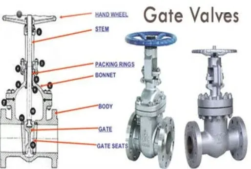
A gate valve, also known as a sluice valve, is a valve that opens by lifting a barrier (gate) out of the path of the fluid. Gate valves require very little space along the pipe axis and hardly restrict the flow of fluid when the gate is fully opened. The gate faces can be parallel but are most commonly wedge-shaped (in order to be able to apply pressure on the sealing surface).
Gate valves are used to shut off the flow of liquids rather than for flow regulation, which is frequently done with a globe valve. When fully open, the typical gate valve has no obstruction in the flow path, resulting in very low flow resistance. The size of the open flow path generally varies in a nonlinear manner as the gate is moved. This means that the flow rate does not change evenly with stem travel. Depending on the construction, a partially open gate can vibrate from the fluid flow.[1]
The following construction or Parts of Gate Valve:
- Body
- Bonnet
- Disc
- Seat
- Stem and
- Manual actuators [2]
Flow coefficient :
The flow coefficient of a device is a relative measure of its efficiency at allowing fluid flow. It describes the relationship between the pressure drop across an orifice valve or other assembly and the corresponding flow rate.
Mathematically the flow coefficient Cv (or flow-capacity rating of valve) can be expressed as :

where:
- Q is the rate of flow (expressed in US gallons per minute),
- SG is the specific gravity of the fluid (for water = 1),
- ΔP is the pressure drop across the valve (expressed in psi).
Flow factor :
The kV-factor for a given valve is a constant which in a simple way states the valve capacity. The kV-factor is determined by the valve manufacturer by experiments. The kV factor specifies the water flow in m3 through the valve in one hour at a pressure drop across the valve of 1Bar
The metric equivalent flow factor (Kv) is calculated using metric units.

where,
- Kv is the flow factor (expressed in m3·h−1).
- Q is the flowrate (expressed in cubic metres per hour m3·h−1),
- SG is the specific gravity of the fluid (for water = 1),
- ∆P is the differential pressure across the device (expressed in bar).
Kv can be calculated from Cv using the equation,

The kv factor or value as it is also called is defined in VDI/VDE Richtlinien No. 2173. A simplified version of the definition is: The kv factor of a valve indicates "The water flow in m3/h, at a pressure drop across the valve of 1 kgf/cm2 when the valve is completely open.
PRE-PROCESSING :
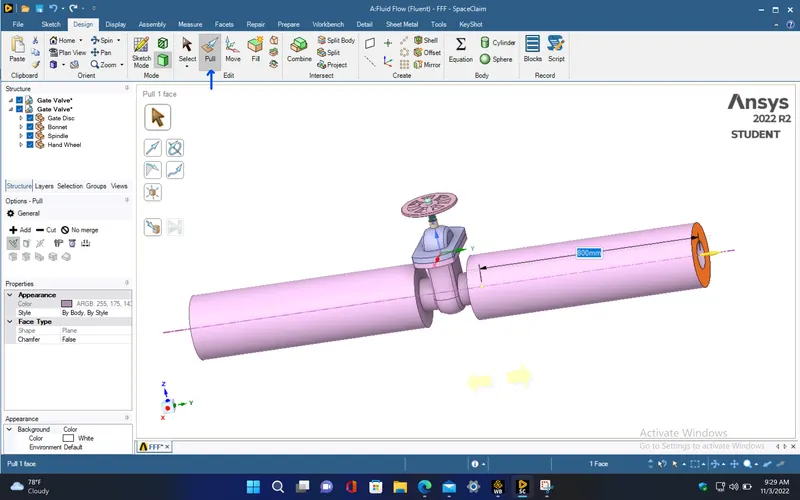
- Import the given gate valve model into spaceclaim and use the pull tool to extend either sides of the valve pipe to 800mm.
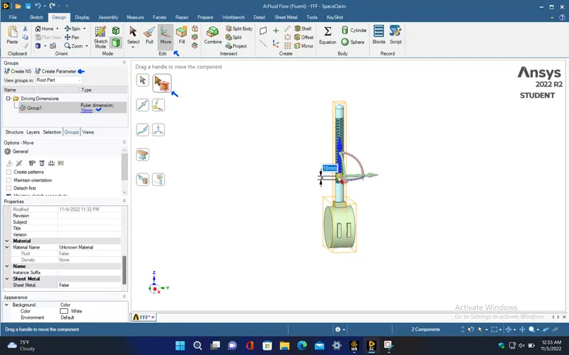
- To provide gate valve lift, isolate the gate disc and spindle, and move those components to 10mm in positive z-direction using move tool under design tab. Now, click the Create parameter option under Groups tab to create it as the input parameter for the simulation.
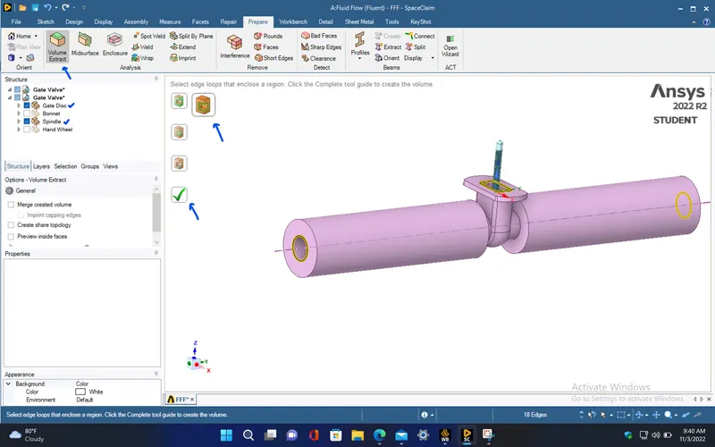
- Hide the bonnet and hand wheel, and use Volume Extract option under Prepare tab to extract the fluid volume by selecting the edges of the fluid domain in the gate valve model.
- Make sure that the fluid volume is extracted properly and also the lift of the gate valve is set to 10mm.

- The inner diameter of the valve pipe in which the fluid is flowing, is measured to be 100mm. So, for 10% to 80% of the gate valve opening, the lift of the gate valve which is given as the input parameter, is to be taken from 10mm to 80mm with 10mm increment. Now, close the spaceclaim.[3]
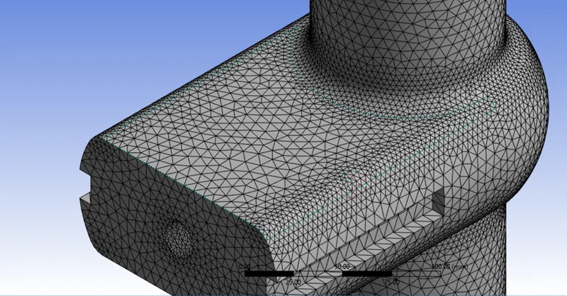
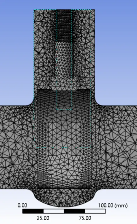
Now, open the mesh and generate the mesh with 7mm and give the named selection for the geometry.
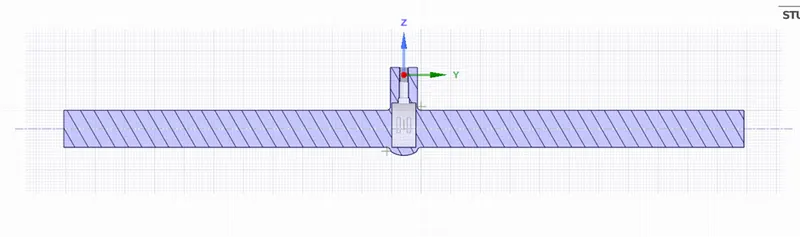
PART-A
Case 1)
Height = 10 mm
Nodes= 64300
elements= 314661
Geometry of the gate valve with 10mm height.
Meshing of the geometry.
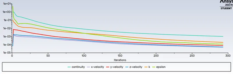
Now doing the simulations of the geometry and doing the standard initilazation computing it from the inlet.
Residuals:
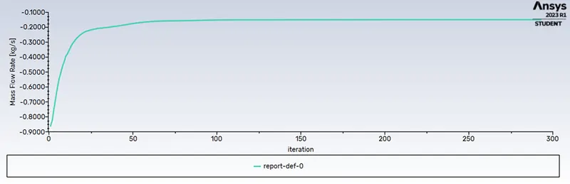
Mass flow rate at the outlet:
Velocity contour of water flowing in the gate valve:
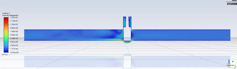
Mass flow rate = -0.14958 kg/s
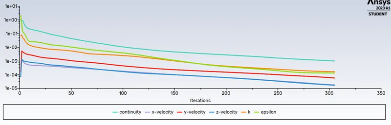
Case 2)
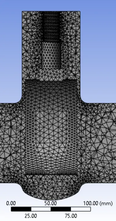
Height = 20 mm
Nodes= 64131
elements= 314402
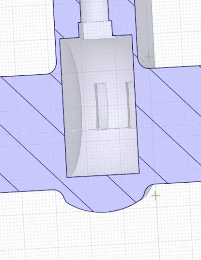
Geometry of the gate valve with 20mm height.
Meshing of the geometry:
Residuals:
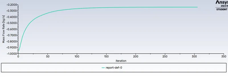
Mass flow rate at the outlet:
Velocity contour of water flowing in the gate valve:
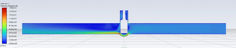
Mass flow rate = -0.23845 kg/s
Case 3)
Height= 30mm
Nodes= 64023
Elements= 314100
Geometry of the gate with 30mm
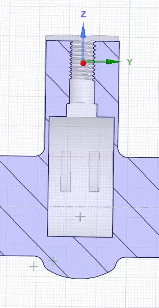
Meshing of the Geometry:
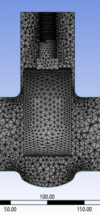
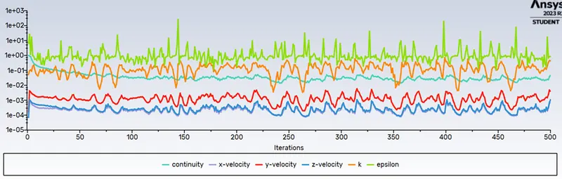
Residuals of the Geometry:
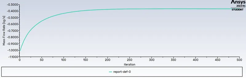
Mass flow rate at the outlet:
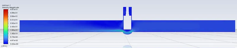
Velocity contour of water flowing in the gate valve:
Mass flow rate = -0.36322 kg/s
Case 4)
Height= 40
Nodes= 63799
Elements= 313016
Geometry of the gate with 40mm height.
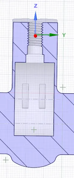
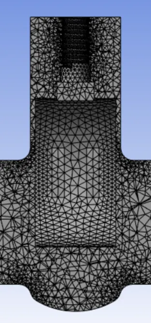
Meshing of the geometry:
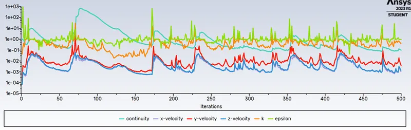
Residuals:
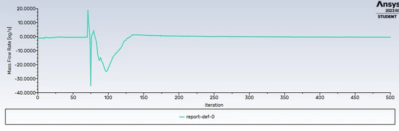
Mass flow rate at the outlet:
Velocity contour of water flowing in the gate valve:
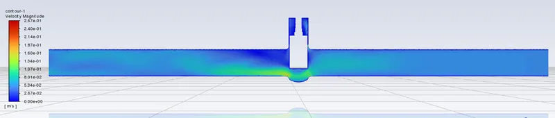
Mass flow rate= -0.39816 kg/s
Case 5)
Height = 50mm
Nodes= 63581
Elements= 311773
Geometry of the gate with 50mm height.
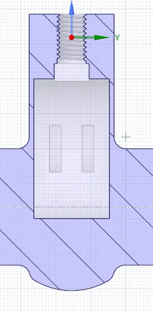
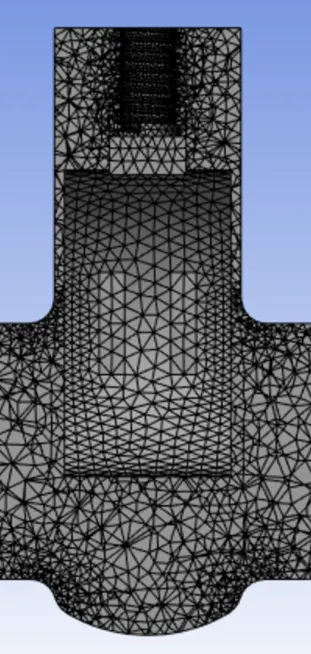
Meshing of the geometry:
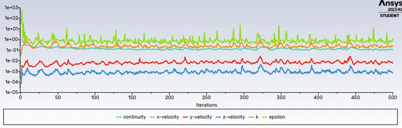
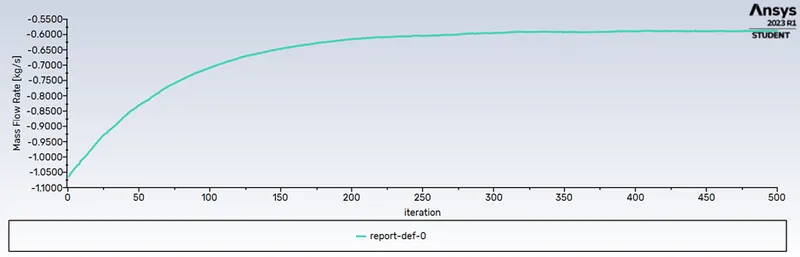
Residuals:
Mass flow rate:
Velocity contour of water flowing in the gate valve:
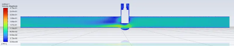
Mass Flow rate: -0.58762 kg/s
Case 6)
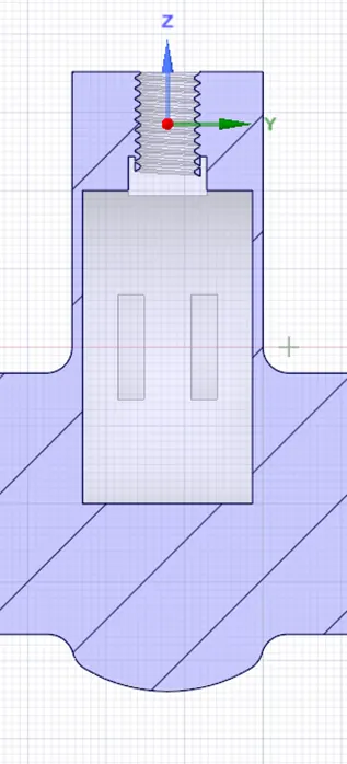
Height: 60mm
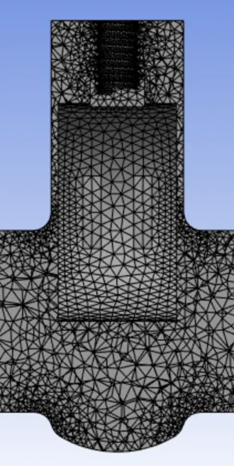
Nodes: 63267
Elements: 309905
Geometry of the gate with 60mm height:
Meshing of the geometry:
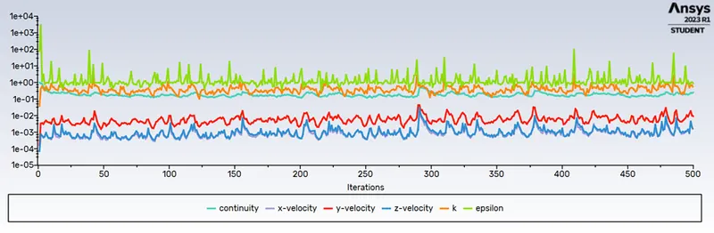
Residuals:
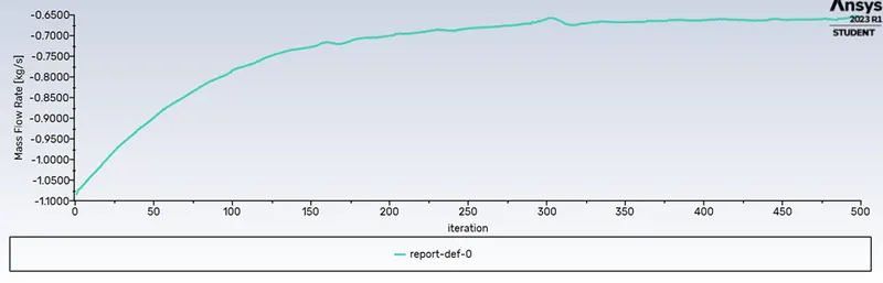
Mass flow rate at the outlet:
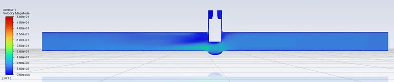
Velocity contour of water flowing in the gate valve:
Mass flow rate= -0.65496 kg/s
Case 7)
Height = 70mm
Nodes= 62955
Elements = 307378
Geometry of the gate with 70mm height:
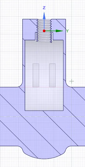
Meshing of the geometry:
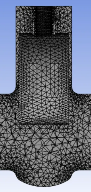
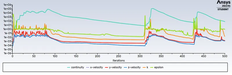
Residuals:
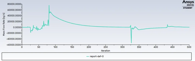
Mass flow rate at the outlet:
Velocity contour of water flowing in the gate valve:
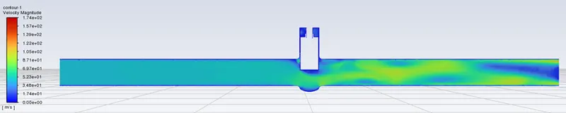
Mass flow rate: -0.7259 kg/s
Case 8)
Height = 80mm
Nodes = 67586
Elements= 329742
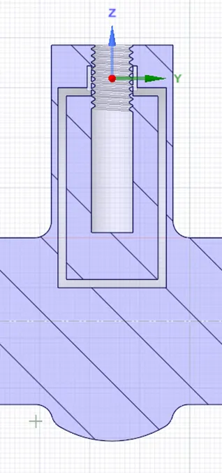
Geometry of the gate with 80mm height:
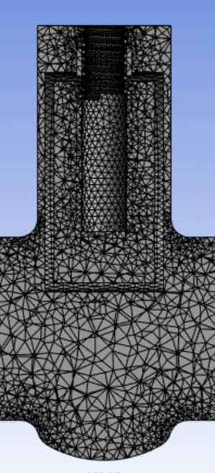
Meshing of the geometry:
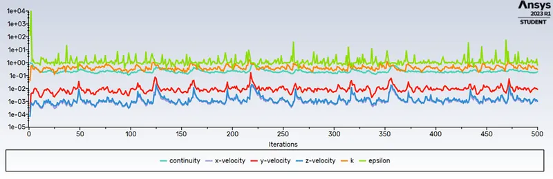
Residuals:
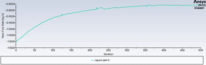
Mass flow rate at the outlet:
Velocity contour of water flowing in the gate valve:
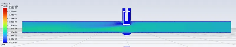
Mass flow rate= -0.80636 kg/s
PART-B
Calculating the flow coefficient:
Relative measure of its efficiency at allowing fluid flow is called flow coefficient.
`C_v=Qsqrt((SG)/(DeltaP))`
Q= rate of flow
SG= Specific gravity
`Deltap`=Pressure drop across valve
Q=mass flow rate/density
`Q=m_s/rho`
Based upon the above mentioned formula we will be finding the Flow Coefficient.
density of the water is `1(kg)/(mm)^3`
specific gravity of water is `0.001(kg)/(mm)^3`
Pressure drop in Bar is 0.9999 bar
| `M_s`(kg/s) | `rho`(kg/mm^3) | `Q_s`(mm3/s) | SG(kg/mm3) | `DeltaP`(bar) | `C_v` |
| 0.14958 | 1 | 0.14958 | 0.001 | 0.9999 | 0.0047 |
| 0.23845 | 1 | 0.23845 | 0.001 | 0.9999 | 0.0075 |
| 0.36322 | 1 | 0.36322 | 0.001 | 0.9999 | 0.0114 |
| 0.39816 | 1 | 0.39816 | 0.001 | 0.9999 | 0.0125 |
| 0.58762 | 1 | 0.58762 | 0.001 | 0.9999 | 0.0185 |
| 0.65496 | 1 | 0.65496 | 0.001 | 0.9999 | 0.0206 |
| 0.7259 | 1 | 0.7259 | 0.001 | 0.9999 | 0.0229 |
| 0.80636 | 1 | 0.80636 | 0.001 | 0.9999 | 0.0254 |
Now calculating the flow factor:
`k_v=0.865*C_v`
| `C_v` | `k_v=0.865*C_v` |
| 0.0047 | 0.0040 |
| 0.0075 | 0.0064 |
| 0.0114 | 0.0098 |
| 0.0125 | 0.0108 |
| 0.0185 | 0.0160 |
| 0.0206 | 0.0178 |
| 0.0229 | 0.0198 |
| 0.0254 | 0.0219 |
Part-C
- As the height of the gate increases the the value of the mass flow rate increases in negative direction.
- As the flow rate increases the flow coefficient also increases.
References:
[3]:Week 9 - Parametric study on Gate valve. (skill-lync.com)