Week 9 - Parametric study on Gate valve.
Aim : To perform Parametric study on the Gate Valve by varying the lift of the gate disc from the 10 to 80% of the opening and simulate the results.
Objective :
- Obtain the mass flow rates at the outlet for each design point.
- Calculate the flow coefficient and flow factor for each opening and plot the graph.
- Discuss the results of the mass flow rate and flow coefficient.
Theory : 1. Gate Valve
Gate valve work by inserting a rectangular gate or wedge into the path of a flowing fluid. They are operated by a threaded stem wich connects the actutator( generally a hanf wheel or motor) to the stem of the gate. If the valve has a rising stem its position can be seen just by looking at the position of the stem. Agate valve is used to control the flow through lifting and descending the gate. A gate distinct feature is to provide an unobstructed passageway which includes minimal pressure loss over the valve.
When Gate Valve is fully opened there is no restriction to the flow hence pressure drop is comparitavely low. Generally, the valve are fully closed or fully opened as partially open valve will experience vibration which may lead to excessive wear.
Applications of gate valve
- It can be used for oil, gas, slurries, steam and corrosive liquids
- These valves are suitable for high pressure and temperature applications
- These valves cannot be quickly opened or closed
- It requires a large space for installation, operation, and maintenance
- Large torque is needed to open because of large pressure difference across the seat
- Gate valves are used for steam circuits in ships
2. Flow Coefficient :
A Flow Coefficient Cv is a relative measure of the fluid flow efficiency that is a desigining factor that relates pressure drop (△p) acrros the valve with the flow rate (Q)
The Cv is the number of gallons per minute (gpm) that will flow through a valve at a temperature of 60 F with a pressure drop of across the value of 1 psi.

where:
- Q is the rate of flow (expressed in US gallons per minute),
- SG is the specific gravity of the fluid (for water = 1),
- ΔP is the pressure drop across the valve (expressed in psi).
- Flow Coefficient is important in order to select the best valve for specific application.
- It is easy to compare the different valves flow capacity by measuring control valve flow coefficient.
- It assist in selection of the right size control valve for a particular application.
- We can easily understand the valve characteristics by calculating Cv. Therefore, It is easy to determine the effect of valve on the pressure in the system.
3. Flow Factor (Kv) :
Flow Factor is the equivalent of the flow coefficient is based on the SI unit
The SI unit of flow factor is m^3/hr and is calculated from the formula

Procedure :
1. Spaceclaim :Download the geometry of the Gate Valve from the link.
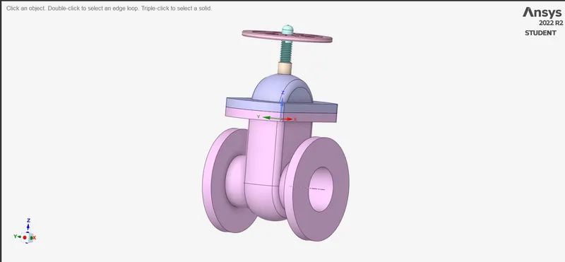
For this challange the main corncern is to see the mass flow rate on the outlet with different lift of the gate valve disc.
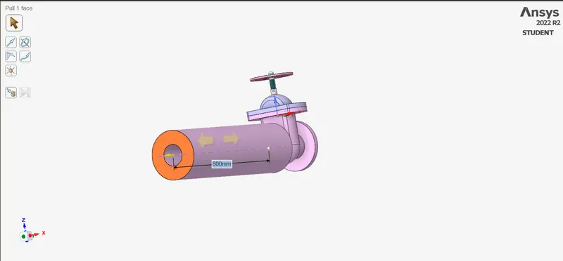
Before extraccting the fluid volume the geometry is short for the flow to get computed properly. So to make sure of that problem we will pull the solid part of the geometry by 800mm on both sides.
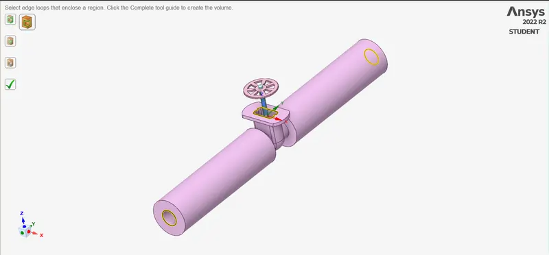
Now we will extract the fluid volume so in this geometry there are 3 edges to select for extraction those are the inlet , outlet and the edge under the bonnet.
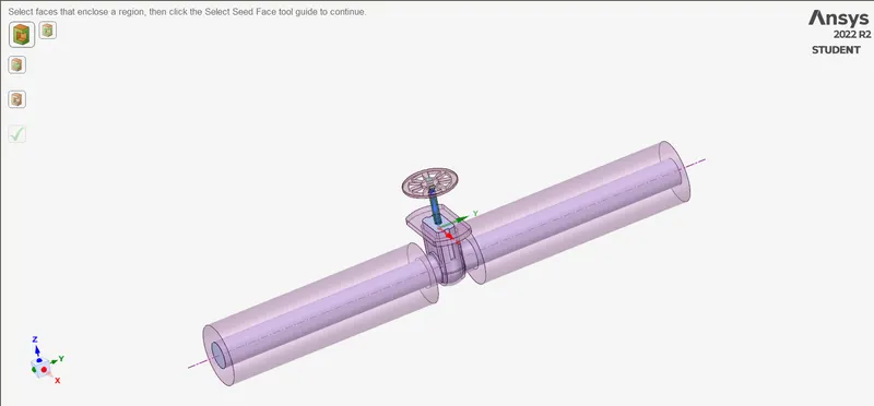
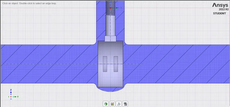
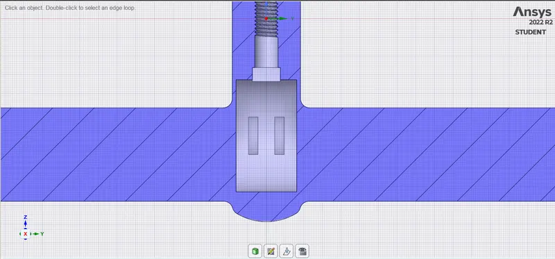
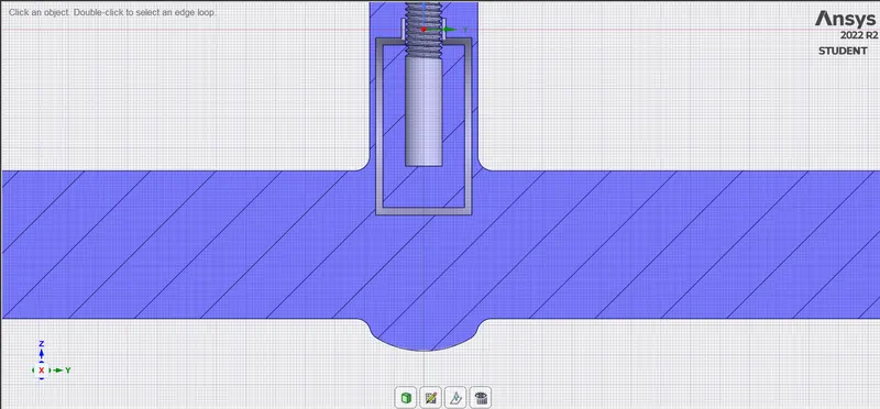
Now to set the lift of the gate disc as the parameter.
- first hide all the parts except the spindle and the gate disc.
- Select the Move option for moving the gate disc.
- Design>Move>Select the move component option>Select the gate disc> big aixs will appear > select the spindle move it a little upwards>Go to group option besides the structure>Create Parameter>
Name it > and the lift is set as a parameter.
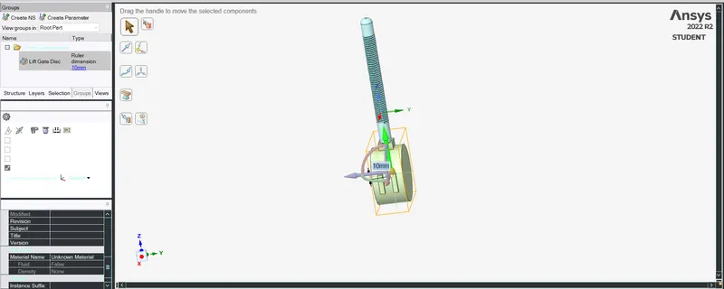
After this supperes the solid parts except the volume.
- to adapt the fluid volume to changes in the solid geometry
- Expand the volume>right click on the expand>and for this challange Update geometry as Context.
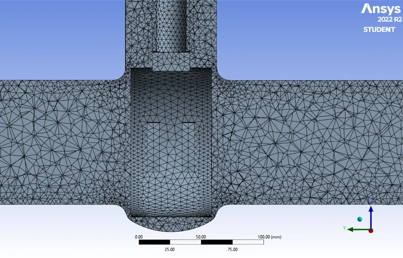
2.Meshing : Name the parts as inlet and outlet
Element Size : 6mm
Number of elements : 415432
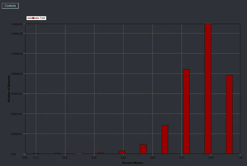
Element Qulaity:
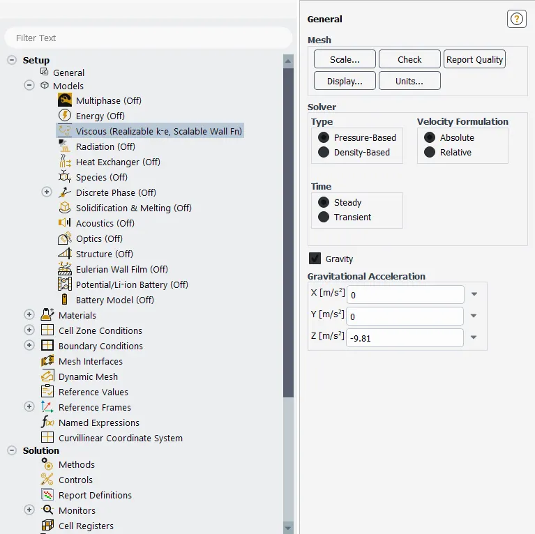
3.Fluent Setup :
- Solver : Pressure-based (as the mach no.> 0.3)
- Velocity formulation : Absolute
- Steady-State
- Gravity : Z = -9.81 m/s^2
- Model : K-Epsilon,Realizable, Scalable wall function
K-epsilon is the most common model is use to simulate mean flow characteristic for the turbulent flow condititons.It is the two equation model that gives a general description of turbulence by means of two transport equation.
The first transported variable is the turbulent kinetic energy (k)
The second transported variable is the rate of dissipation of the turbulent kinetic energy (ε)
This model is usually useful for free shear layer flows with relatively small pressure gradient as well as in confined flows where the Reynolds shear stresses are most important.
Scalable wall function ensure that the wall distance employed in the wall function is such that the y+ > equal to 11.126 irrespective of the level of near-wall grid refinement.
- Materials : water-liquid (h2o)
- Boundary Condidtions : Inlet : pressure-inlet = 10
Define a report for the mass flow rate at outlet and set it as an output parameter
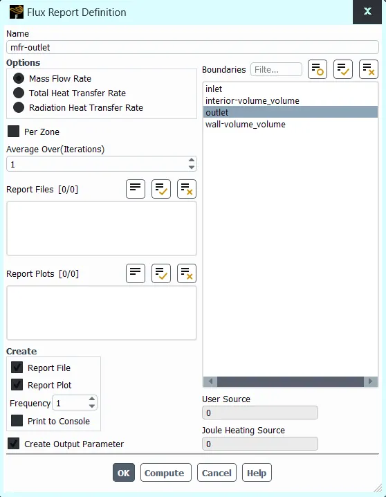
Run the simulation for 500 iteration and plot the results
Calculate the flow coefficient and flow factor and plot the graph for the Cv,Kv V/s Lift of the gate disc.
Results : Part 1 :
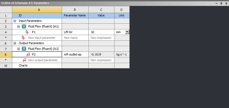
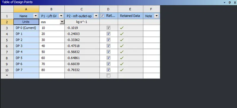 parameter tab with the mass flow rate is shown.
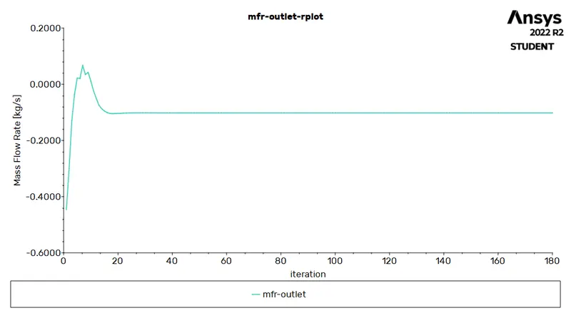
10% lift and mass flow rate results
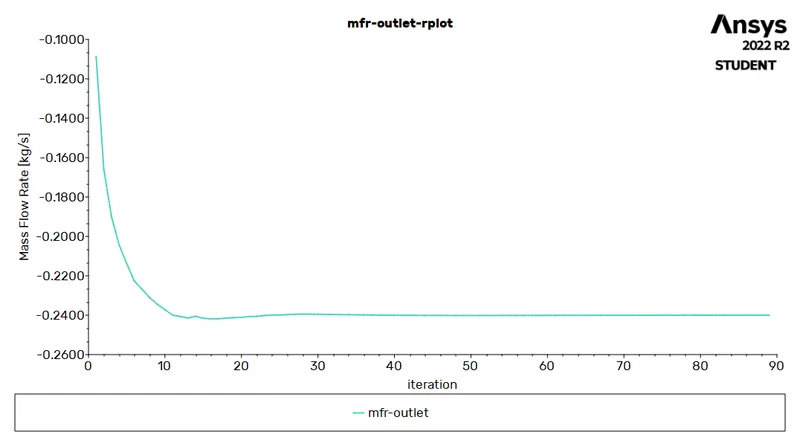
20% lift and mass flow rate results
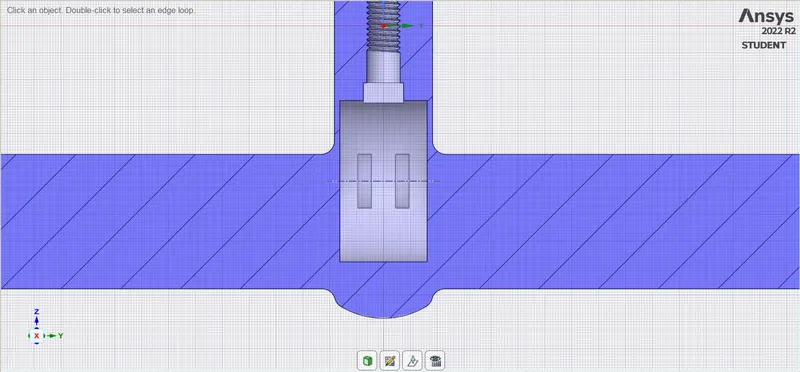
30% lift and mass flow rate results
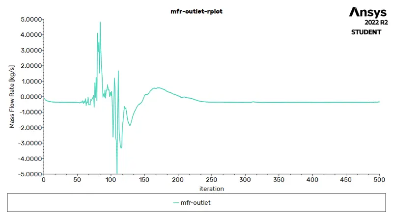
40% lift and mass flow rate results
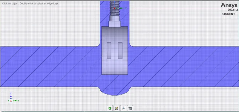
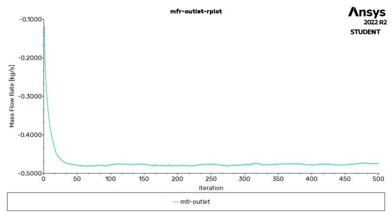
50% lift and mass flow rate results
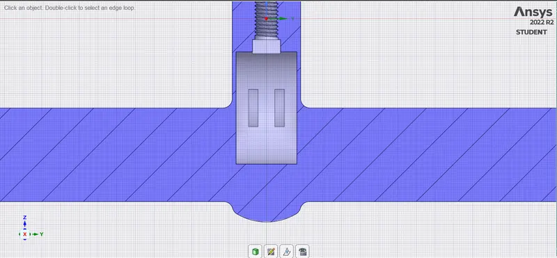
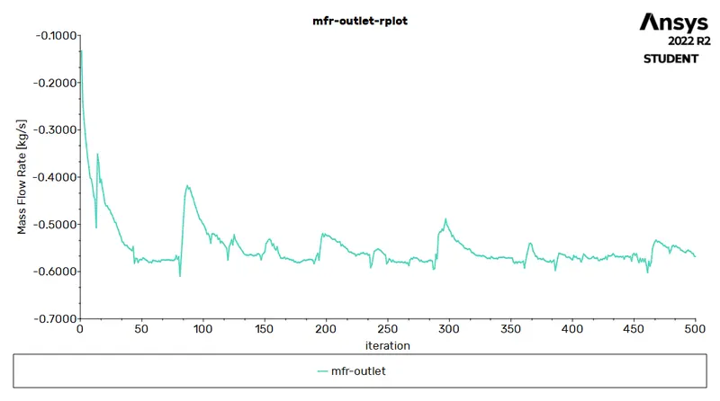
60% lift and mass flow rate results
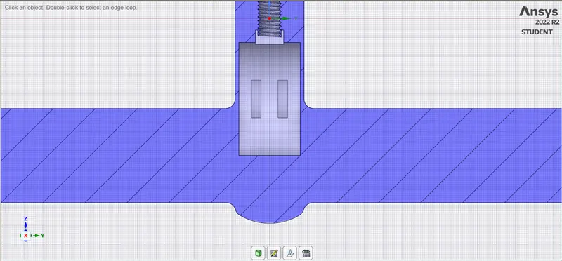
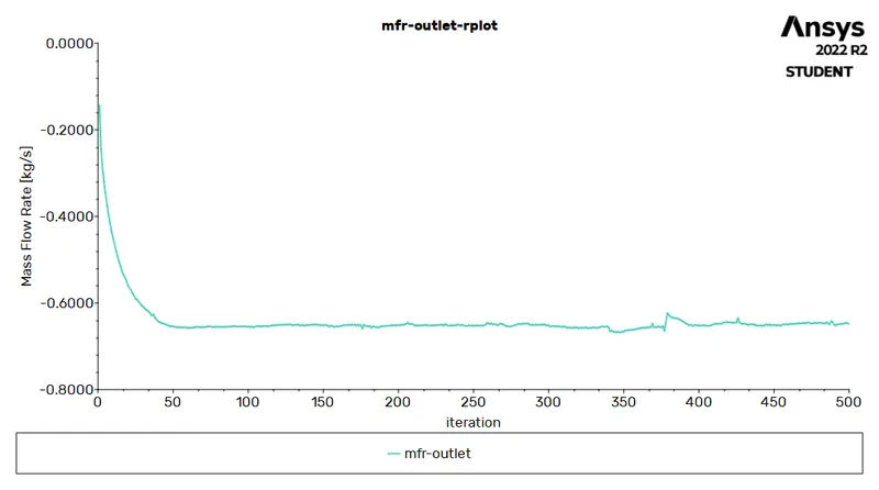
70% lift and mass flow rate results
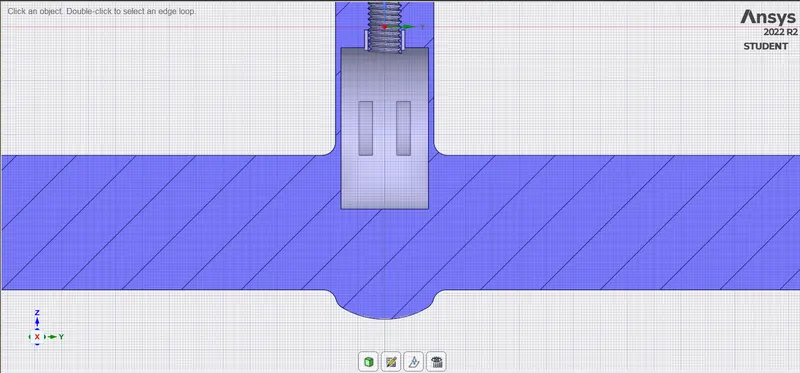
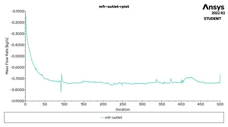
80% lift and mass flow rate results
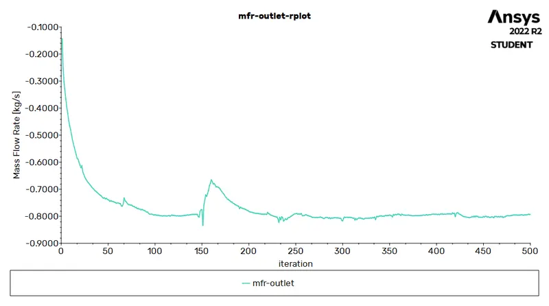
Part 2
Lift mass flow rate Q Q △P △P Specific gravity Cv Kv
(mm) (kg/s) (m^3/s) (gallons/min) Pascal psi water (gpm) (m^3/hr)
10 -0.1019 1.020e-4 1.61 10 0.00145038 1 0.511 0.44
20 -0.24003 2.404e-4 3.81 10 0.00145038 1 1.20 1.03
30 -0.33362 3.342e-4 5.29 10 0.00145038 1 1.67 1.44
40 -0.47518 4.760e-4 7.54 10 0.00145038 1 2.38 2.05
50 -0.56832 5.693e-4 9.02 10 0.00145038 1 2.85 2.46
60 -0.64861 6.497e-4 10.29 10 0.00145038 1 3.25 2.81
70 -0.66039 6.615e-4 10.48 10 0.00145038 1 3.31 2.86
80 -0.79332 7.947e-4 12.59 10 0.00145038 1 3.98 3.44
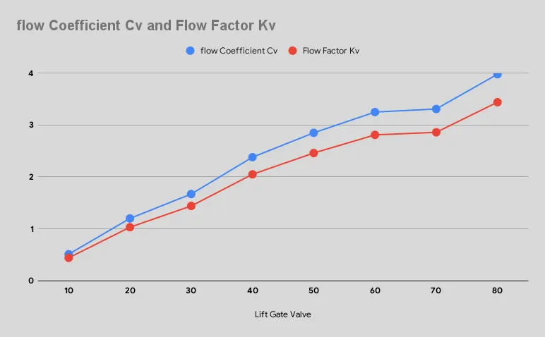
The mass flow rate values are obtained from the fluent and the values of the Cv and Kv are obtained through calculations from the formulas mentioned above. Graph is plotted for the Cv,Kv V/s the gate opening in mm is plotted below.
Conclusion :
- From the graph we can say that the flow coeffficient and flow factor are the function of the gate opening. As the gate opening increses the flow coeffcicient increses as well
- Flow Coeffcient is an important aspect for selection of the specific use of the valve. Depending in the outlet flow and the pressure loss the valve can be selected for the proper use.
- The negative sign in the mass flow rate value indicates the flow is leaving the volume and the mass flow rate also increases as the gate disc rises higher.
- A Parametric study allows you to nominate parameters for the evaluation. We can define parameter range and also can compare the results for each variation.
- Parametric study method saves alot of time in the simulation which require to perform same operations with different inputs or variables for multiple times.