Week 9 - Parametric study on Gate valve.
Aim
Parametric study on Gate valve with varying gate opening length.
Introduction
A gate valve, also known as a sluice valve, is a valve that opens by lifting a barrier (gate) out of the path of the fluid. Gate valves require very little space along the pipe axis and hardly restrict the flow of fluid when the gate is fully opened. The gate faces can be parallel but are most commonly wedge-shaped (in order to be able to apply pressure on the sealing surface).
Gate valves are used to shut off the flow of liquids rather than for flow regulation, which is frequently done with a globe valve. When fully open, the typical gate valve has no obstruction in the flow path, resulting in very low flow resistance. The size of the open flow path generally varies in a nonlinear manner as the gate is moved. This means that the flow rate does not change evenly with stem travel. Depending on the construction, a partially open gate can vibrate from the fluid flow.
Theory
Gate Valve have following parts:-
Bonnet
Spindle
Gate Disc
Hand Wheel
They work togather to tightly close the pathway for fluid (water) in our case when hand wheel rotated controling the gate disc movement. The amount and speed of fluid passing will depend on the gate opening creating high and low pressure regiouns.
Solving & Modelling approach
I have soved through the stages mentioned above with the help of videos shown and guidance of the technical staff.
The process fluesnt fluid flow will be done in following these 5 steps:-
1) Geometry - The geometry of the model will be formed where the actual flow will flow/interfere
2)Mesh - The meshing of the volume is done whoose parameters are set by default with help of 'Boundary Box'
3)Setup - The initial and boundary conditions or parameters and the model choosen are given to the model.
4) Solutions - Based on conditions and requirements the result is calculated with the help of model choosen
5) Results - The final results are appeared here from where the investigation of simulation is done.
Step 0) Download and import the valve model in SpaceClaim
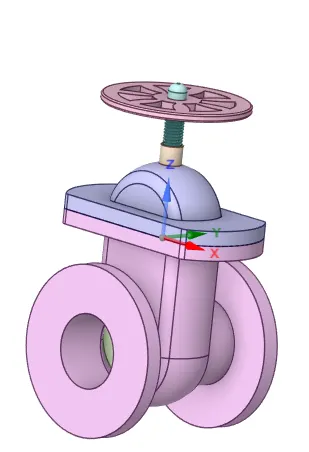
Step 1) Prepare the geometry
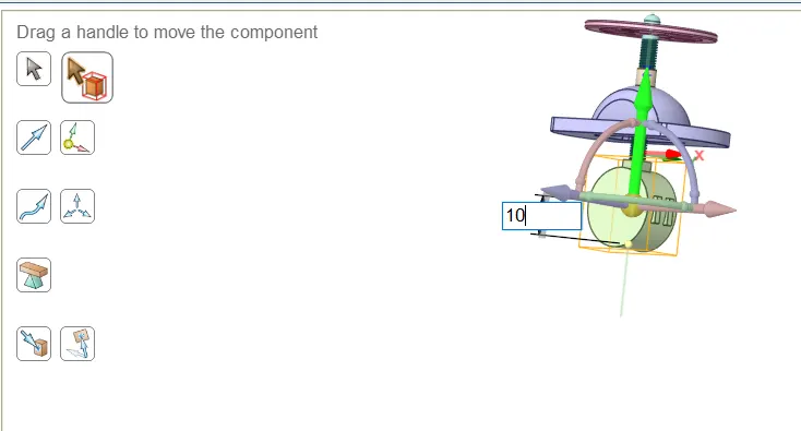
1.1) Move up the valve face
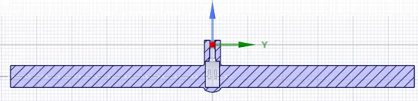
1.2) Pull the inlet/outlet walls to 800mm
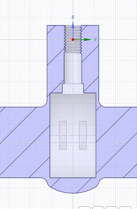
1.3) Extract the volume where fluid should flow
1.4) Don't hide, but surpressfor physics the rest parts
Step 2) Prepare mesh
2.1) Generate mesh

2.2) Assign names to the faces
Pre-processing and solver setting
Step 3) Setup the systems parameters
3.1) Give the physics parameters as given below
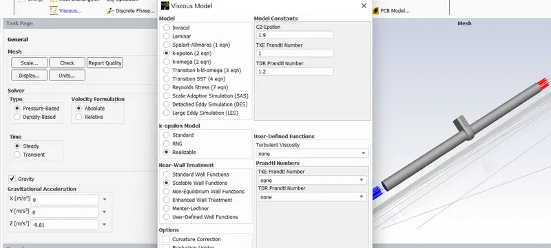
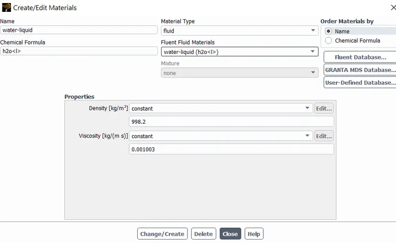
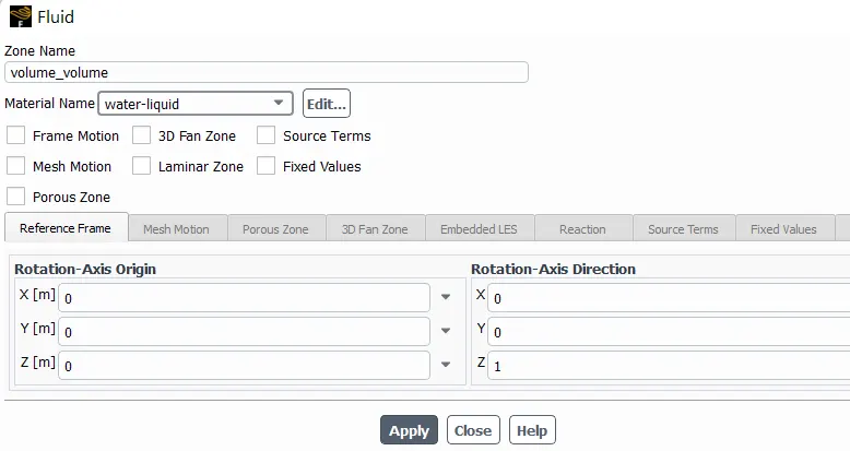
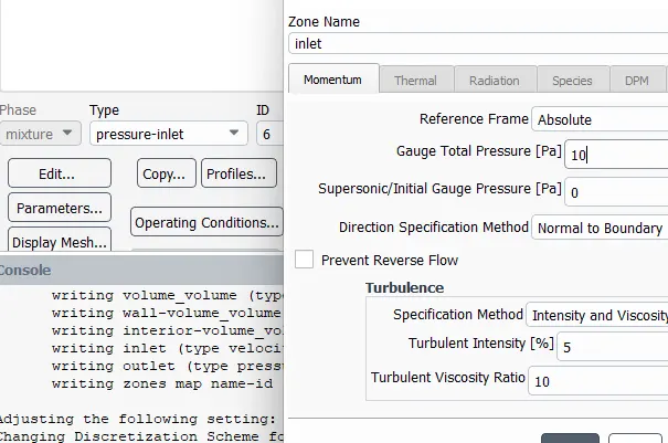
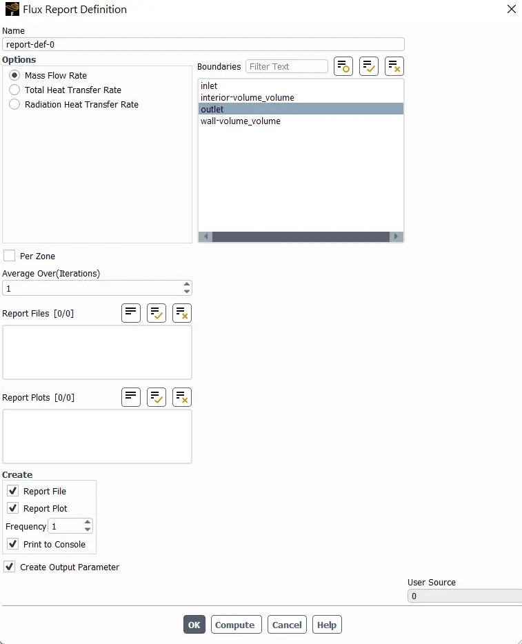
3.2) Define new report for outlet mass-flow and seect 'Create Output Parameter'
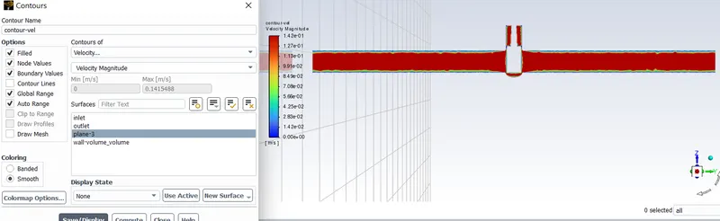
3.3) Create contour on the created plane
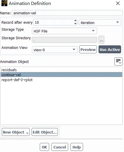
3.4) Write animation for the contour
3.5) Calculate the result for 250 iterations.
Step 4) Create parametric study for our system in Workbench
Results
Following results were obtained:-
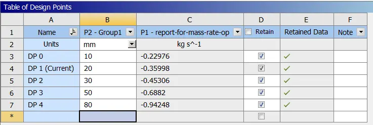
1) Mass flow rate
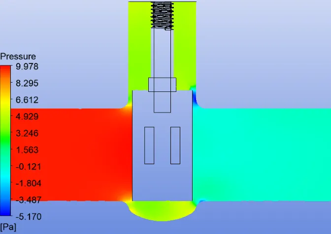
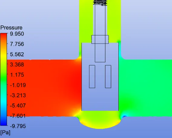
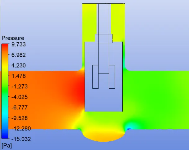
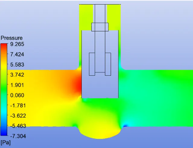
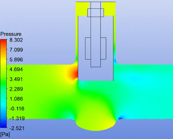
2) Pressure Contour
Case 1) 10mm open
https://drive.google.com/file/d/1ieY2ZMKwQlqVHncXLhlspk-oN8xm_WNk/view?usp=sharing
Case 2) 20mm open
https://drive.google.com/file/d/1_LJB7UBNQ55foF7y0BHnNTkGePa-lImr/view?usp=sharing
Case 3) 30mm open
Case 4) 50mm open
Case 5) 70mm open
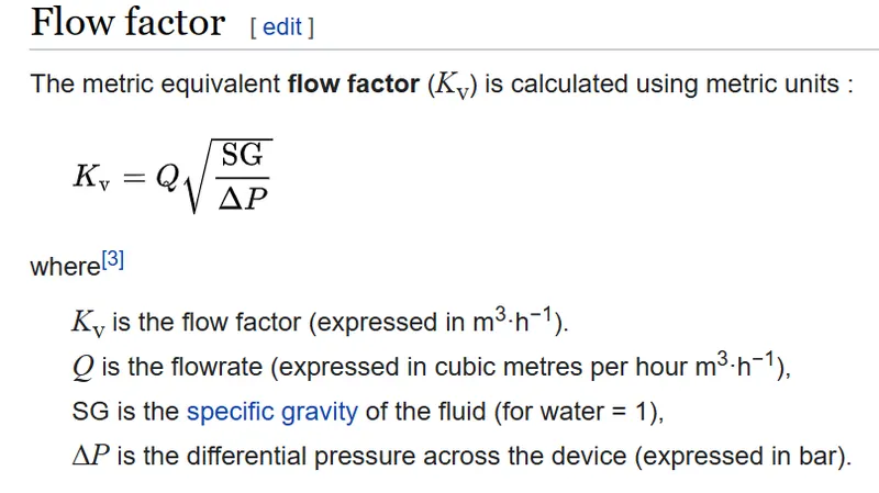
3) Flow Factor
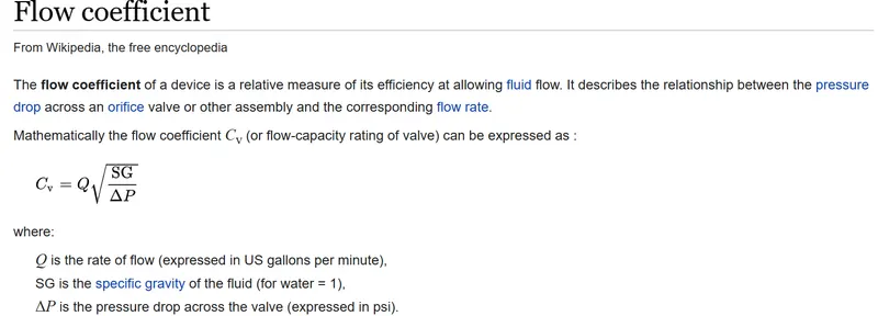
4) Flow Coeff
Q = 1000/mass flow
SG = 1
Case 1
dP = 15.148
Kv = 53.73
Cv = 61.7
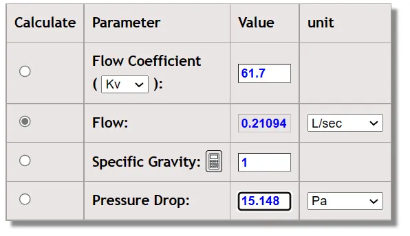
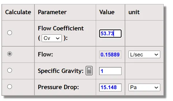
similarly
Case 2
dP = 17.551
Kv = 87.07
Cv = 100.66
Case 3
dP = 24.657
Kv = 156.2
Cv = 135.11
Case 4
dP = 16.569
Kv = 234.55
Cv = 271.66
Case 5
dP = 10.832
Kv = 375.91
Cv = 434.57
Conclusion
The following points can be concluded from the report:-
- We can conclude from observations that velocity in the first case is very low. As opening or lift of the Gate Disc increases, velocity of the flow increases.
- We can observe that at the front or inlet side of the valve, pressure is high. As flow passes through the valve opening, it decreases.
- And at the outlet there are no any restrictions to the flow, so pressure becomes 0.
- It means there is minimum Pressure Drop.
- There is a gradual increase in Mass Rate, Flow Coefficient and Flow Factor as Lift of the Gate Disc increases, or from 10% to 80%, or 10 mm 80 mm.
- When the valve if fully open, Mass Flow rate and Flow Coefficient and Flow Factor becomes maximum.
- Thus, parametric study helps to analyze the different positions of valve opening and gives the benefit to get easily and quick results.