Week 9 - Parametric study on Gate valve.
AIM
To perform a parametric study on the gate valve simulation by setting the opening from 10 % to 80% and obtain the mass flow rates at the outlet for each design, calculate the flow coefficient and flow factor for each case and discuss the variation of the mass flow rate and flow coefficient for various lifts of the gate.
INTRODUCTION
The parameter that is varied in this simulation is the lift of the gate and the reason we parameterize this lift is to study its effect on the mass flow rate, flow coefficient, etc. Also we know that on lifting the gate, the flow rate increases as more fluid rushes through the gate. But this simulation is performed to validate the numerical results of the ANSYS FLUENT.
Flow Coefficient - Cv
The flow coefficient - Cv - is based on the imperial units system and is defined as:
- the flow of water through a valve at 60 oF in US gallon/minute at a pressure drop of 1 lb/in2
The flow coefficient is commonly used in the U.S.
Flow Factor - Kv
The metric equivalent of the flow coefficient - Cv - is based on the SI-system and is called the
- Flow Factor - Kv
The flow factor - Kv - is defined as
- the flow of water with temperature ranging 5 - 30 oC through a valve in cubic meters per hour (m3/h) with a pressure drop of 1 bar
The flow factor is commonly used outside U.S.
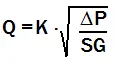
The relationship between Cv and Kv can be expressed as:
- Cv = 1.16 Kv (1)
- Kv = 0.862 Cv (2)
 |
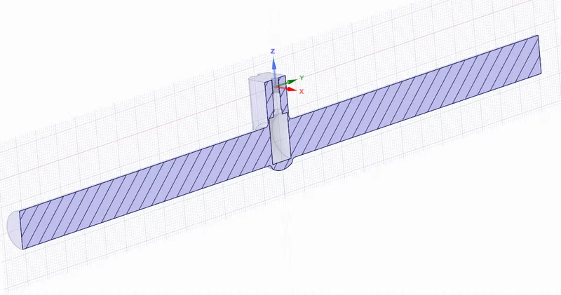 |
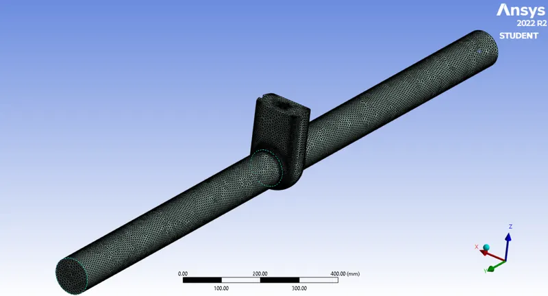
We perform meshing in the ANSYS MESHING using a mesh size of 7 mm and name the inlet and outlet.
 |
We use steady state, pressure based solver since we are interested in the end results and since the fluid is liquid which is incompressible and by enabling the gravity, we set the physics for the model. Here we have used the k-epsilon realizable model with enhanced wall functions. The fluid domian material is the water-liquid. Boundary conditions are pressure inlet of 10 Pa (gauge) and pressure outlet of 0 Pa. Hybrid initialization is used for this simulation and the mass flow rate is calculated for 150 iterations.
RESULTS
Mass flow rate (Q) is in metric units i.e, m3/h, pressure difference in Bar
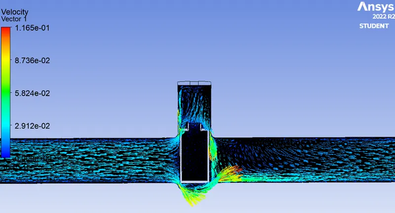
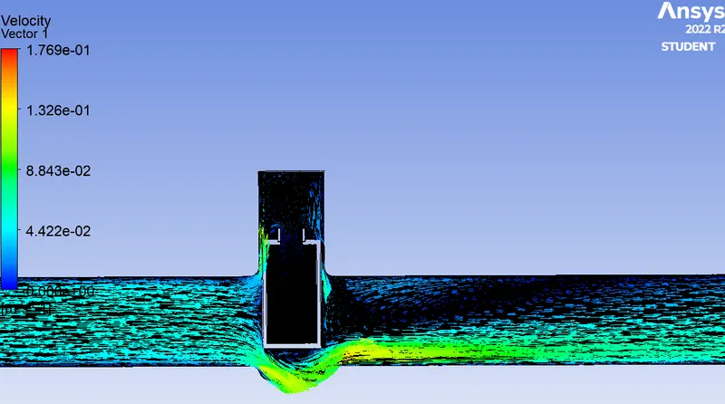
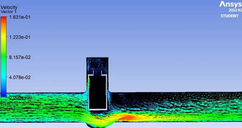
Velocity contour plots for various lifts
 |
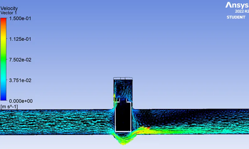 |
| Mass flow rate = -0.5 | Mass flow rate = -0.79 |
| Flow factor = 50 | Flow factor = 78.9 |
| Flow coefficient = 57.7 | Flow coefficient = 91.3 |
 |
|
| Mass flow rate = -1.18 | Mass flow rate = -1.36 |
| Flow factor = 117.9 | Flow factor = 139.9 |
| Flow coefficient = 136.4 | Flow coefficient = 157.2 |
 |
|
| Mass flow rate = -1.9 | Mass flow rate = -2.12 |
| Flow factor = 189.9 | Flow factor = 212 |
| Flow coefficient = 219.6 | Flow coefficient = 245 |
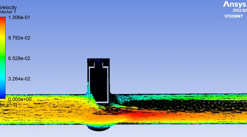 |
|
| Mass flow rate = -2.45 | Mass flow rate = -2.66 |
| Flow factor = 245.9 | Flow factor = 266.9 |
| Flow coefficient = 283.2 | Flow coefficient = 307.5 |
CONCLUSION
On lifting the gate gradually by 10 mm, the mass flow rate increases gradually as expected and so does the velocity, flow factor and the flow coefficient.