Project 1 : CFD Meshing for Tesla Cyber Truck
AIM: To check and solve all geometrical errors and assign appropriate PIDs for the given Cyber Truck model, perform surface meshing with target lengths of 4,3 and 2mm for various components i.e., Body,Tyres and Lights respectively and also apply element quality criteria, also perform surface meshing for various surfaces of wind tunnel and eliminate all the off elements.
PROCEDURE:
- Import the given CAD model onto the ANSA software. Check for geometrical errors.
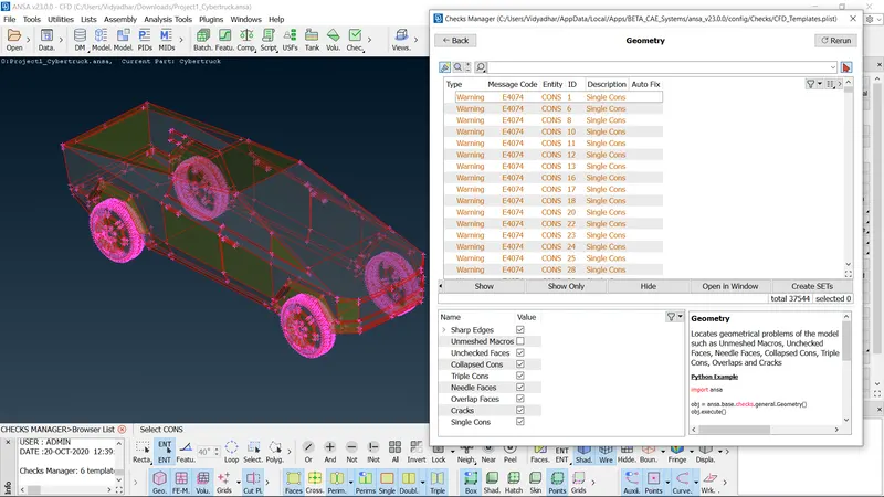
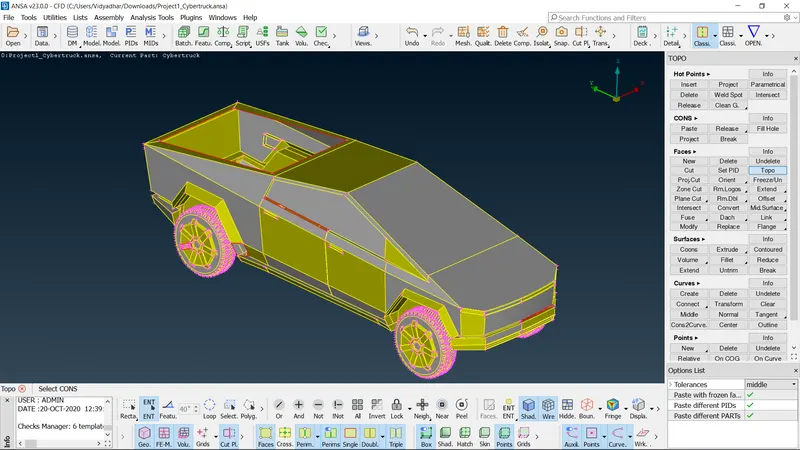
- Hit topo command so as to convert single cons to double cons automatically.
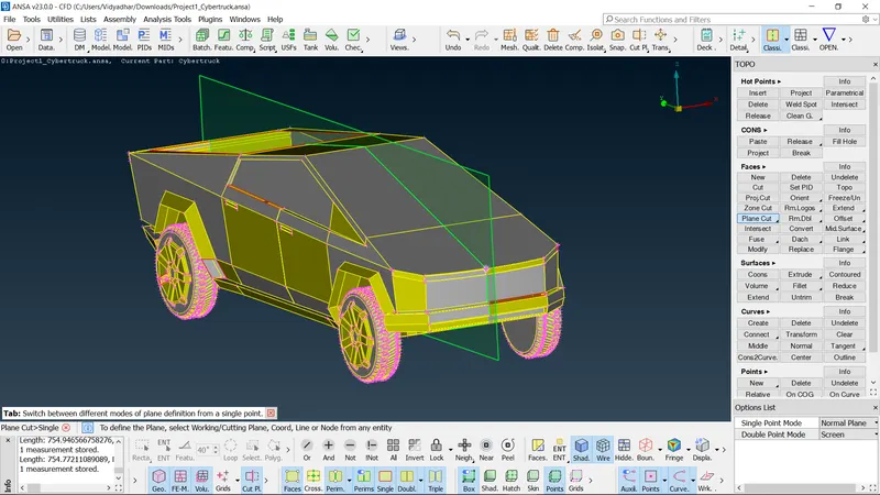
- Using plane cut command cut the model into two halves i.e., by selecting any 3 points.
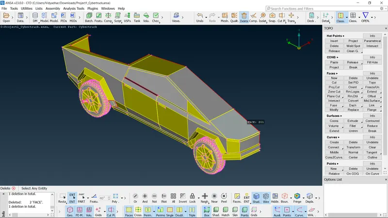
- Delete the half portion of the model.
- Then eliminate all the geometrical errors by carefully inspecting each and every geometry as depicted in the below snapshot.
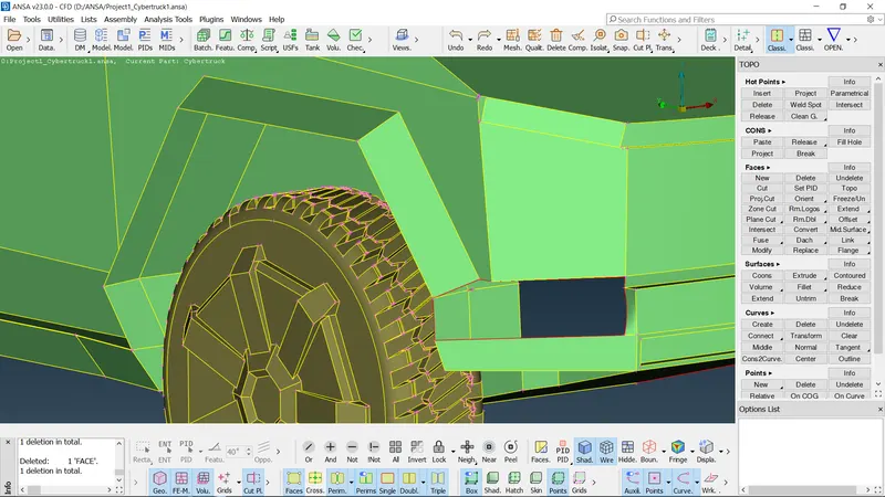
- Eliminate all the intersection errors.
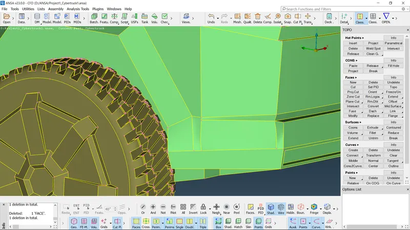
- After eliminating all the errors, validate the same by hitting geometry clean-up command. I
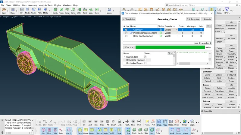
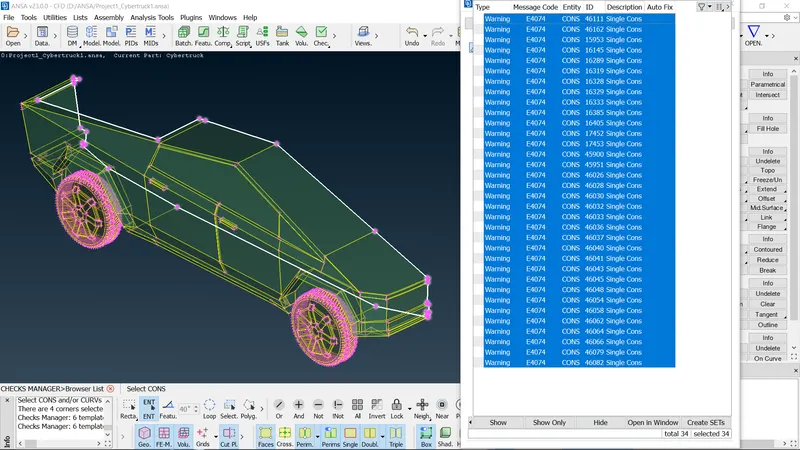
- Ignore all the single cons error as this error gets automatically resolved once the symmetrical operation is performed.
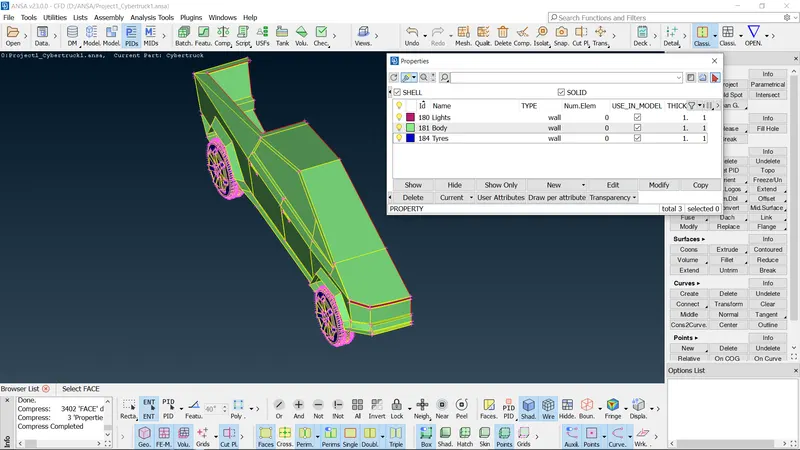
- Using compress command, delete all the PIDs that are not been assigned to the geometries and then assign appropriate PIDs to the various components.
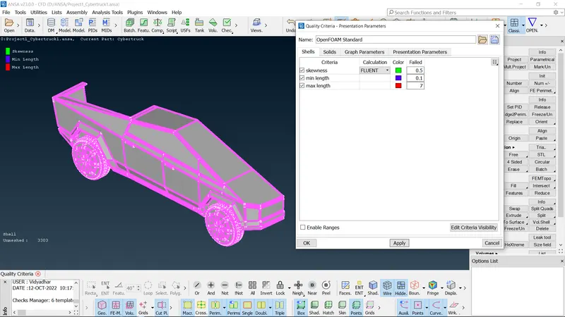
- Now switch to the mesh module. In the this module, set the Quality criteria parameters such as skewness, min length and max length to 0.5,0.1 and 7 mm respectively.
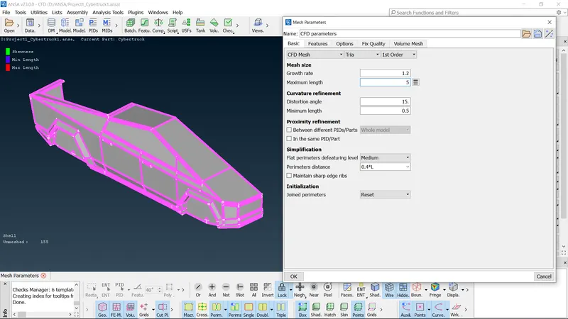
- Isolate the component we want to mesh i.e., Body and go to Mesh Parameters command and assign a target length of 4 mm by properly selecting the max length and min length. Repeat this procedure for the other components as well.
- Now select the perimeters and macros of the component we would like to mesh.
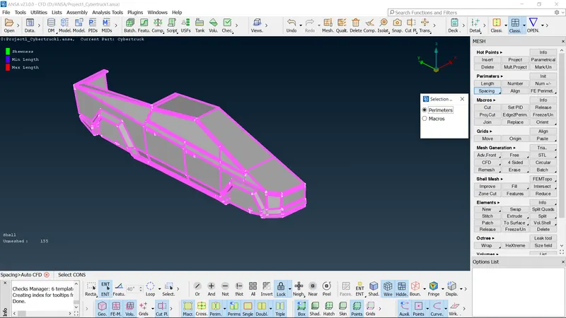
- Click OK after the selection is completed.
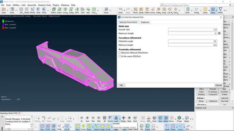
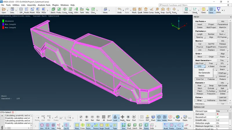
- Now make the mesh generated visible by hitting Mesh generation CFD command.
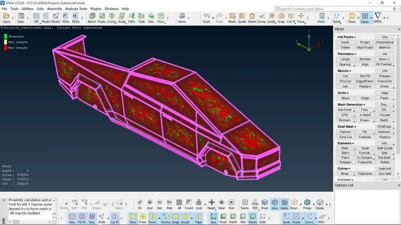
- Now as the below snapshot depicts the number of off elements, we need to eliminate these elements to clear the quality criteria.
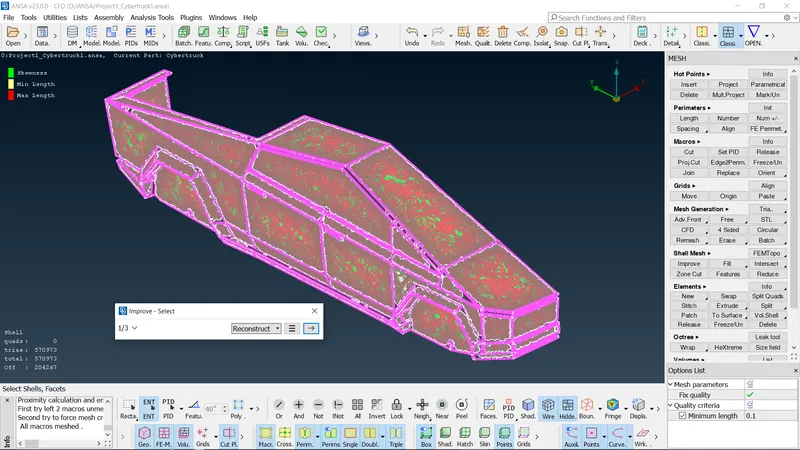
- Using improve reconstruct or reshape command, we can eliminate the off elements to certain extent. After that we need to eliminate the elements manually.
- Using move grids command, we can move the grid elements so as to achieve zero off elements.
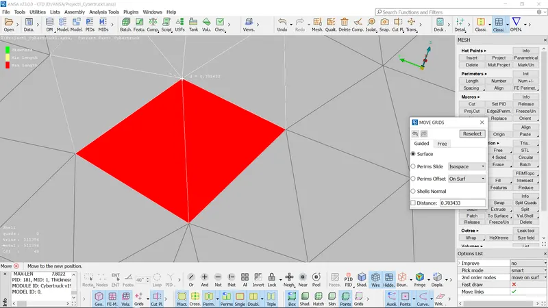
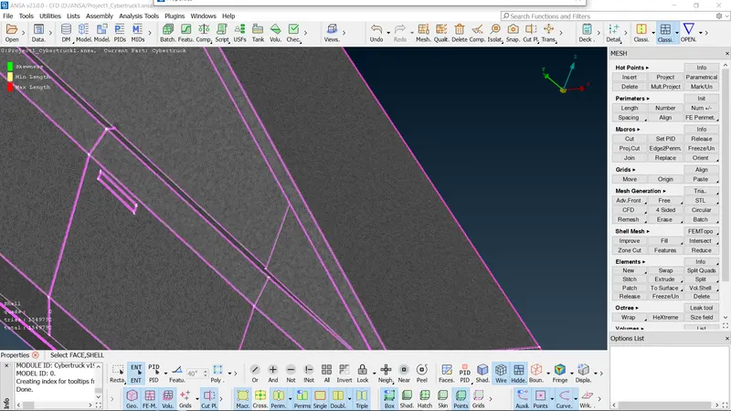
- Repeat the above procedure for all other components.
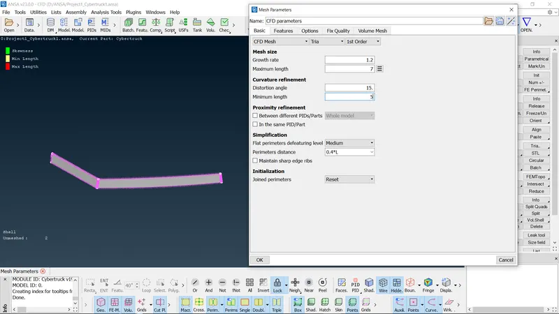
- Freeze the mesh generated by isolating the components individually as this would completely freeze the elements.
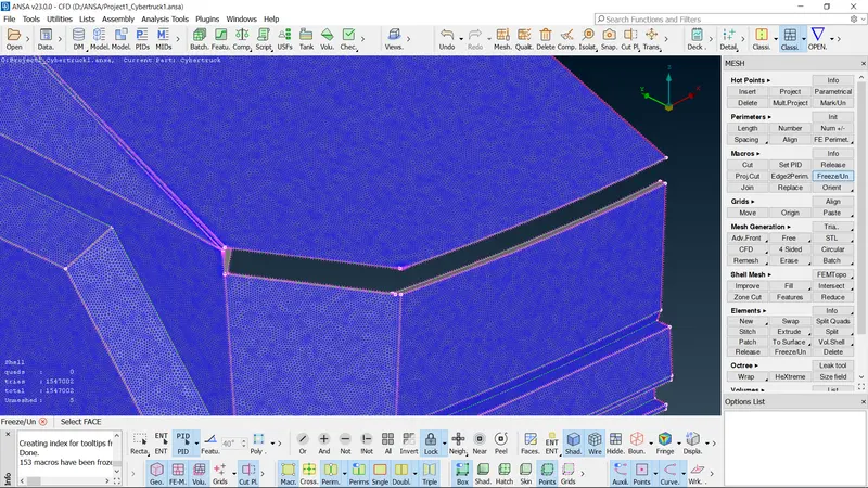
- Check if all the surfaces of the isolated component are meshed. For the surfaces which did not capture the mesh, go for free mesh generation as shown below and then freeze the same.
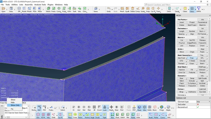

- Eliminate the off elements as discussed above.
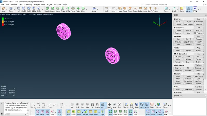
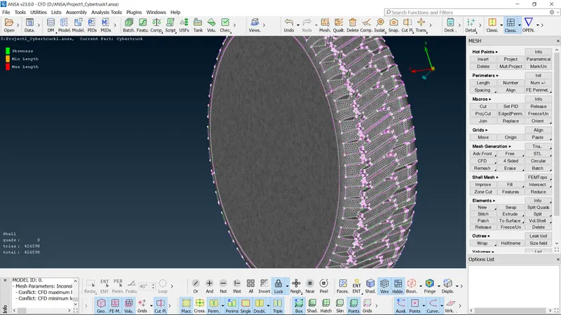
- Now unfreeze the mesh so as to perform futher operations.
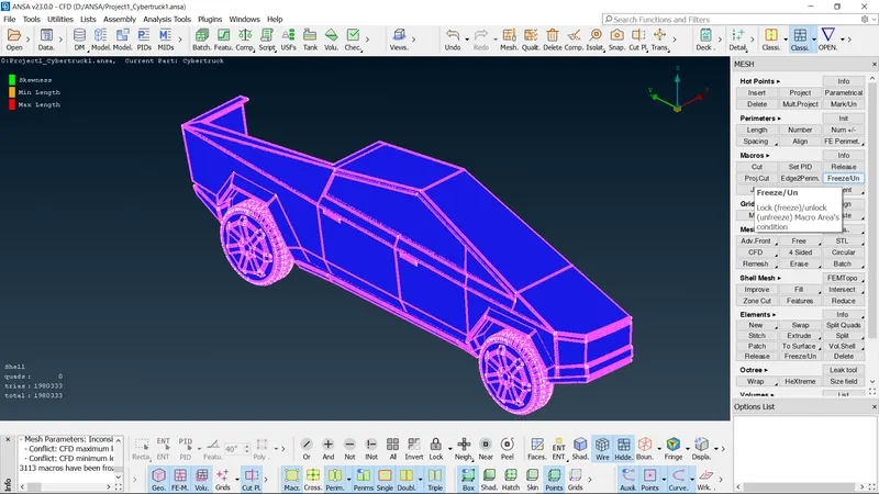
- Now perform symmetry operation using Transform copy command.
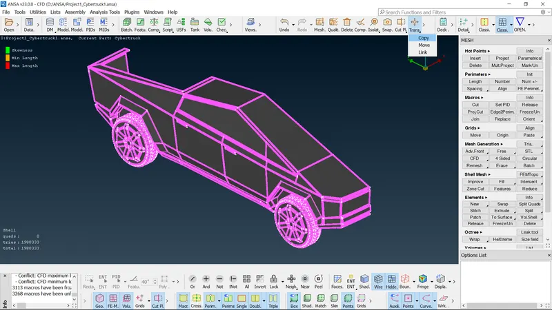
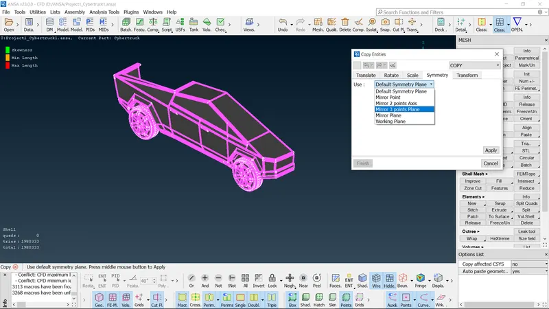
- In the copy entities command, select any 3 points about which we would like to perform symmetrical operation.
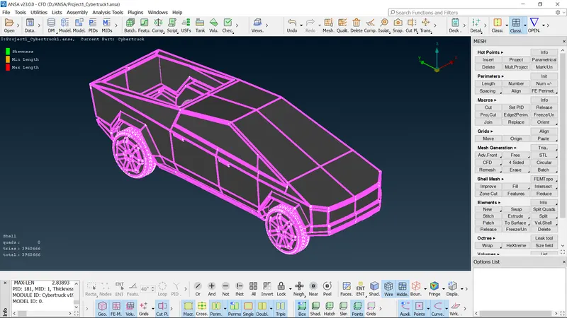
- Check for any unmeshed surfaces.
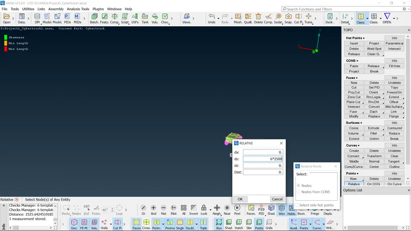
- Now in the topo module, generate points for creating wind tunnel surfaces as shown below. Use relative points command to create points at appropriate distances.
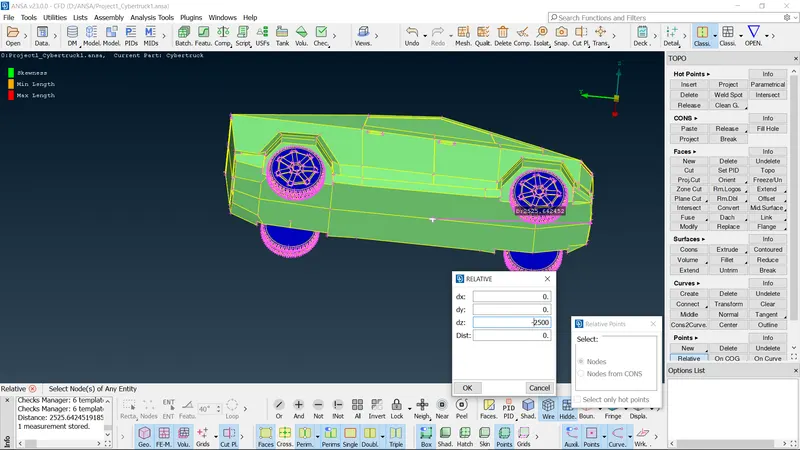
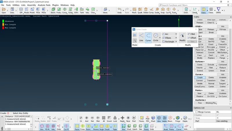
- Join these points using curves command.
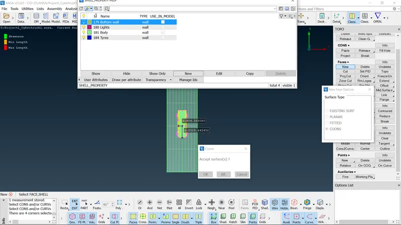
- Create the bottom wall surface of the wind tunnel and assign the PID for the same as shown below.
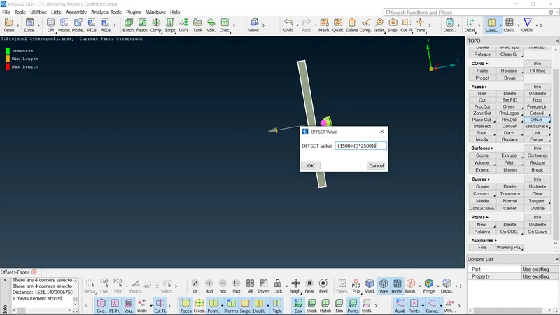
- Using offset command, create top wall surface at appropriate distance. Create side walls using new cons command.
- Isolate the bottom wall surface and assign it a mesh of appropriate target length as shown below. Repeat the same for top wall surface as well.
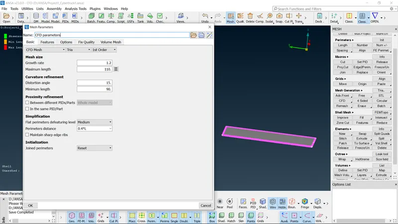
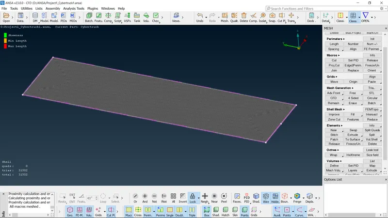
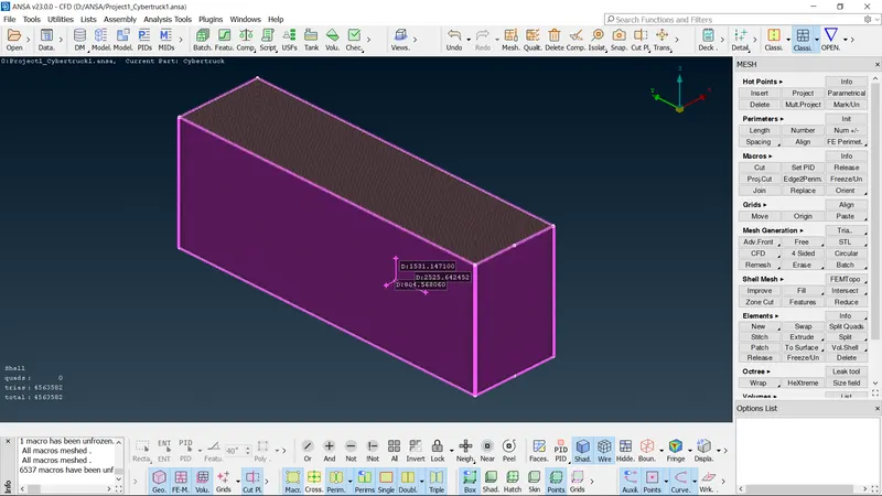
- For the side walls, manually create the mesh as it varies due to different target lengths assigned to top and bottom surfaces. Use a growth rate factor of 1.2 and mesh the side walls as well.
LEARNING OUTCOMES:
- Solving all the geometrical errors on half portion of the given model and Assign appropriate PIDs for the various components of the model.
- Understanding the difference between Mesh parameters and Quality criteria command.
- Generating mesh on the other half portion of the model by performing symmetrical operation.
- Understanding freeze/unfreeze command and applying the same to various components.
- Eliminating off elements using various tools such as reconstructing, reshaping the geometry using improve command, move the grids so as to eliminate the off elements using move command.
- Understanding the difference between paste command and create new suface command.
- Creating node points at appropriate distances from the model and joining these points using curves command and thus creating wind tunnel surfaces at appropriate distances from the given model.
- Generating mesh for these wind tunnel surfaces according to their specified mesh lengths.
- Understanding the growth rate factor and using the same so as to create mesh of varying target length.
RESULTS: All the geometrical errors were resolved and appropriate PIDs for the given Cyber Truck model were assigned, surface meshing with target lengths of 4,3 and 2mm for Body,Tyres and Lights respectively was performed. Also surface meshing for various surfaces of wind tunnel was performed and all the off elements were eliminated successfully.