Week 9 - Parametric study on Gate valve.
-
CHALLENGE FOR GATE VALVE SIMULATION:
Aim - For this challenge, you will have to perform a parametric study on the gate valve simulation by setting the opening from 10 % to 80%.
- Obtain the mass flow rates at the outlet for each design point.
- Calculate the flow coefficient and flow factor for each opening and plot the graph.
- Discuss the results of the mass flow rate and flow coefficient.
- Objective - To perform a parametric study on the gate valve simulation by setting the opening from 10 % to 80%.
- Simulate the flow of fluid through a gate valve.
- Calculate the mass flow rate corresponding to all design points.
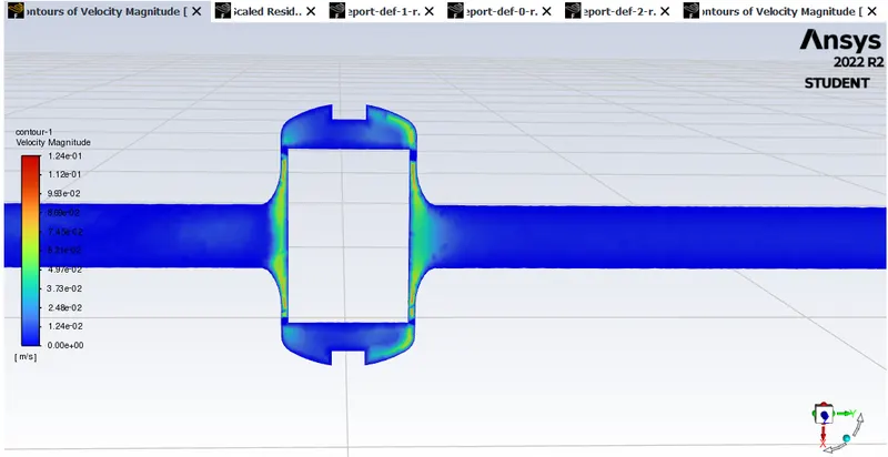
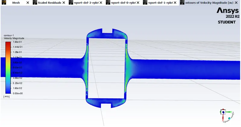
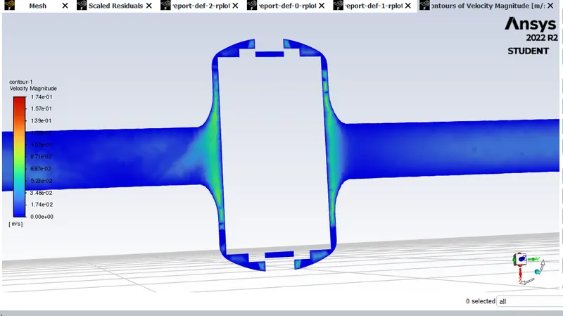
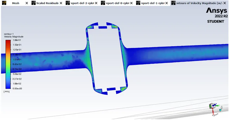
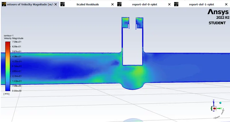
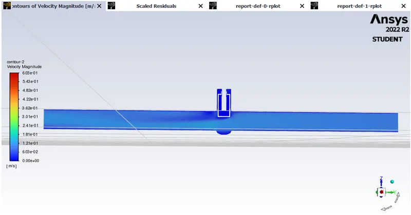
- Displays velocity contours and animations corresponding to all configuration points.
- Introduction
- Gate valves are often used to block fluid flow rather than to regulate the flow done by the gate valve.
- When fully open, a typical gate valve has an unobstructed flow path and therefore little flow resistance.
- Gate valves are primarily used on large diameter pipes (from 2 inches to the largest pipelines) as they are less complex than other types of large valves.
- The bonnet provides a leak-proof seal to the valve body.
- All-metal gate valves are used in ultra-high vacuum chambers to separate areas of the chamber.
- Gate valves can be mainly divided into two types: parallel type and wedge type.
- A parallel gate uses a flat gate between two parallel sheets and a common type is a knife gate designed with a sharp edge on the underside of the gate. The gate valve is the most common fitting for water systems.
- Parametric Studies
During component design, you can determine the impact of changing certain parameters such as dimensional parameters determine in the structure. - Plametric studies allow you to specify parameters for evaluation, define parameter ranges, specify design constraints, and analyze the consequences of variation for each parameter.
Parametric study requires: - Design target set to parametric dimensions.
- Parameters are specified for use in the simulation.
- Parameter range identified.
- Design criteria are specified.
- Various configurations are generated. After successfully generating the configuration, the simulation can be evaluated. You can further tune the parameters or design constraints until you get the desired result.
-
Mass flow rate:- It is defined as the mass of a substance flowing per unit time and it is given by the formula,
m = rho * Q
where m - mass flow rate ( kg/s )
rho - density of the fluid ( kg/m3 )
Q - flow rate ( m3/s
- Flow Coefficient:-The Flow Coefficient of a device is a relative measure of its efficiency at allowing fluid flow.
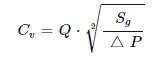
Where, Kv - flow factor
Q - volume flow rate ( m3/hr )
SG - specific gravity of the fluid ( for water = 1 )
ΔP - pressure drop ( bar )
-
Flow factor:- The flow factor is the flow coefficient in metric units. It is defined as the flow rate in cubic meters per hour of water at a temperature of 16deg C with a pressure drop of 1 bar. It is given by the formula,
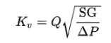
Where Kv - flow factor
Q - volume flow rate ( m3/hr )
SG - specific gravity of the fluid ( for water = 1 )
ΔP - pressure drop ( bar )
- Procedure
- Geometry
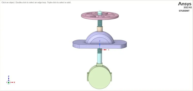
- Volume Extraction
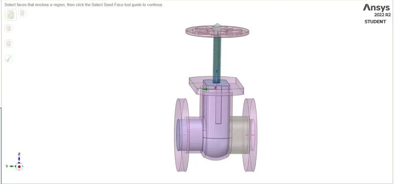
- Pull option is used
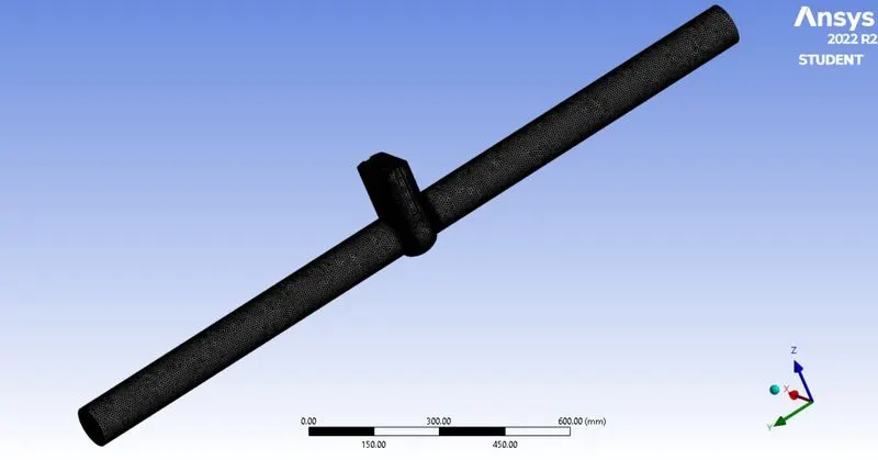
- Meshing
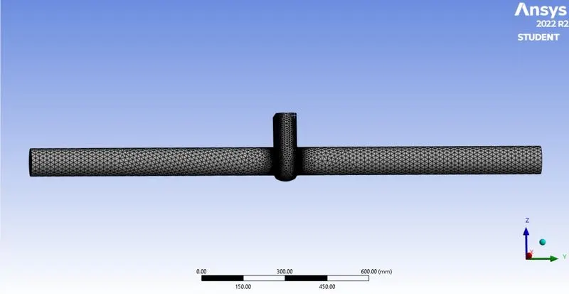
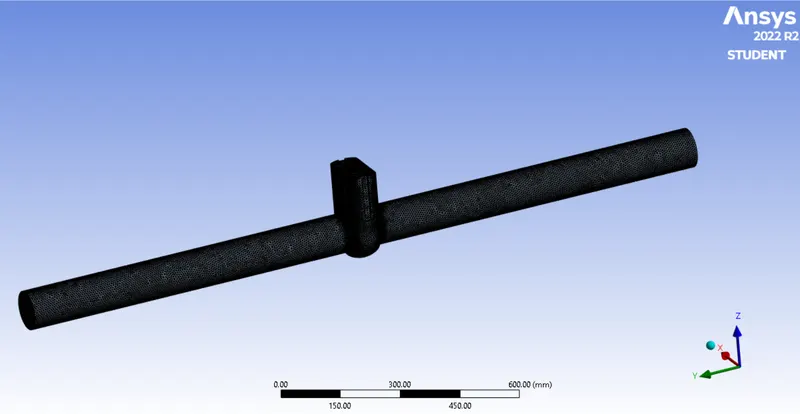
- Element size = 6mm
- Name selection
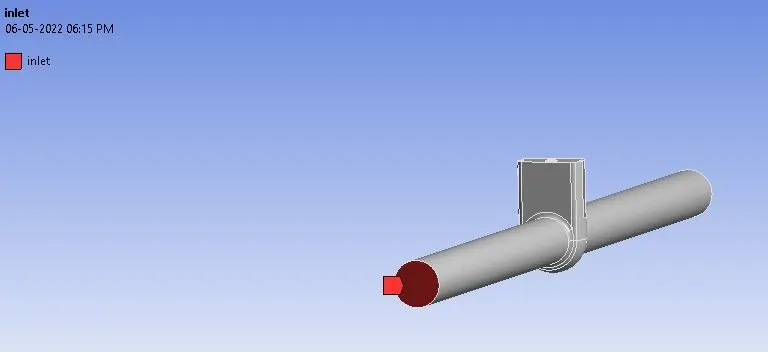
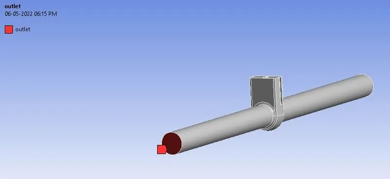
-
Setting Up Physics:
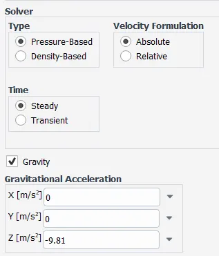
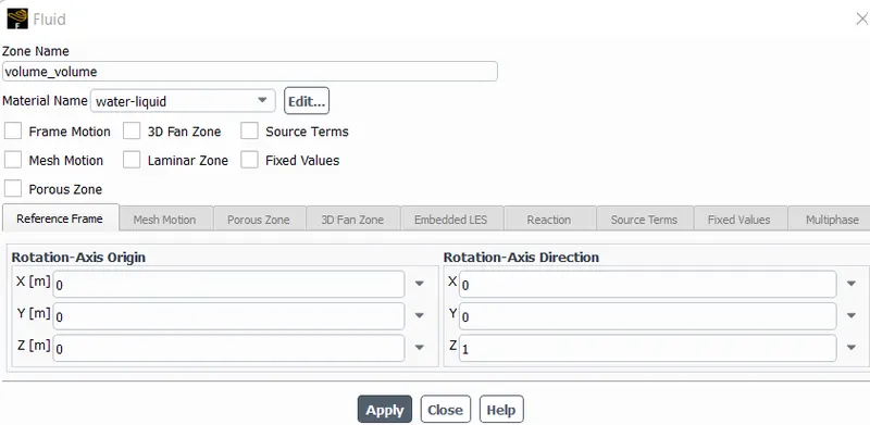
First of all the mesh is set up and the solver is defined as below:
Solver Type: Pressure Based Solver
Gravity: -9.81 (in negative z-direction)
Solver: Steady State
- Results
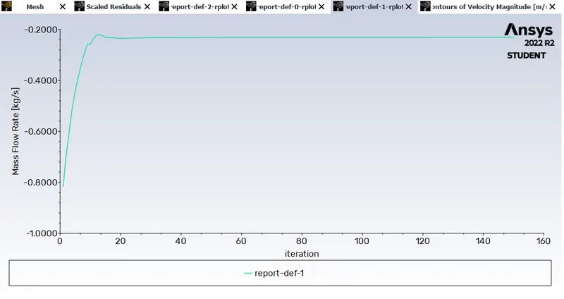
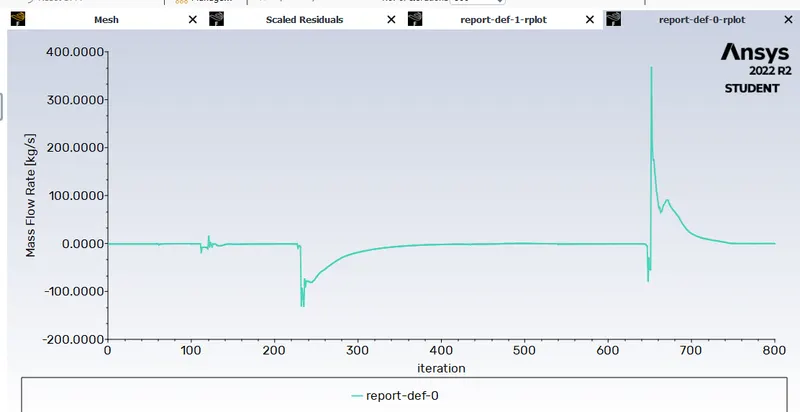
- The lift parameter is set and mass flow rate is included as the output parameter.
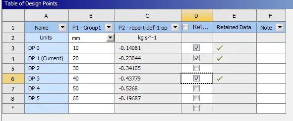
- DP 0) 10mm
- DP 1) 20mm
- DP 2) 30mm
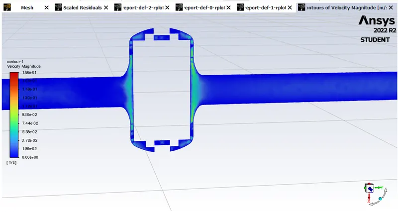
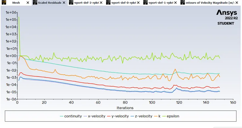
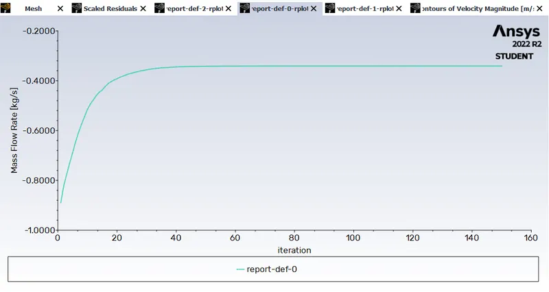
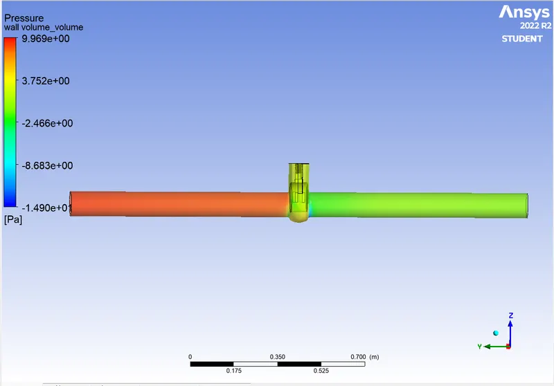
- DP 3) 40mm
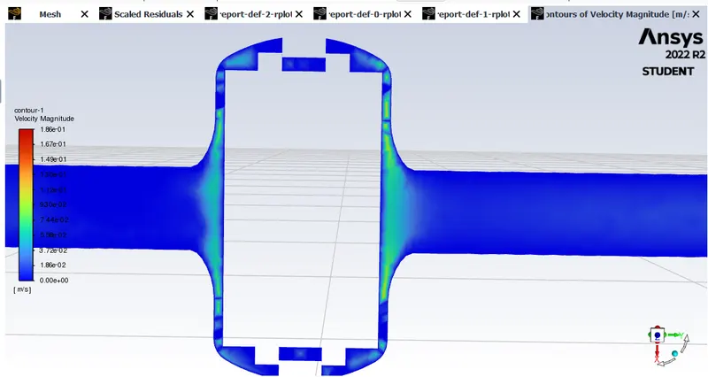
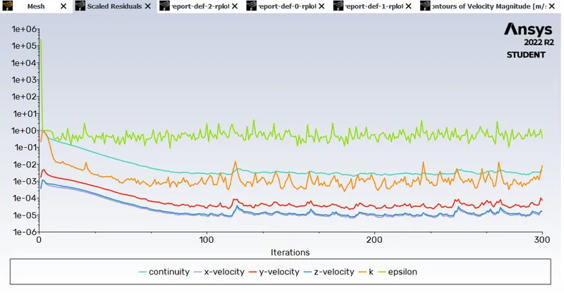
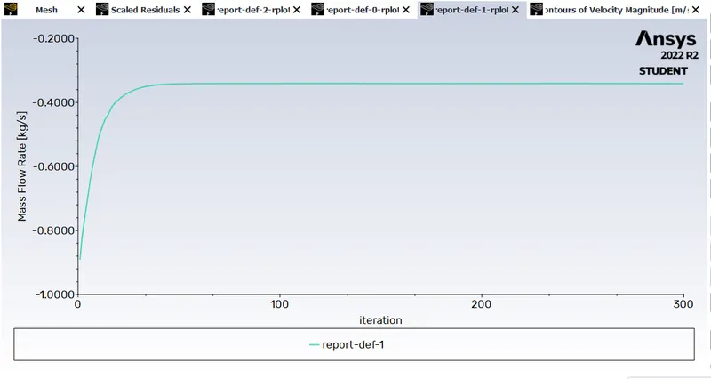
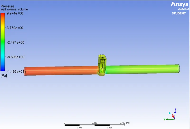
- DP 4) 50mm
- DP 5) 60mm
- DP 5) 70mm
- DP 5) 80mm
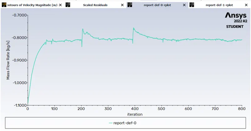
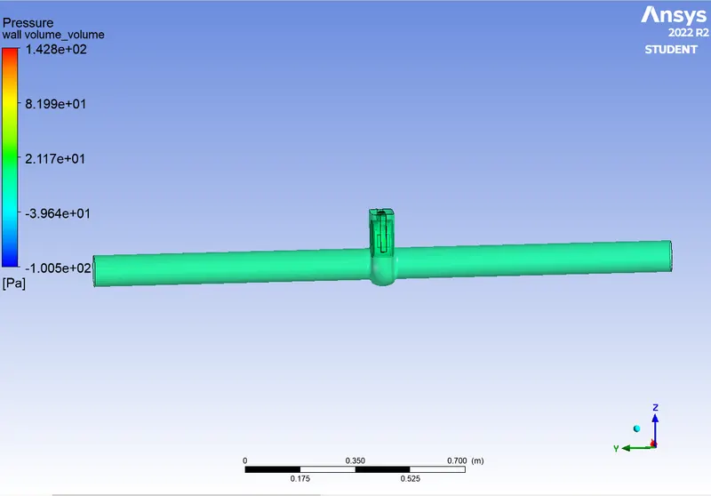
- Stepwise Explaination
- Here we run a simulation on the gate valve to see the effect of increasing the gate valve by various percentages from 10% to 80%. The Gate Disc Lift Parametric option allows you to parameterize the amount of lift to see different results and changes at different lift percentages.
- After looking at 10% of the buoyancy, let's parameterize the buoyancy and run the analysis.
- Then sequentially review all resulting contours and changes in other variables (mass flow rate, flow coefficient, flow coefficient, etc.) SpaceClaim.
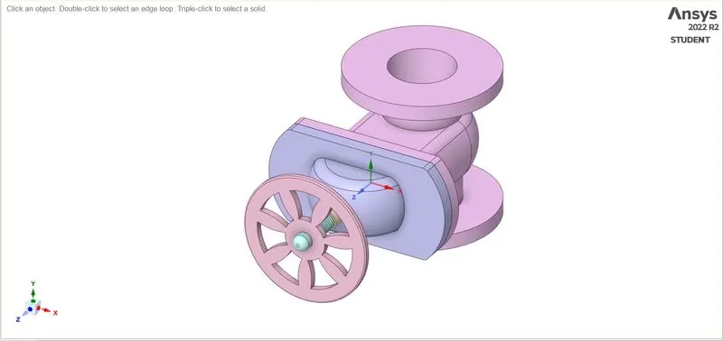
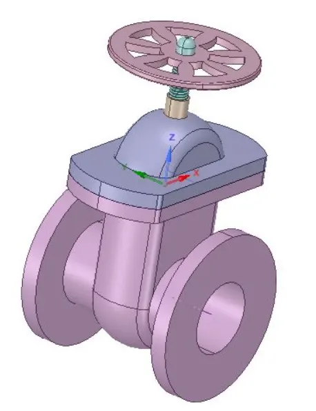
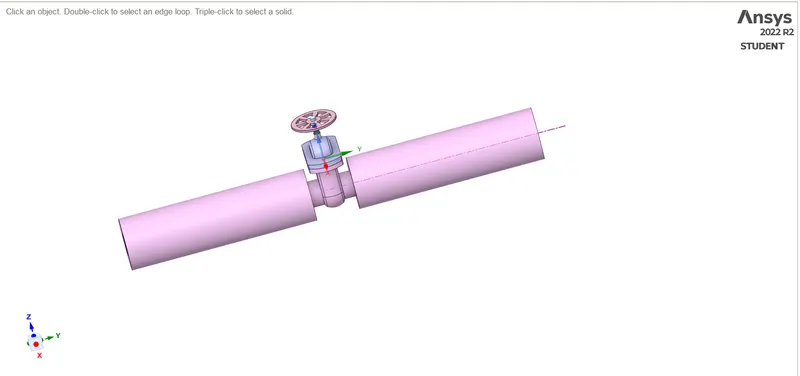
- Handwheel and spindle for raising and lowering the gate disc. The gate disc is attached to the bottom of the spindle. The
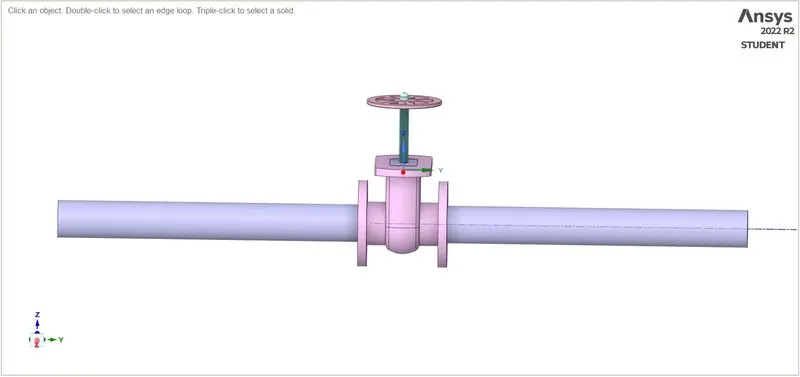
floor is the casing that covers the gate disc and the water flows through it. The two connections act as fluid inlet and outlet. - First, extend the geometry of the inlet and outlet openings by 800 mm each. It should look like the picture below.
- After expansion, select the inlet, outlet and top edge of the "bottom" part to create the liquid volume.
- After creating the liquid volume, hide and suppress all physics parts. Avoid covering gate discs and spindles where a large amount of fluid must be created to contain the required hard boundaries.
- Then use the Move option to raise the slider by 10 mm and click the P icon next to the dimension to parameterize the opening of the slider.
- Sets the solid volume within the liquid volume without hiding the bottom, gating disk and spindle for parameterization, updating for context.
- First, the mesh is set up and the solver is defined as follows:
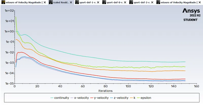
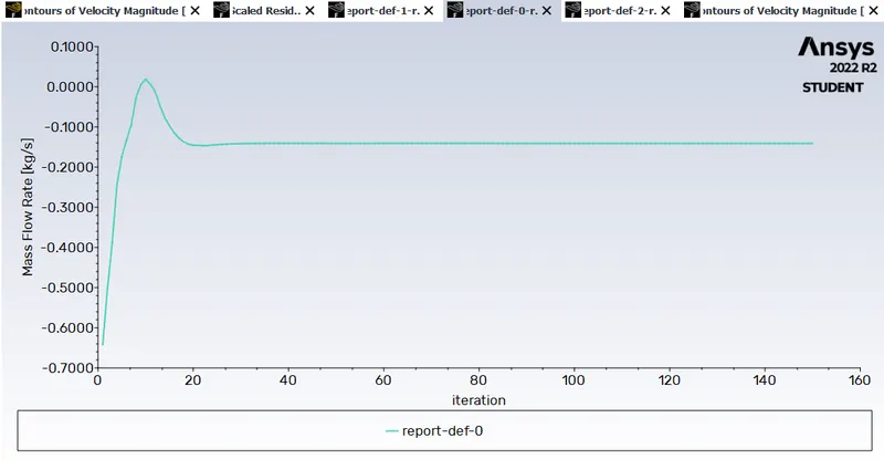
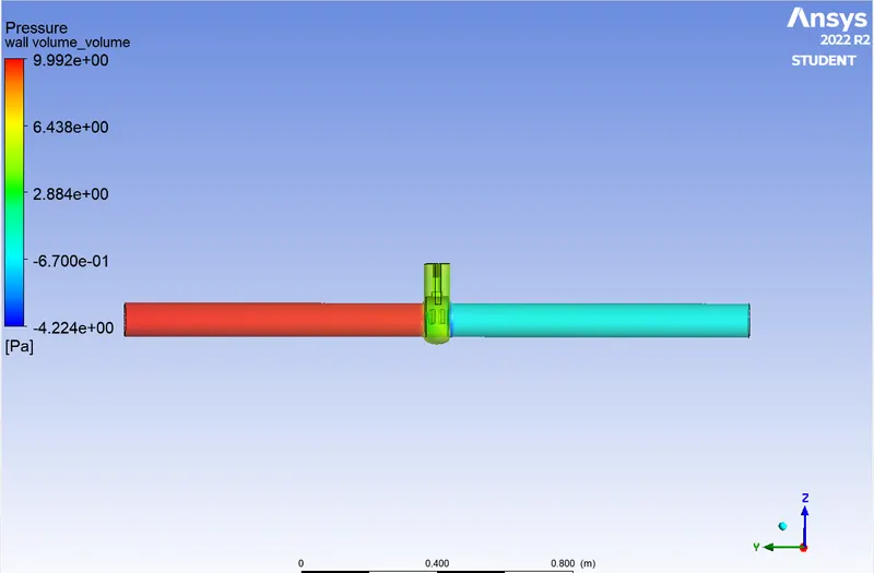
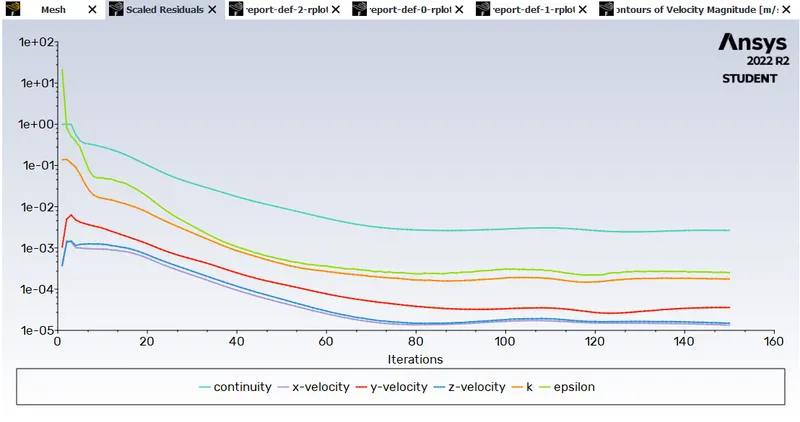
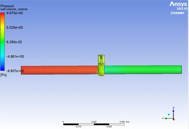
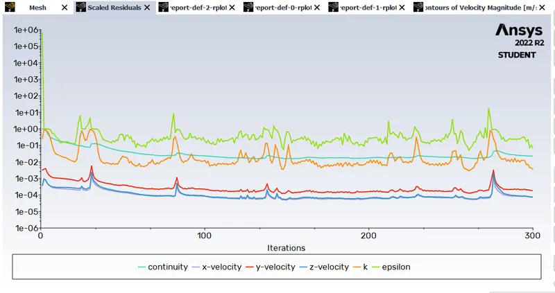
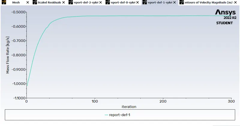
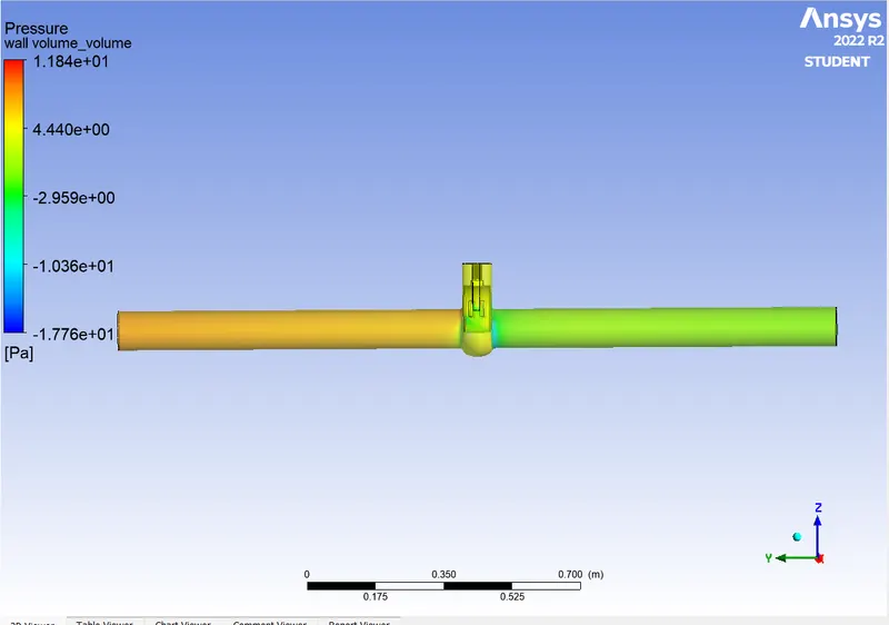
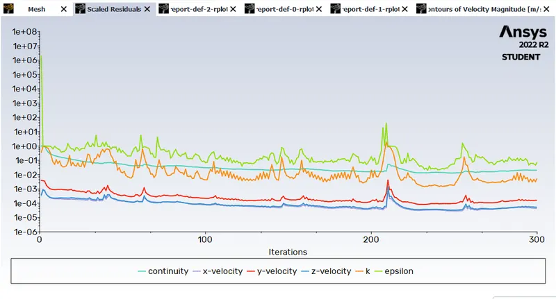
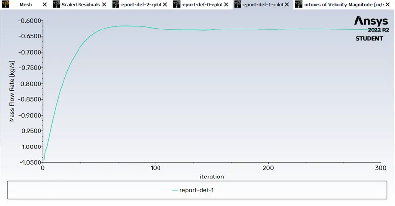
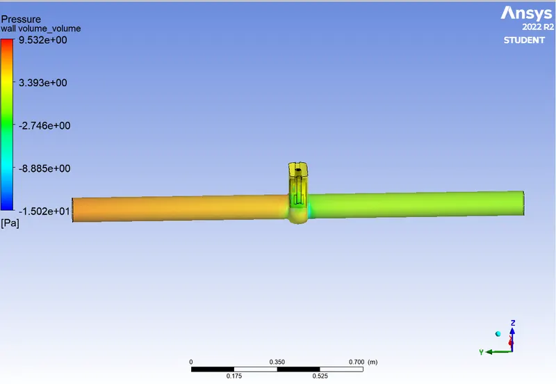
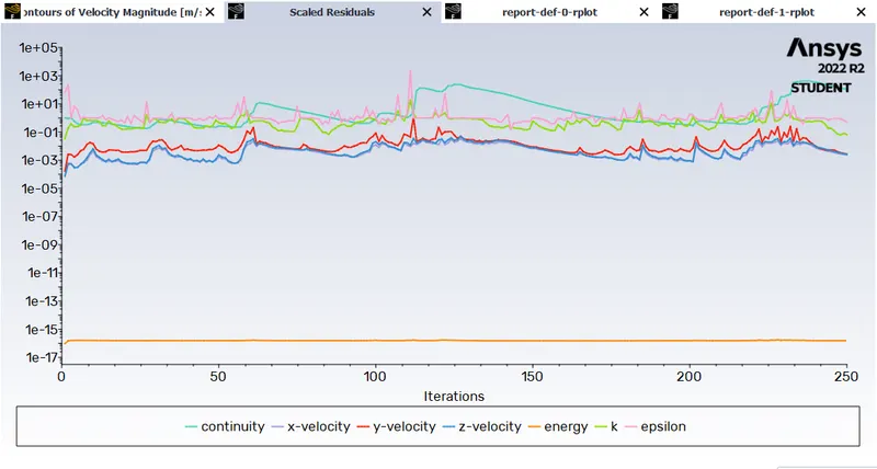
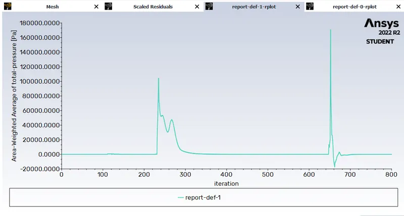
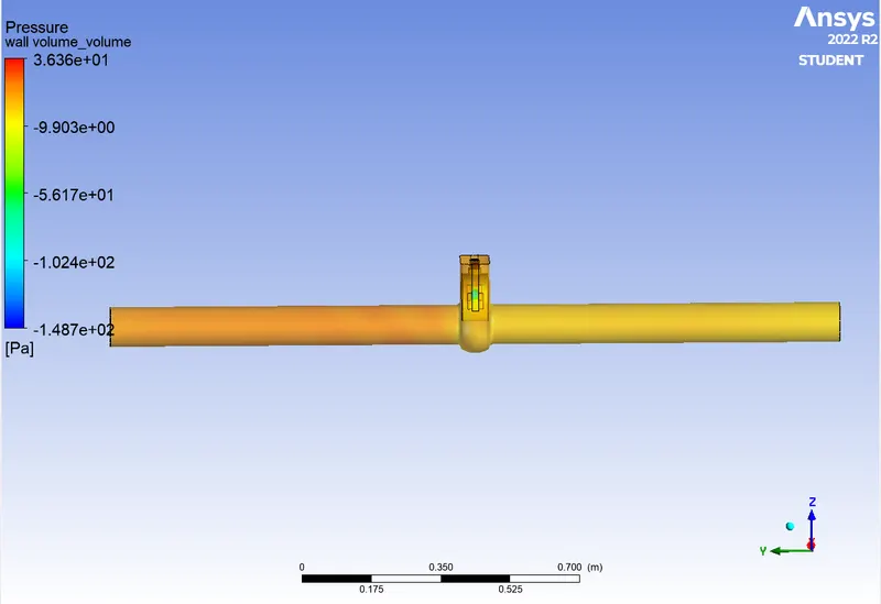
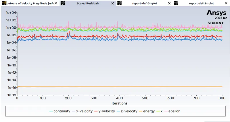
Output Boundary Condition: Pressure Output - The model is initialized with standard initialization and data from the inputs are computed. The solution converges. contours are plotted for mass flow rate and pressure .
- Parametric results
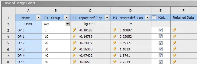

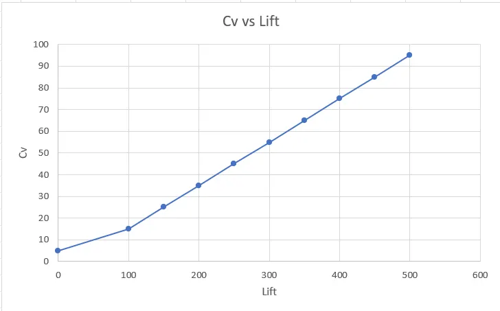
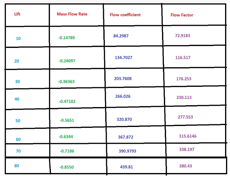
- From the table data and graph above, it can be seen that opening the gate valve or stroke of the gate valve increases the mass flow rate. As the mass flow rate increases, the flow coefficient increases.
- Increased flow coefficient is also seen at each design point from 10 to 80 mm stroke.
- Mass Flow, Flow Coefficient, and Flow Coefficient plots are therefore proportional to the opening of the gate valve.
- Conclusion
- As the opening percentage increases, the mass flow rate and velocity increases. This is because there are more paths for water to flow.
- Gate valve must operate in fully open or fully closed position. A partially open gate can cause vibration and damage the gate valve.
- Also, the gate valve should close gradually, not abruptly. This can cause a water hammer effect and damage the gate valve again.
- Flow coefficient and flow factor increase with increasing aperture ratio. As the opening percentage increases, the differential pressure across the gate valve decreases. This is because the flow is less blocked.
- The flow is proportional to the absolute inlet pressure.
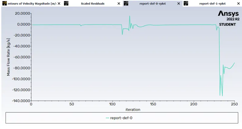
- The negative sign in the mass flow rate term comes due to mass leaving at the outlet.
- Parametric study helps a lot to reduce the solving time in studying the effect of change of parameters on the system
- As flow rate is increased, flow factor (Kv) increases as a result of which flow co-efficient (Cv) also increased.