Week 9 - Parametric study on Gate valve.
Aim: To conduct parametric study on gate valve>
Objective:
1. Simulate the flow of fluid through a gate valve.
2. Perform the paramatic study on the gate valve by setting design points corresponding to the positions of the lift of the spindle.
3. Calculate the mass flow rate corresponding to all the design points.
Geometry:
Valve Opening at 10%:
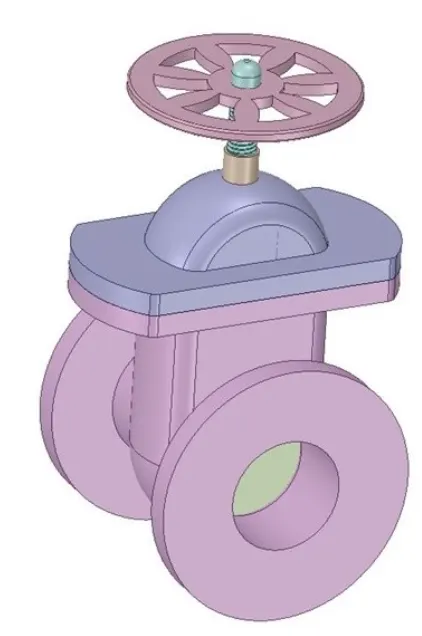
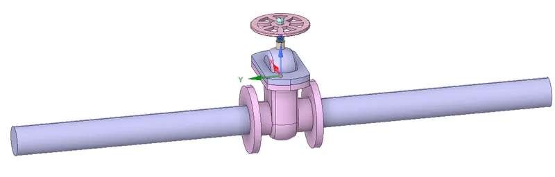
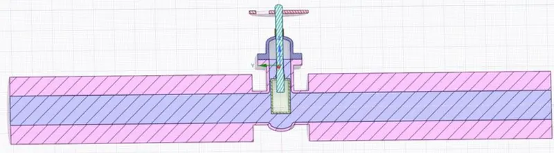
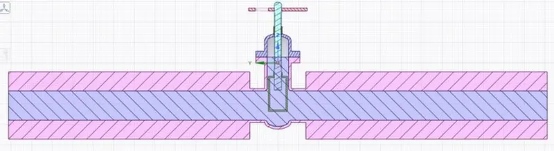
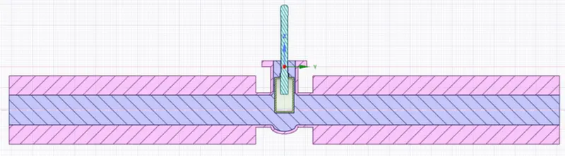
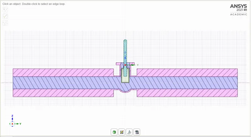
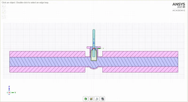
- The geometry is imported into SpaceClaim.
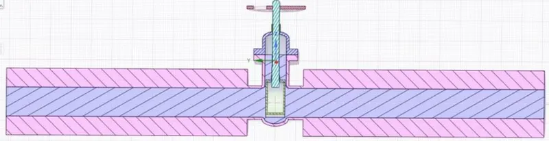
- Then the gate disc component is selected and given a lift of 10mm by using the move tool available in the Ansys SpaceClaim and the lift is parameterized.
- Then the inlet and outlet faces are pulled up to a distance of 800mm.
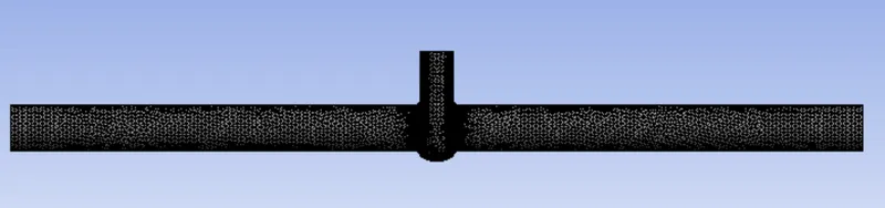
- Then the fluid volume is extracted from the model by using the volume extraction tool available in Ansys Spaceclaim.
- Then the solid components are suppressed for physics.
Meshing:
Setup:
1. Solver: Steady
2. Type: Pressure Based
3. Gravitational Acceleration:
- X: 0
- Y: 0
- Z: -9.81 m/s2
4. Turbulence Model: Realizable k- epsilon with Standard Wall Function
5.Cell Zone Condition:
- Fluid: Water
6. Material Specifications:
- Material: water-liquid (H2o)
- Density: 998.2 Kg/m3
- Viscosity: 0.001003 Kg/m-s
6. Boundaries:
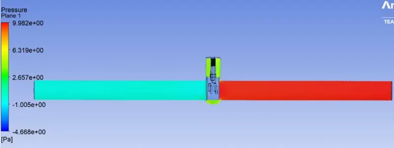
- Inlet: Pressure = 10 Pa(Gauge Pressure)
- Outlet: Pressure= 0 Pa (Gauge Presssure)
7. Solution Methods: Coupled
8. Initialization:
- Method: Standard Initialization from the Inlet
Results:
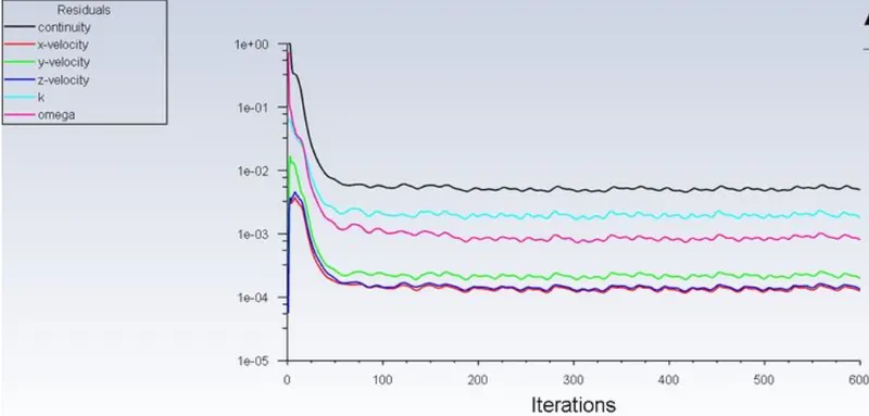
Case-1-Lift -10 mm
Residual:
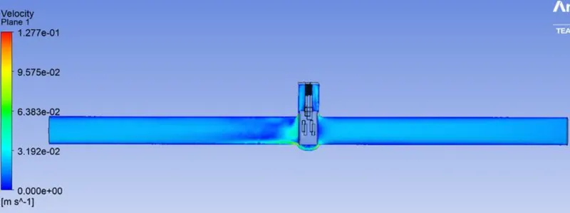
VELOCITY CONTOUR:
PRESSURE CONTOUR:
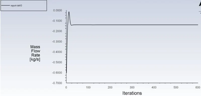
MASS FLOW RATE:
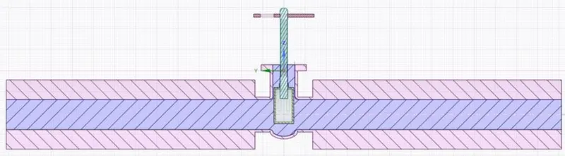
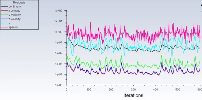
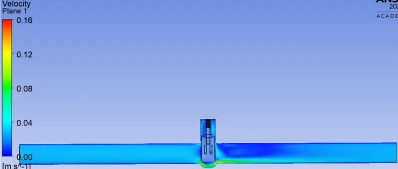
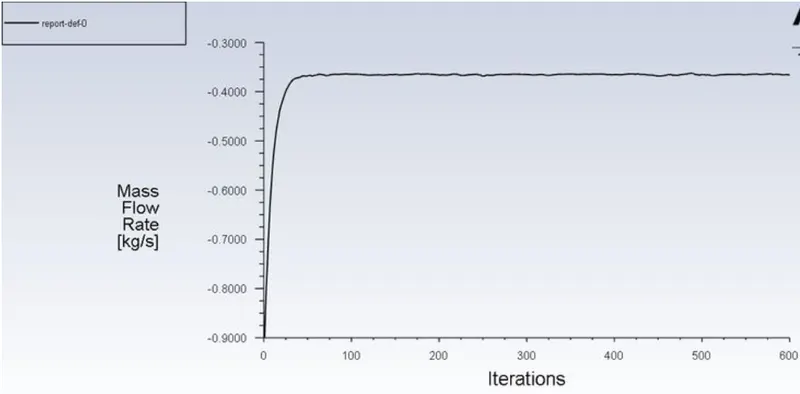
Case-2-Lift -20 mm
RESIDUAL:
VELOCITY CONTOUR:
MASS FLOW RATE:
CASE 3 – LIFT = 30MM
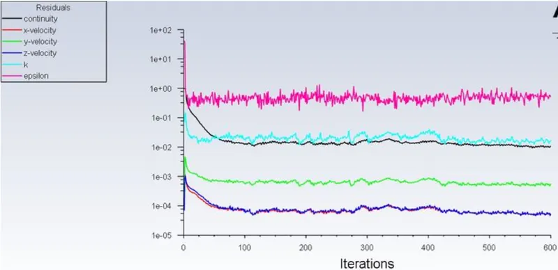
RESIDUAL:
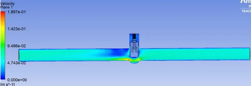
VELOCITY CONTOUR:
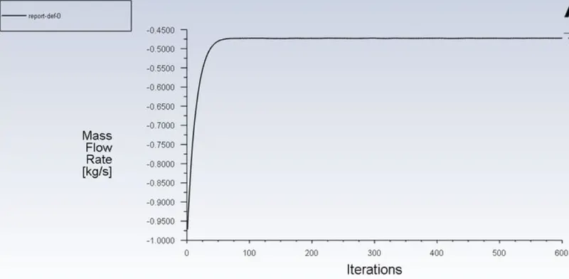
MASS FLOW RATE:
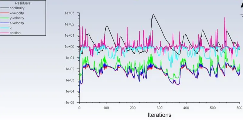
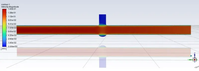
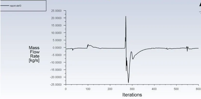
CASE 4 – LIFT = 40MM:
RESIDUAL:
VELOCITY CONTOUR:
MASS FLOW RATE:
CASE 5 – LIFT = 50MM:
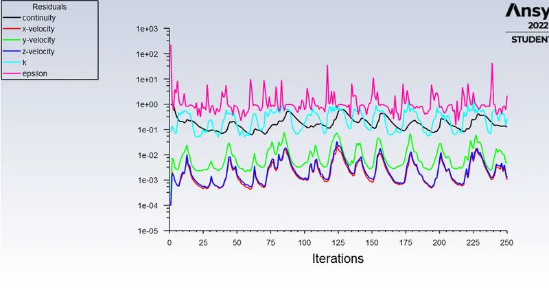
RESIDUAL:
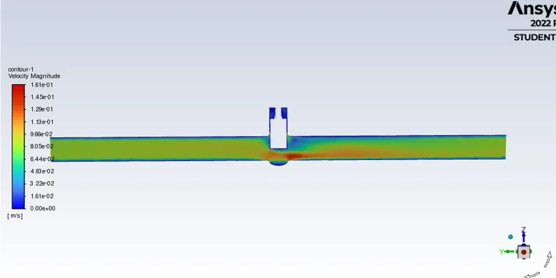
VELOCITY CONTOUR:
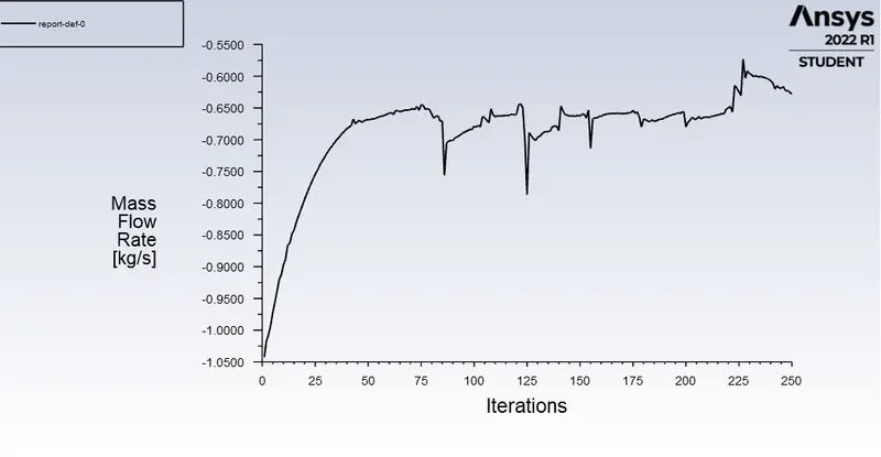
MASS FLOW RATE:
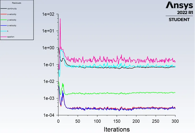
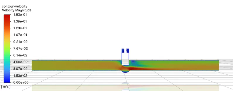
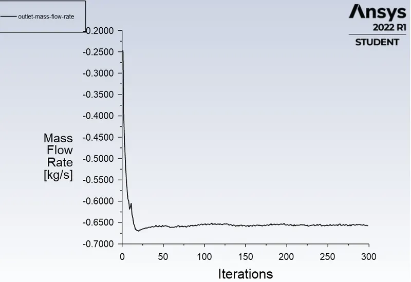
CASE 6 – LIFT = 60MM:
RESIDUAL:
VELOCITY CONTOUR:
MASS FLOW RATE:
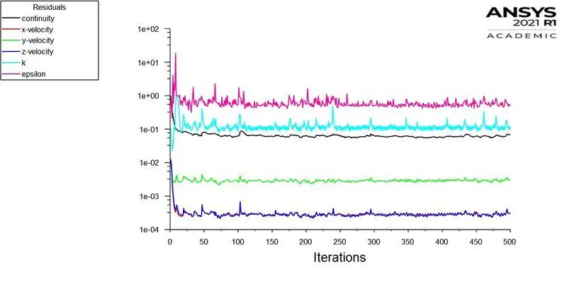
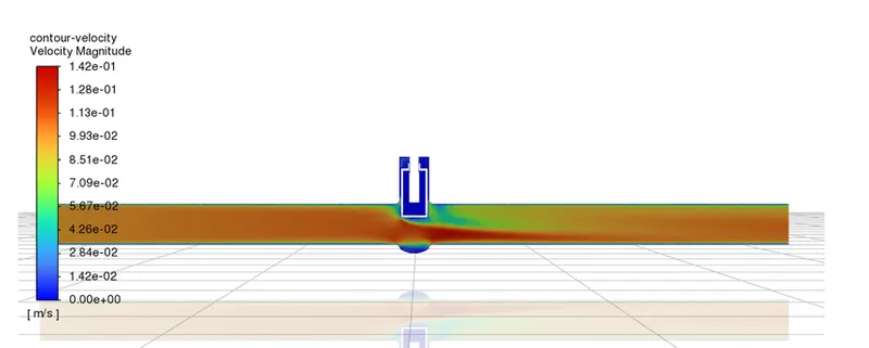
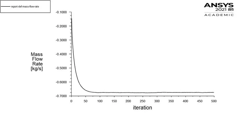
CASE 7 – LIFT = 70MM:
RESIDUAL:
VELOCITY CONTOUR:
MASS FLOW RATE:
CASE 8 – LIFT = 80MM:
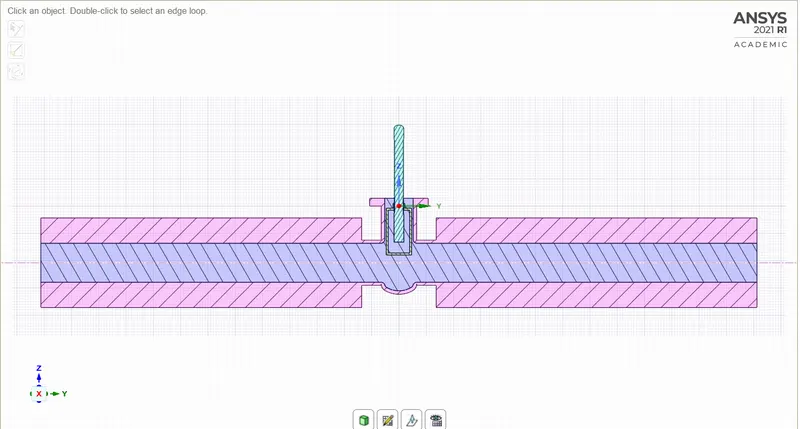
SECTIONAL VIEW:
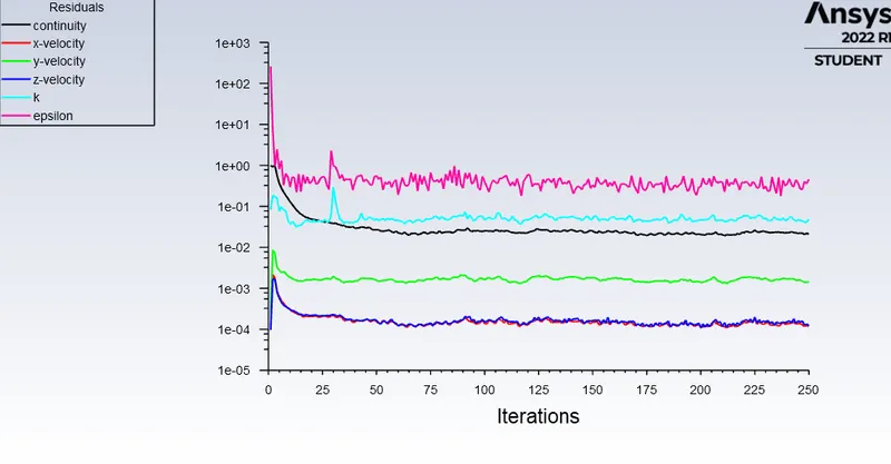
RESIDUAL:
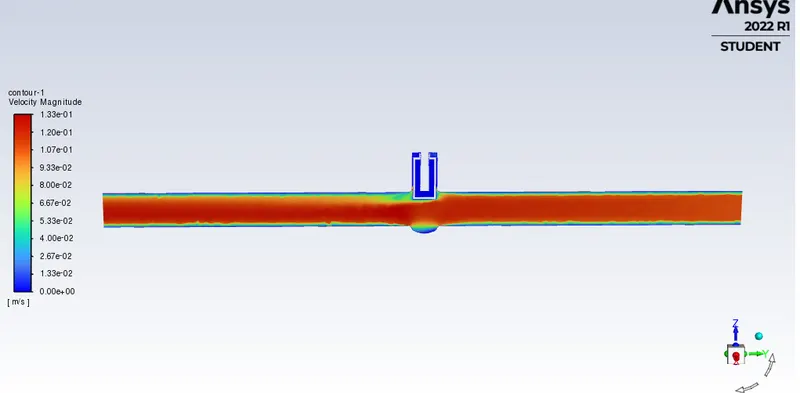
VELOCITY CONTOUR:
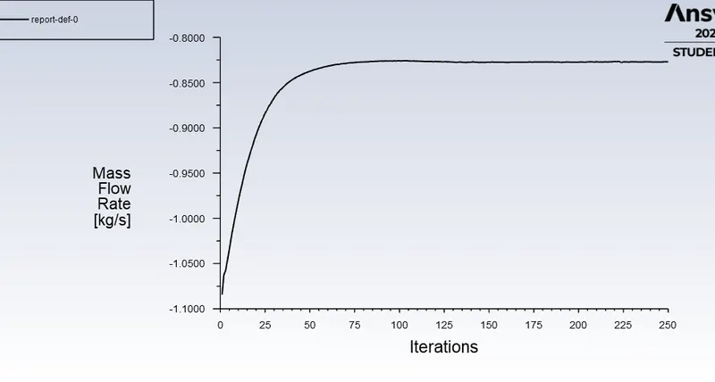
MASS FLOW RATE:
MASS FLOW RATE PARAMETRIC RESULTS:
Flow coefficient:
Pressure Drop = Total pressure at the inlet - Total pressure at the outlet.
Therefore, = 10 - 0 = 10 Pa
Cv=Q*(√SG)/ΔP
Conclusion:
| Disc Lift | Mass Flow Rate | Flow Coefficient | Flow Factor |
| 10 mm | 0.14976 | 84.2987 | 72.9183 |
| 20 mm | 0.23915 | 134.7027 | 116.5178 |
| 30 mm | 0.36216 | 203.7608 | 176.253 |
| 40 mm | 0.47264 | 266.0268 | 230.1131 |
| 50 mm | 0.56986 | 320.8708 | 277.5532 |
| 60 mm | 0.65795 | 367.8724 | 315.6146 |
| 70 mm | 0.69473 | 390.9793 | 338.197 |
| 80 mm | 0.78115 | 439.81 | 380.43 |
Conclusion:
1. Mass flow rate gradually increases as the lift of gate disc is increased.
2. The variation of flow coefficient and flow factor with the opening of the valve is studied by using parametric.
3. Parametric study is time reducing option when studying the effects of changes of certain parameters on a system.
4. Flow coefficient plays important role in the selection of valve and sizing of a valve, so calculating it is necessary.
5. flow coefficient also helps in computing the efficiency of the system and the effect of pressure on the system.