Week 9 - Parametric study on Gate valve.
AIM:
To perform a parametric study on the gate valve simulation by setting the valve lift from 10 to 80%.
OBJECTIVE:
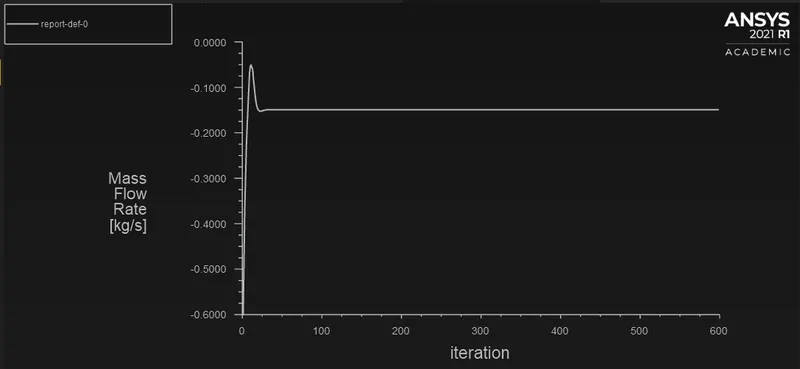
- To obtain the mass flow rates at the outlet for each design point.
- To calculate the flow coefficient and flow factor for each opening and plot the graph
- Discuss the results of the mass flow rate and flow coefficient.
INTRODUCTION:
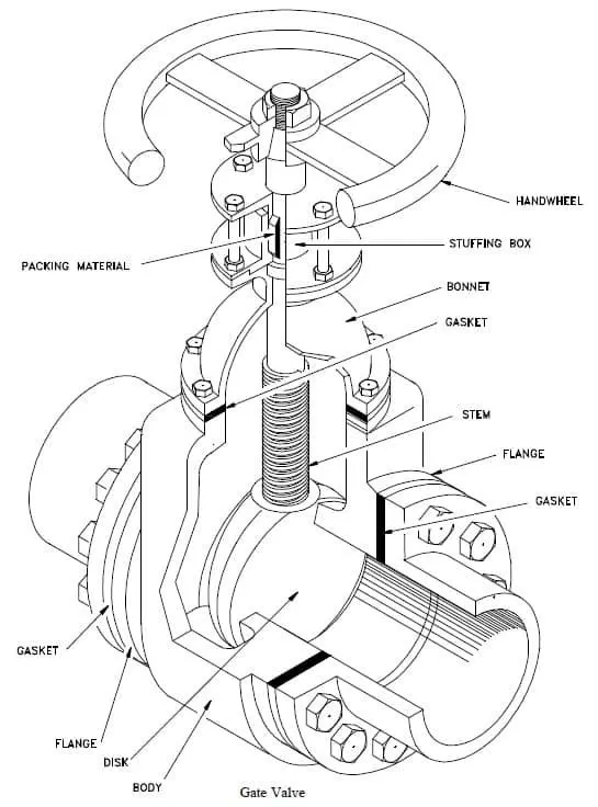
A gate valve, also known as a sluice valve, is a valve that opens by lifting a barrier (gate) out of the path of the fluid. Gate valves require very little space along the pipe axis and hardly restrict the flow of fluid when the gate is fully opened. The gate faces can be parallel but are most commonly wedge-shaped (in order to be able to apply pressure on the sealing surface).
TYPICAL USE:
Gate valves are used to shut off the flow of liquids rather than for flow regulation. When fully open, the typical gate valve has no obstruction in the flow path, resulting in very low flow resistance. The size of the open flow path generally varies in a nonlinear manner as the gate is moved. This means that the flow rate does not change evenly with stem travel. Depending on the construction, a partially open gate can vibrate from the fluid flow.
Gate valves are mostly used with larger pipe diameters (from 2" to the largest pipelines) since they are less complex to construct than other types of valves in large sizes.
At high pressures, friction can become a problem. As the gate is pushed against its guiding rail by the pressure of the medium, it becomes harder to operate the valve. Large gate valves are sometimes fitted with a bypass controlled by a smaller valve to be able to reduce the pressure before operating the gate valve itself.
Gate valves without an extra sealing ring on the gate or the seat are used in applications where minor leaking of the valve is not an issue, such as heating circuits or sewer pipes.
VALVE CONSTRUCTION:
Common gate valves are actuated by a threaded stem that connects the actuator (e.g. handwheel or motor) to the gate. They are characterised as having either a rising or a nonrising stem, depending on which end of the stem is threaded. Rising stems are fixed to the gate and rise and lower together as the valve is operated, providing a visual indication of valve position. The actuator is attached to a nut that is rotated around the threaded stem to move it. Nonrising stem valves are fixed to, and rotate with, the actuator, and are threaded into the gate. They may have a pointer threaded onto the stem to indicate valve position, since the gate's motion is concealed inside the valve. Nonrising stems are used where vertical space is limited.
Gate valves may have flanged ends drilled according to pipeline-compatible flange dimensional standards.
Gate valves are typically constructed from cast iron, cast carbon steel, ductile iron, gunmetal, stainless steel, alloy steels, and forged steels.
All-metal gate valves are used in ultra-high vacuum chambers to isolate regions of the chamber.
Bonnet:
Bonnets provide leakproof closure for the valve body. Gate valves may have a screw-in, union, or bolted bonnet. A screw-in bonnet is the simplest, offering a durable, pressure-tight seal. A union bonnet is suitable for applications requiring frequent inspection and cleaning. It also gives the body added strength. A bolted bonnet is used for larger valves and higher pressure applications.
Pressure seal bonnet:
Another type of bonnet construction in a gate valve is pressure seal bonnet. This construction is adopted for valves for high pressure service, typically in excess of 2250 psi (15 MPa). The unique feature of the pressure seal bonnet is that the bonnet ends in a downward-facing cup that fits inside the body of the valve. As the internal pressure in the valve increases, the sides of the cup are forced outward. improving the body-bonnet seal. Other constructions where the seal is provided by external clamping pressure tend to create leaks in the body-bonnet joint.
Knife gate valve:
For plastic solids and high-viscosity slurries such as paper pulp, a specialty valve known as a knife gate valve is used to cut through the material to stop the flow. A knife gate valve is usually not wedge shaped and has a tapered knife-like edge on its lower surface.
FLOW COEFFICIENT:
The flow coefficient of a device is a relative measure of its efficiency at allowing fluid flow. It describes the relationship between the pressure drop across an orifice valve or other assembly and the corresponding flow rate.
PROCEDURE:
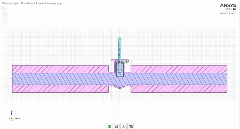
GEOMETRY:
- The geometry is imported into the spaceclaim.
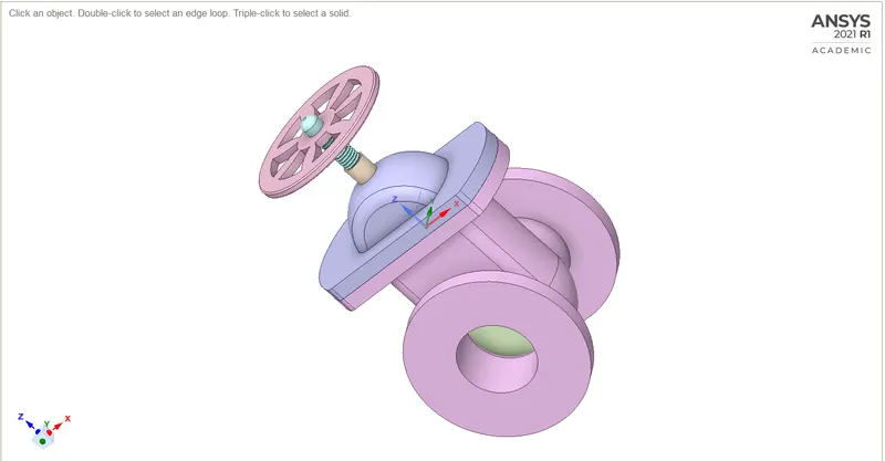
- Then the gate disc component is selected and given a lift of 10mm by using move tool available in the Ansys spaceclaim and the lift is parameterize.
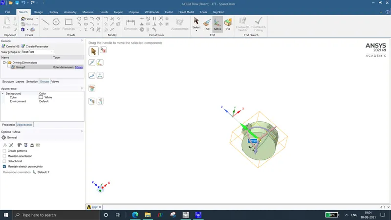
- Then the inlet and outlet is faces are pulled upto a distance of 800mm.
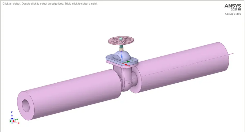
- Then the fluid volume is extracted from the model by using the volume extraction tool available in Ansys spaceclaim.
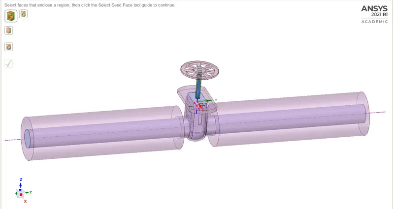
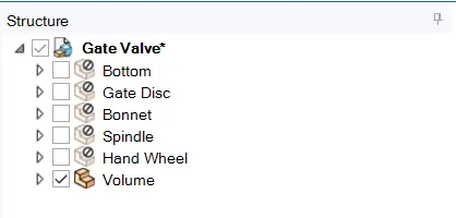
- Then the solid components are suppresed for physics.
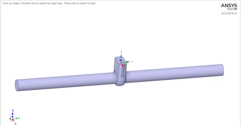
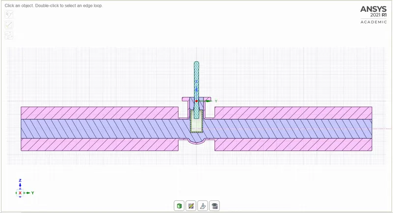
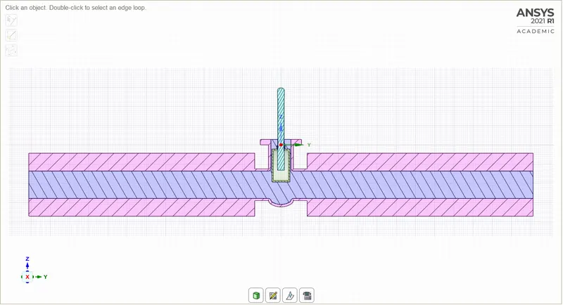
- The final geometry obtained will look like the image shown below
MESHING:
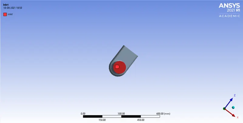
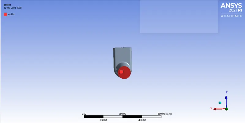
- The inlet and outlet named selection are created for left and right faces of the model as shown below.
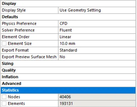
- The mesh size of 10mm is applied to the model.
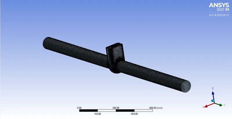
- The final meshed model will look like the image as shown below.
SETUP:
GENERAL:
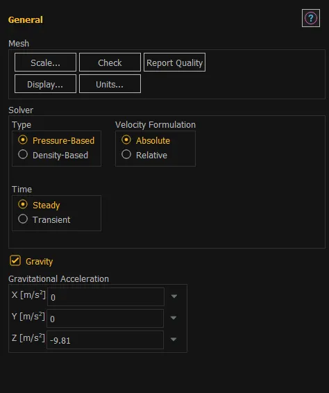
- Analysis type – steady state
- Solver – pressure based
- Gravity – 9.81m/s2 in z direction
MODEL:
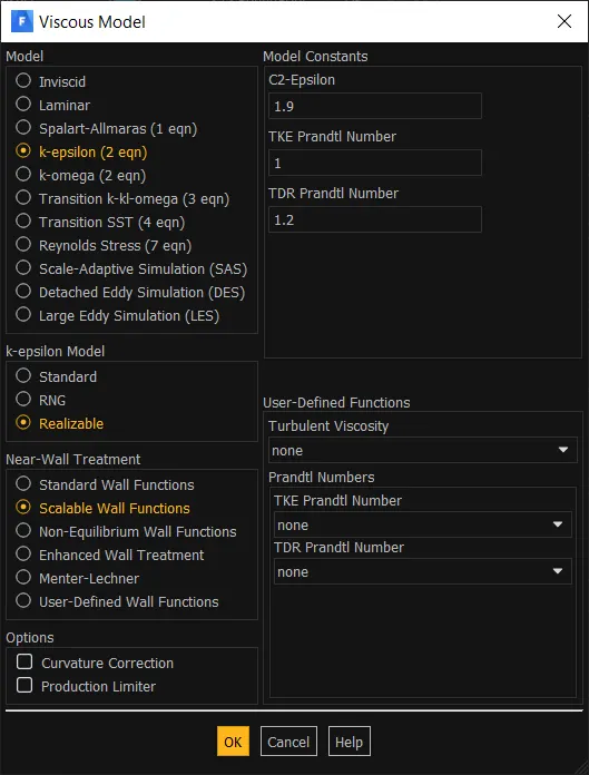
- Viscous – realizable k-epsilon with scalable wall function
MATERIAL:
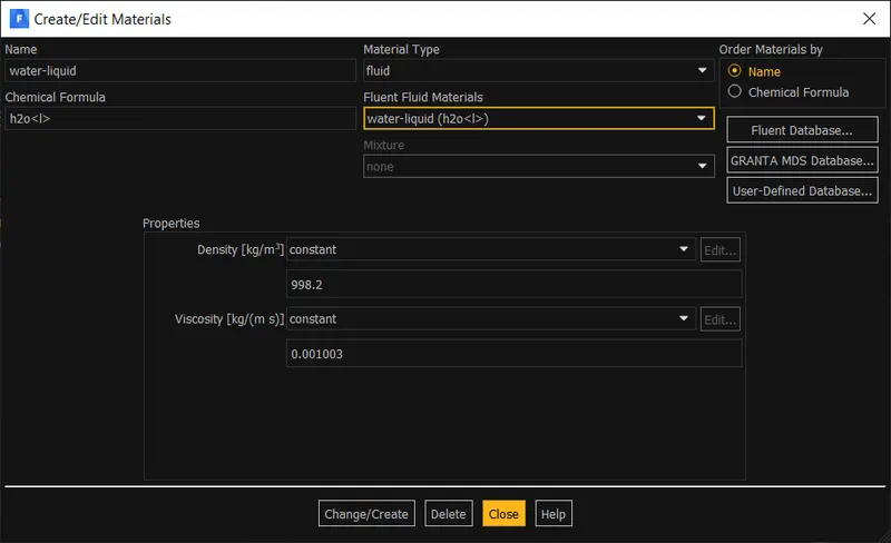
- Fluid – water liquid
CELLZONE:
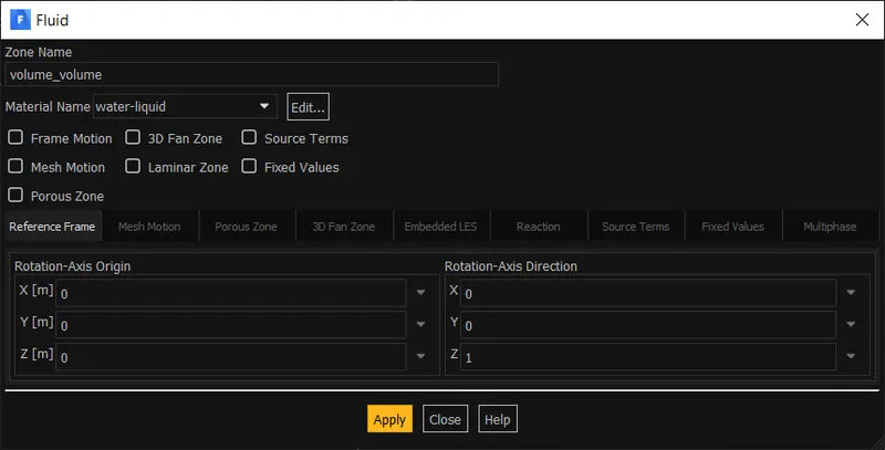
- Fluid - water-liquid
BOUNDARY CONDITION:
INLET:
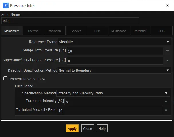
- Pressure inlet – gauge total pressure : 10 pa
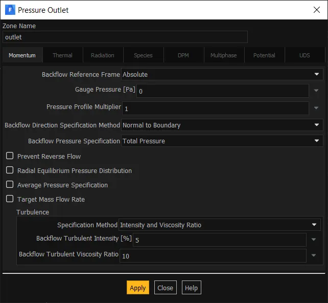
OUTLET:
- Pressure outlet – gauge total pressure : 0 pa
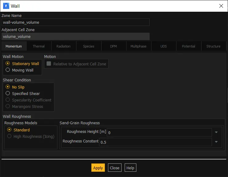
WALL:
- Wall – no slip stationary wall.
INTERIOR:
- Interior

INITIALIZATION:
Standard initialization.

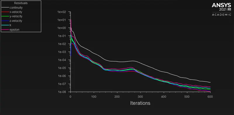
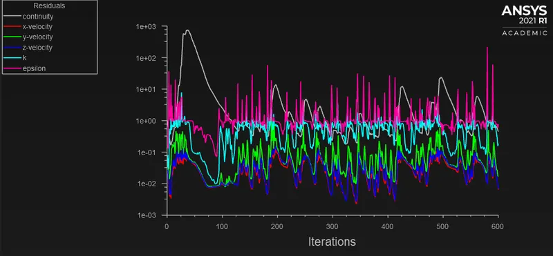
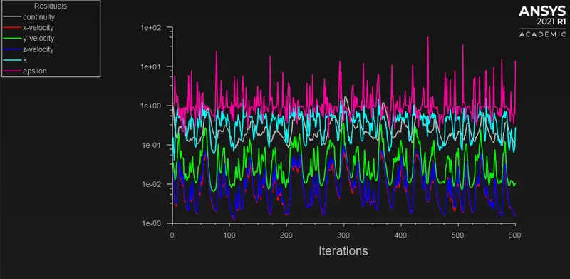
The simulation is runned for 600 iterations.
RESULTS:
CASE 1 – LIFT = 10MM:
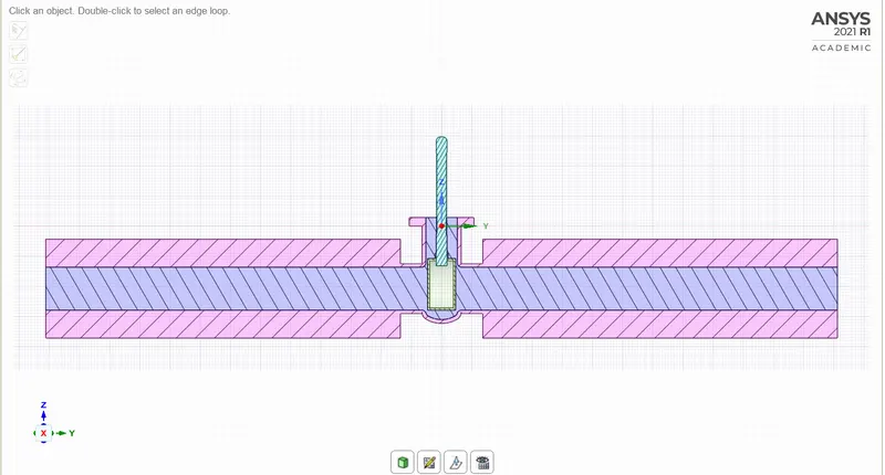
SECTIONAL VIEW:
RESIDUAL:
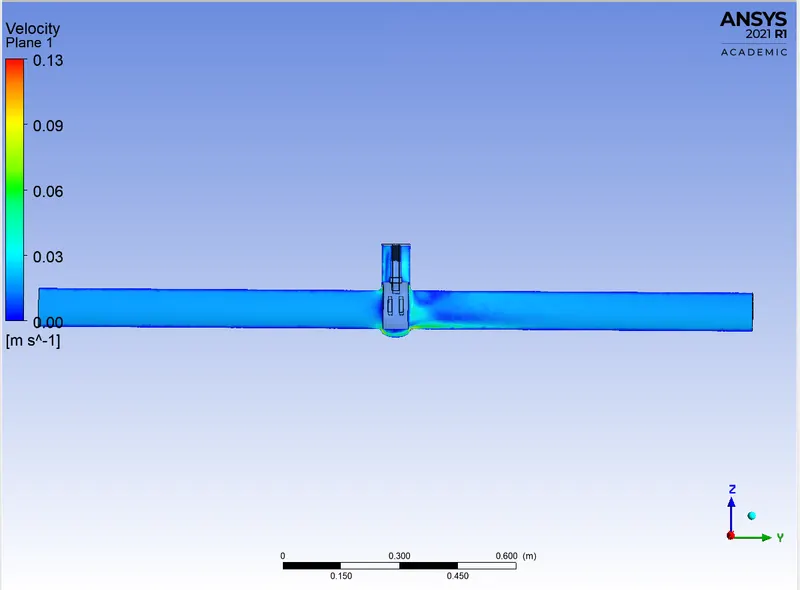
VELOCITY CONTOUR:
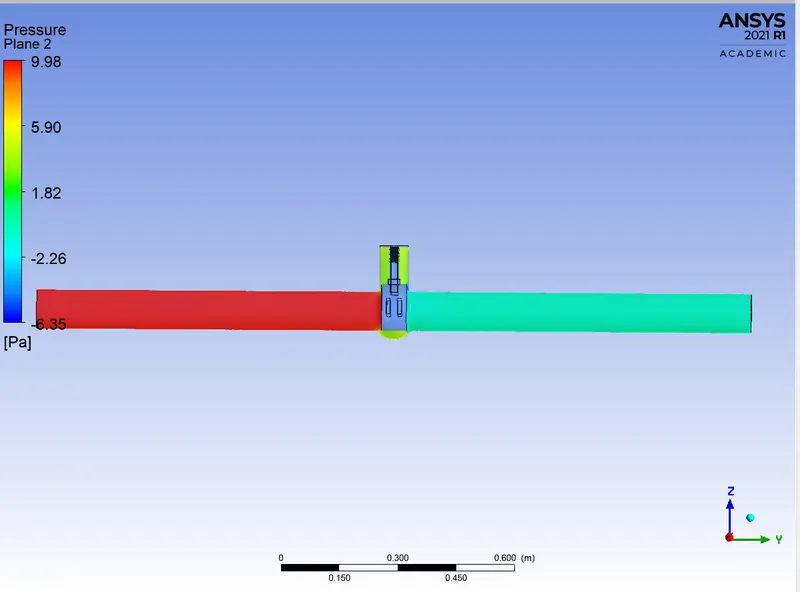
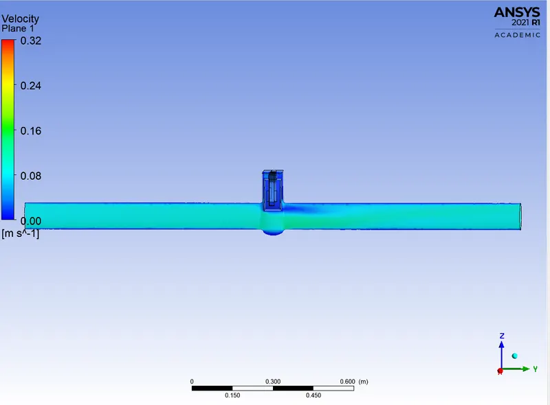
PRESSURE CONTOUR:
MASS FLOW RATE:
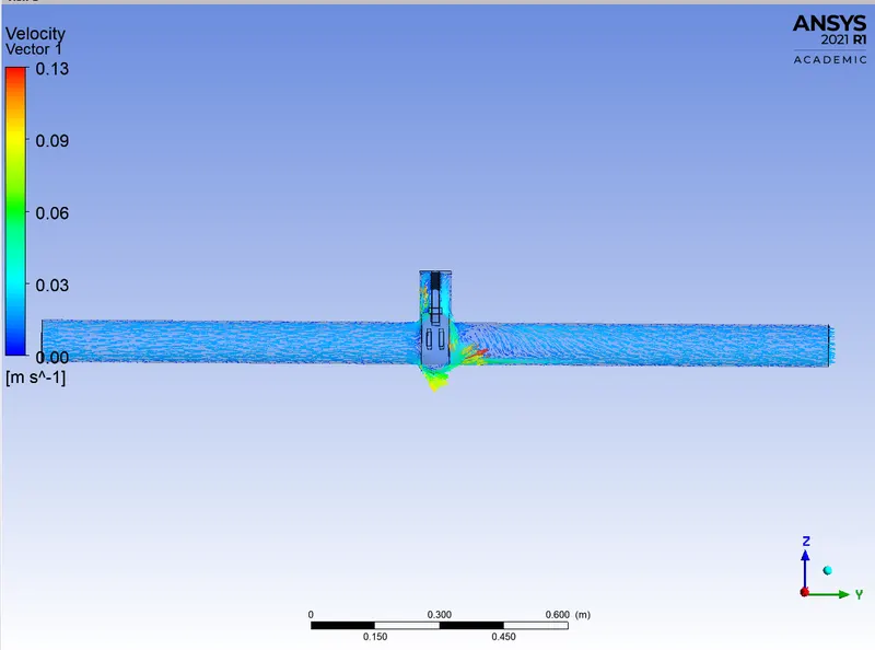
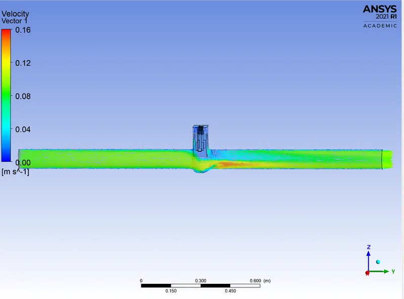
VELOCITY VECTOR:
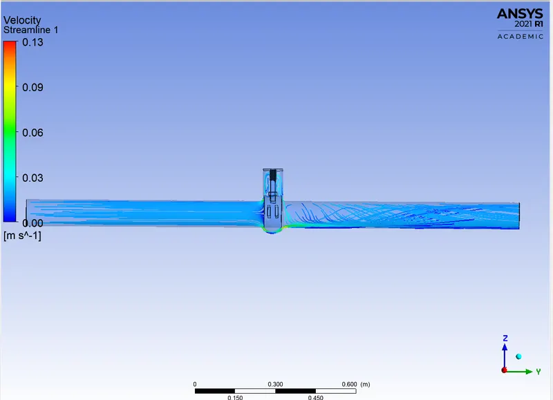
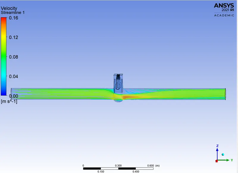
VELOCITY STREAMLINE:
CASE 2 – LIFT = 20MM:
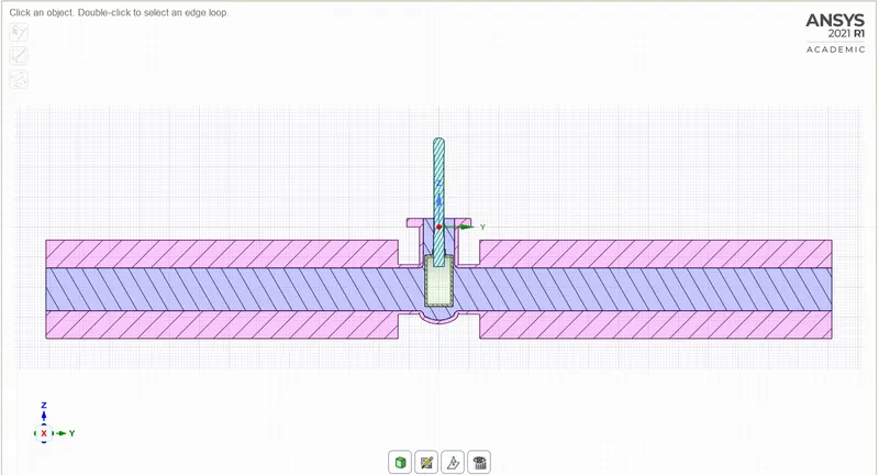
SECTIONAL VIEW:
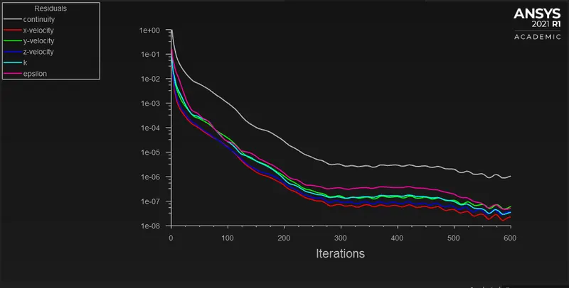
RESIDUAL:
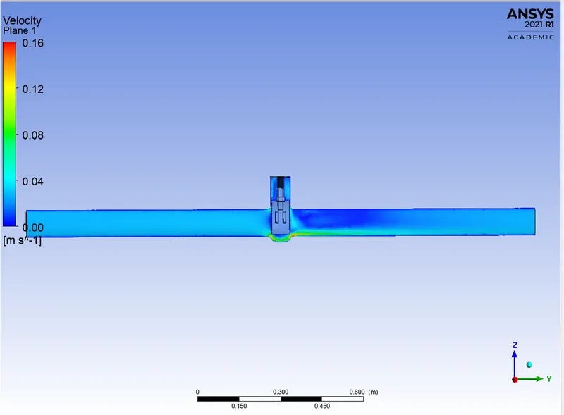
VELOCITY CONTOUR:
PRESSURE CONTOUR:
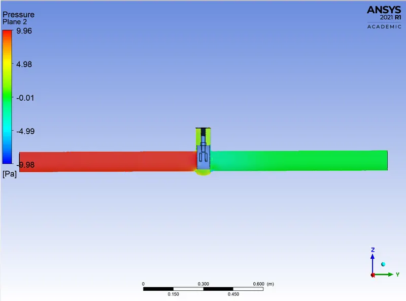
MASS FLOW RATE:
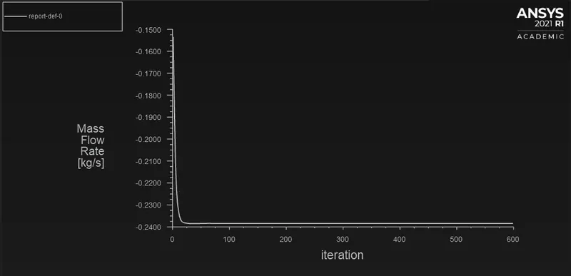
VELOCITY VECTOR:
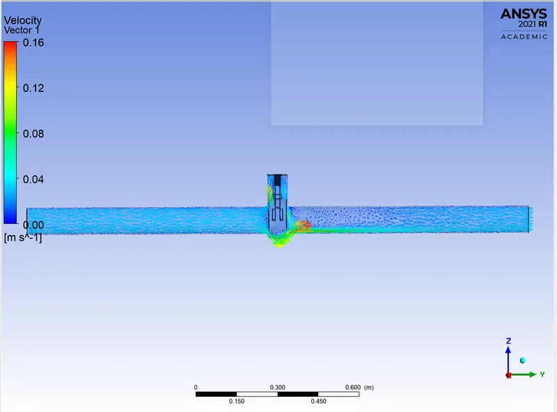
VELOCITY STREAMLINE:
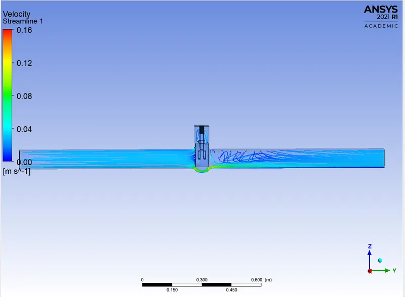
CASE 3 – LIFT = 30MM:
SECTIONAL VIEW:
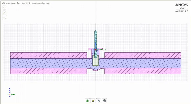
RESIDUAL:
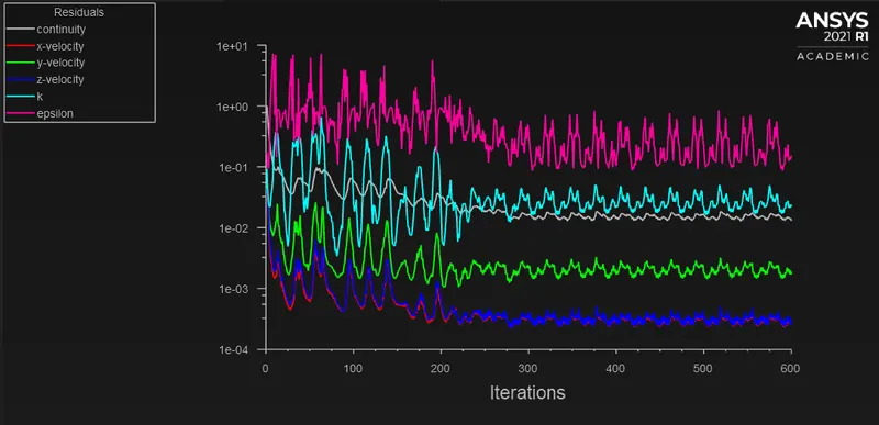
VELOCITY CONTOUR:
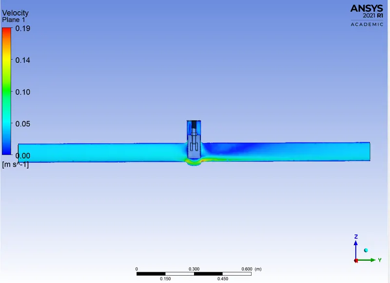
PRESSURE CONTOUR:
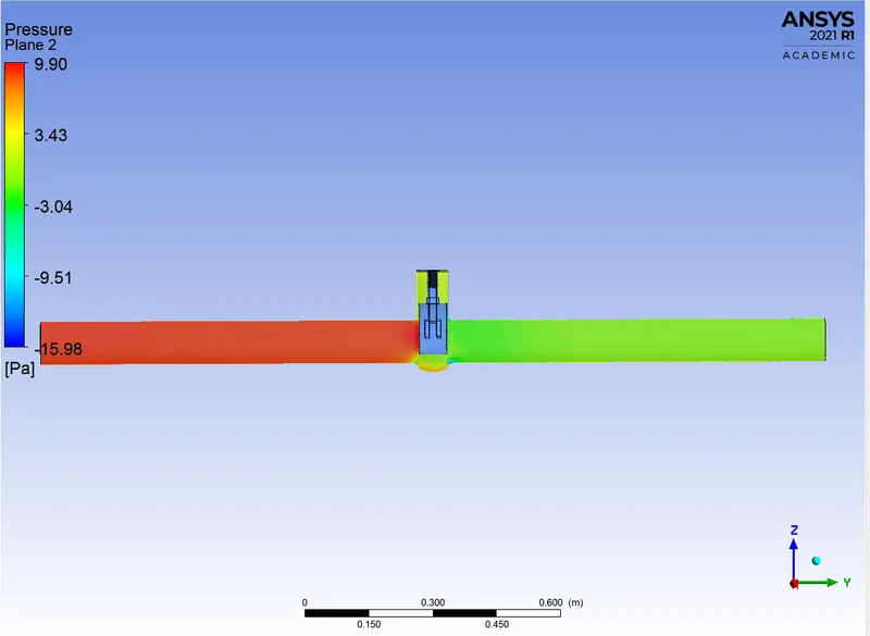
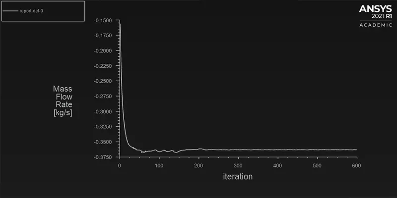
MASS FLOW RATE:
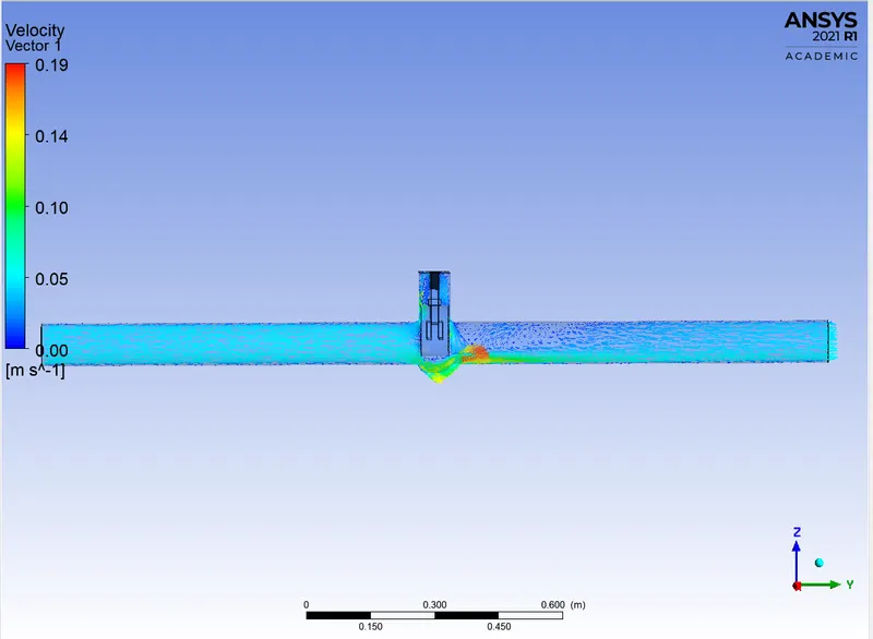
VELOCITY VECTOR:
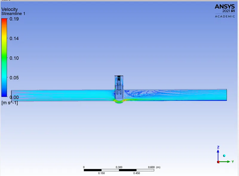
VELOCITY STREAMLINE:
CASE 4 – LIFT = 40MM:
SECTIONAL VIEW:
RESIDUAL:
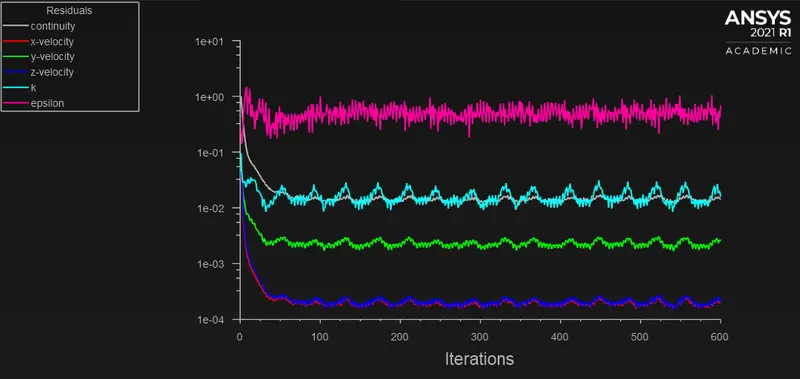
VELOCITY CONTOUR:
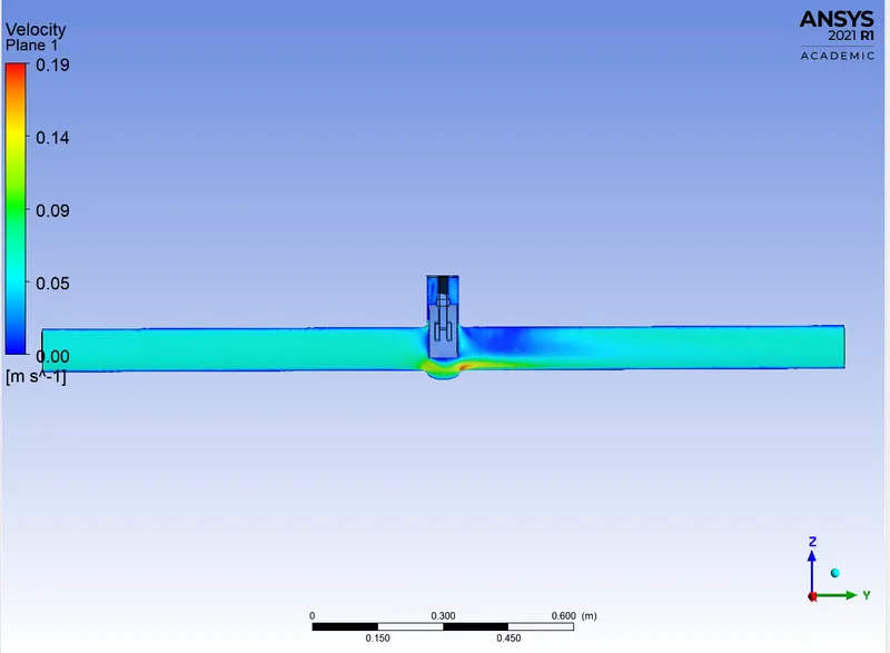
PRESSURE CONTOUR:
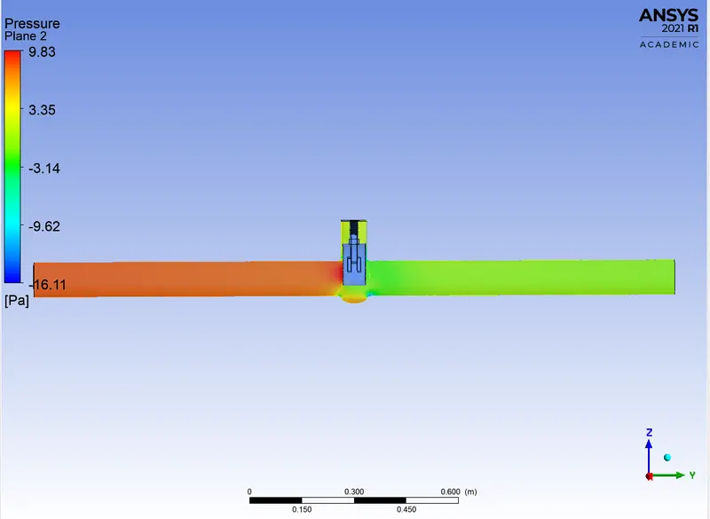
MASS FLOW RATE:
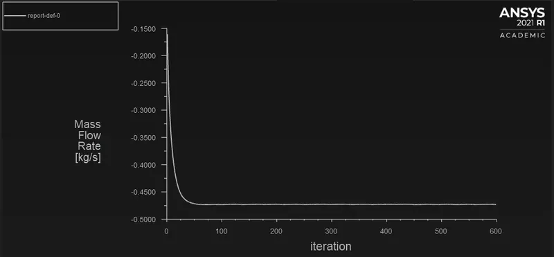
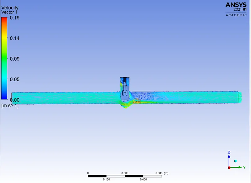
VELOCITY VECTOR:
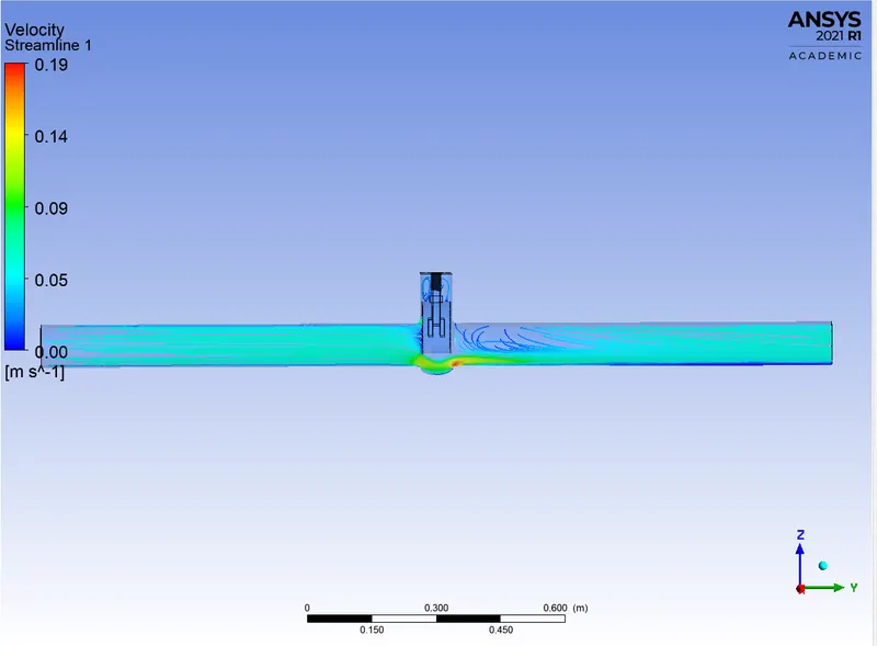
VELOCITY STREAMLINE:
CASE 5 – LIFT = 50MM:
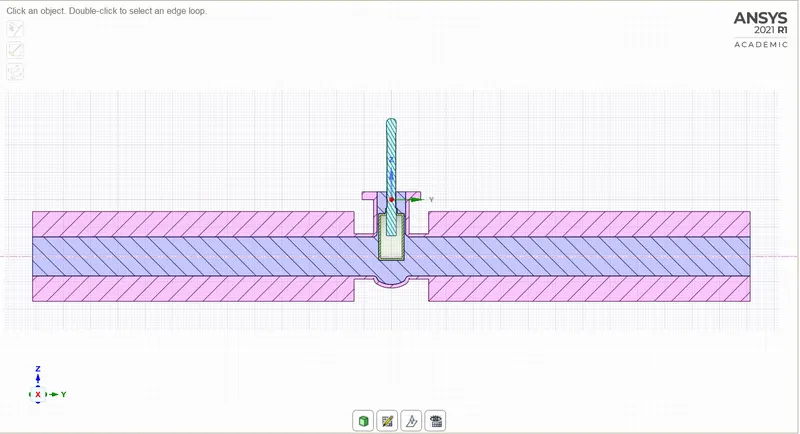
SECTIONAL VIEW:
RESIDUAL:
VELOCITY CONTOUR:
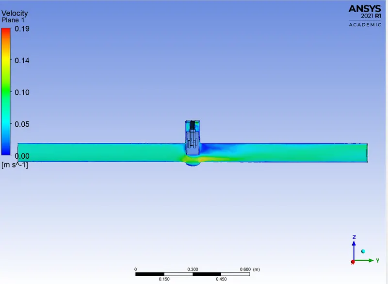
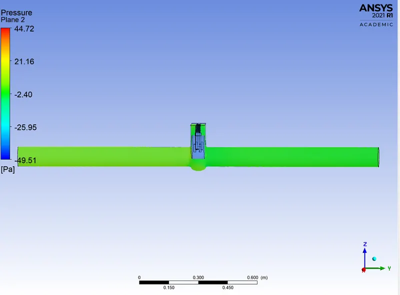
PRESSURE CONTOUR:
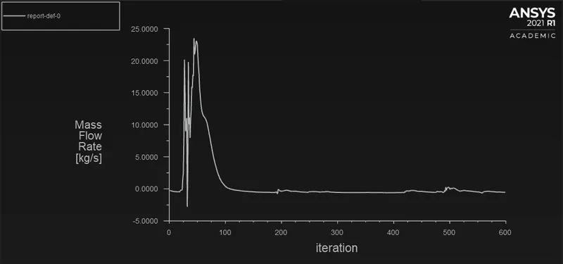
MASS FLOW RATE:
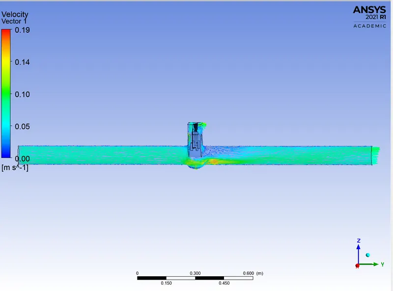
VELOCITY VECTOR:
VELOCITY STREAMLINE:
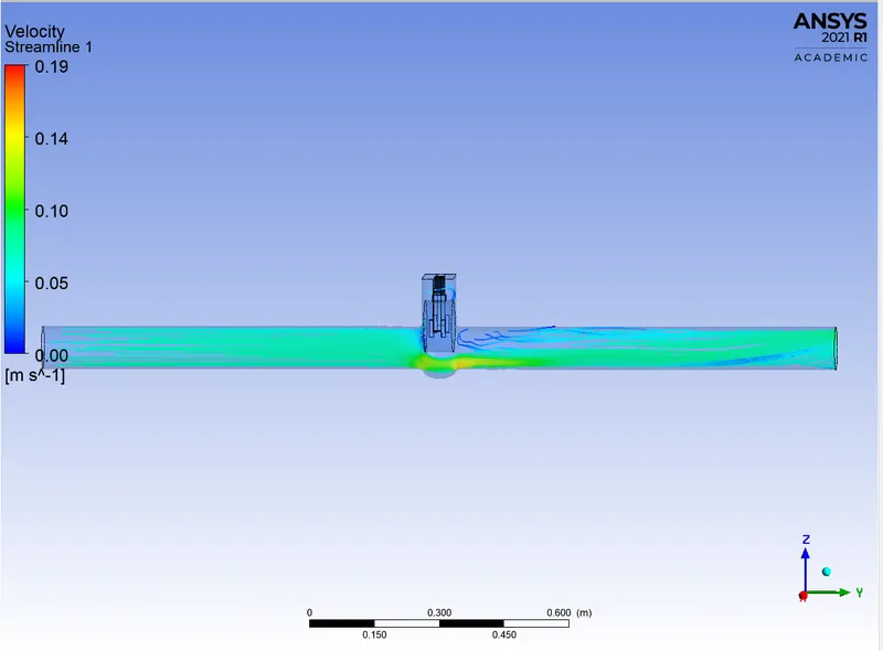
CASE 6 – LIFT = 60MM:
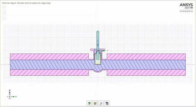
SECTIONAL VIEW:
RESIDUAL:
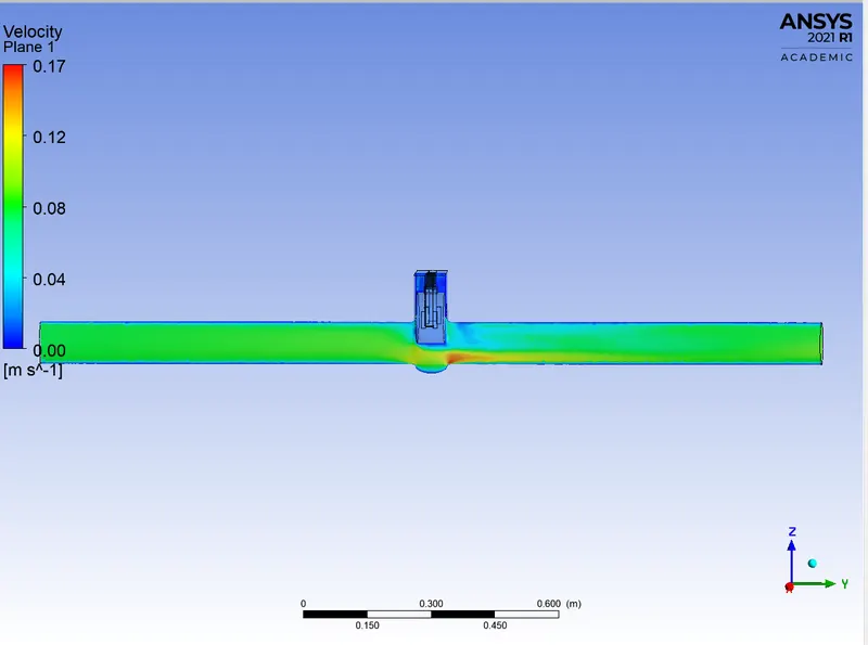
VELOCITY CONTOUR:
PRESSURE CONTOUR:
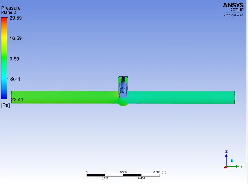
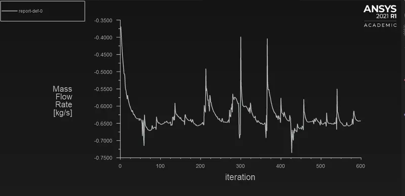
MASS FLOW RATE:
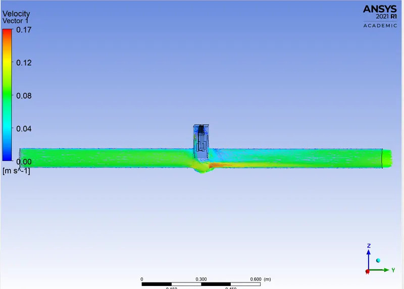
VELOCITY VECTOR:
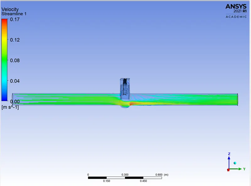
VELOCITY STREAMLINE:
CASE 7 – LIFT = 70MM:
SECTIONAL VIEW:
RESIDUAL:

VELOCITY CONTOUR:
PRESSURE CONTOUR:
MASS FLOW RATE:
VELOCITY VECTOR:
VELOCITY STREAMLINE:
CASE 8 – LIFT = 80MM:
SECTIONAL VIEW:
RESIDUAL:

VELOCITY CONTOUR:
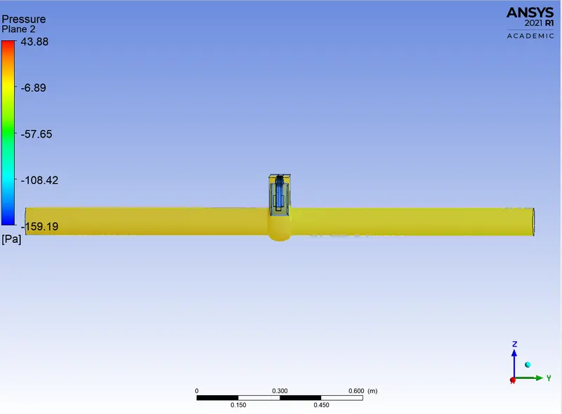
PRESSURE CONTOUR:
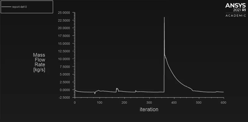
MASS FLOW RATE:
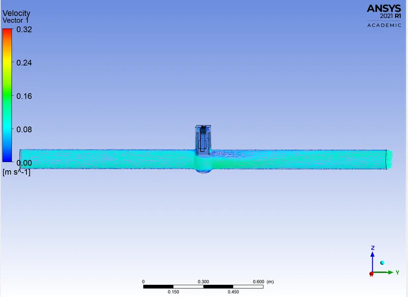
VELOCITY VECTOR:
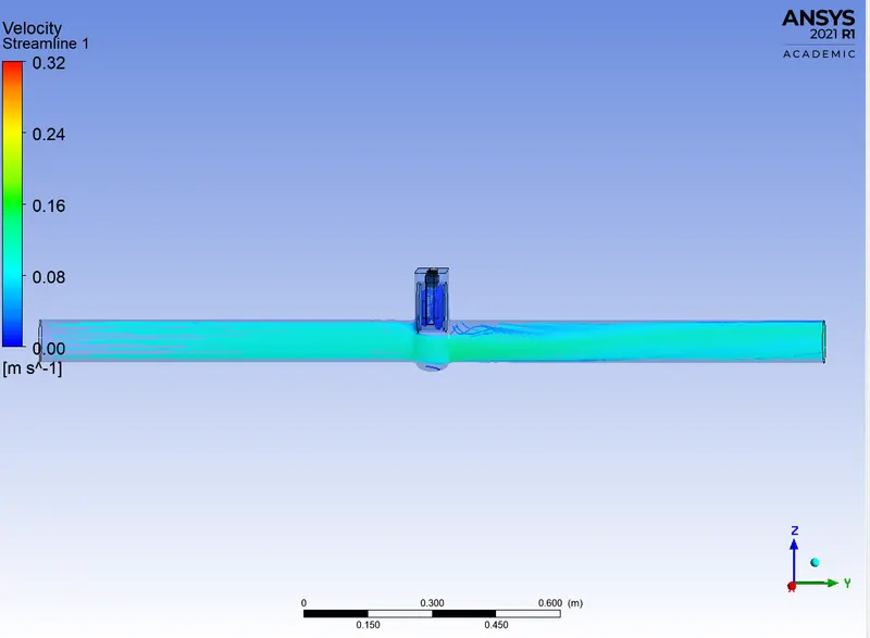
VELOCITY STREAMLINE:
MASS FLOW RATE PARAMETRIC RESULTS:
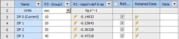

SUMMARY:
|
CASES |
LIFT [mm] |
MASS FLOW RATE [kg/s] |
FLOW COEFFICIENT |
FLOW FACTOR |
|
CASE 1 |
10mm |
-0.14932 |
0.749 |
0.648 |
|
CASE 2 |
20mm |
-0.23848 |
1.195 |
1.034 |
|
CASE 3 |
30mm |
-0.36328 |
1.821 |
1.576 |
|
CASE 4 |
40mm |
-0.47318 |
2.372 |
2.052 |
|
CASE 5 |
50mm |
-0.54292 |
2.723 |
2.355 |
|
CASE 6 |
60mm |
-0.64295 |
3.222 |
2.787 |
|
CASE 7 |
70mm |
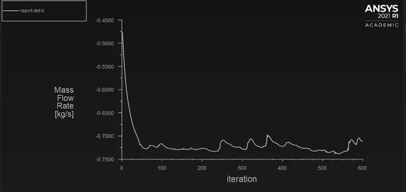
-0.71213 |
3.570 |
3.088 |
|
CASE 8 |
80mm |
-0.7555 |
3.785 |
3.274 |
GRAPH:
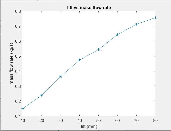
LIFT VS MASS FLOW RATE:
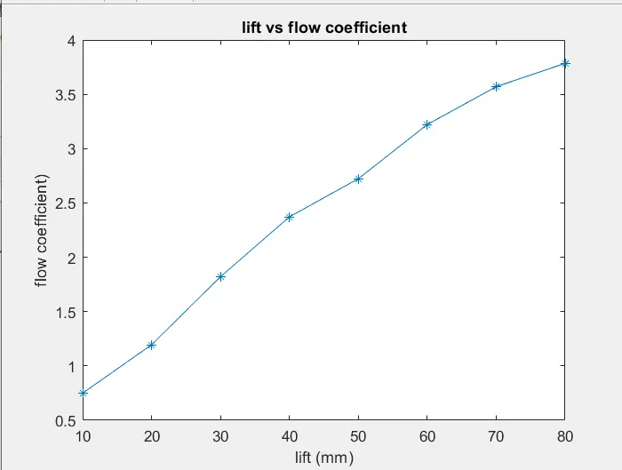
LIFT VS FLOW COEFFICIENT:
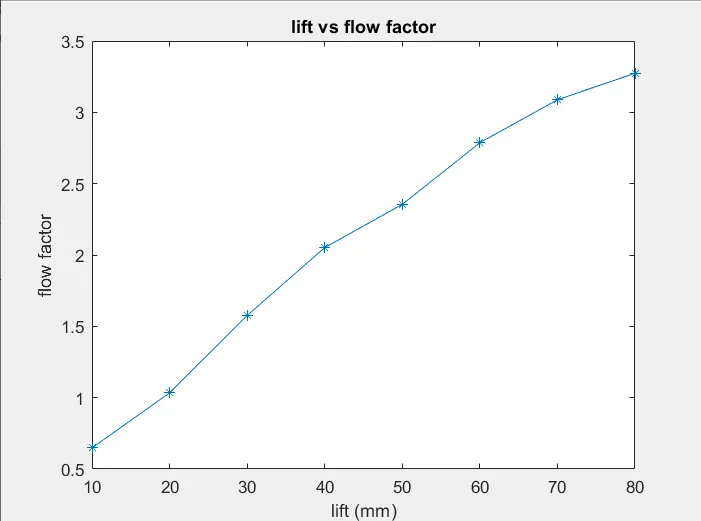
LIFT VS FLOW FACTOR:
OBSERVATION FROM GRAPHS:
- As the lift of gate valve increases, mass flow rate increases.
- With increase in mass flow rate, there is increase in flow coefficient.
- Flow factor also increases with increase in valve lift.
- The mass flow rate, flow coefficient and flow factor increases linearly with respect to gate disc opening.
CONCLUSION:
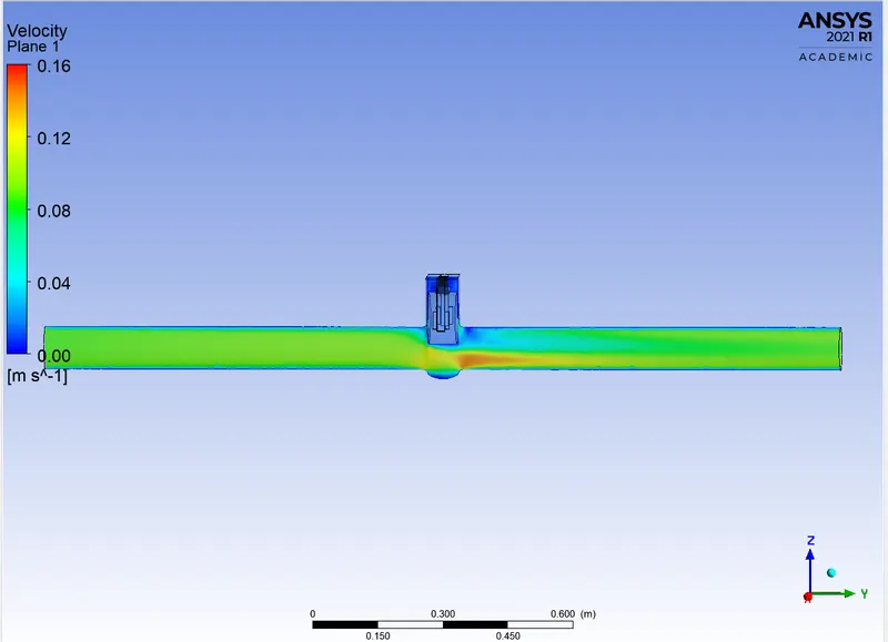
- From the observations we can conclude that the velocity is less when gate valve lift is 10mm. As the opening or lift of gate disc increases velocity of flow increases.
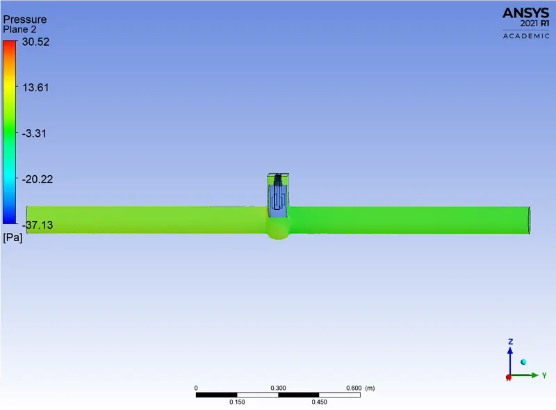
- The pressure is high at the inlet side and lower at the outlet side thus the flow takes place due to pressure difference.
- There is gradual increase in mass flow rate, flow coefficient and flow factor as the gate valve disc lift increases.
- When the valve is fully open mass flow rate and flow coefficient and flow factor becomes maximum.