Week 9 - Parametric study on Gate valve.
Aim: To perform a parametric study on the gate valve simulation by varying the valve position using ansys 2021 r1.
Introduction:
Gate valve is a control device used to control the flow of fluid through a pipe or opening.It controls the flow by restricting or allowing the portion of flow.There are many kinds of valves in fluid dynamics study classified on shape ,usage and what they contol some important ones based on control are pressure control valve,flow control valve.There are manually operated valves and automatic valves mostly used as pressure relief valve which activates when predetermined pressure is reached. Manually controlled valves are in vast usage all over the world for many years.They are used in house holds for controlling the flow of water,gas etc.Most common flow control valve is gate valve it consists of gate,spindle and a wheel to rotate.The gate can be lifted up and down to control the flow.The gate is present perpendicular to the axis of the pipe.
In this report we are going to discuss the flow parameters that are affected by the position of the gate valve.
Mass flow rate:
Mass flow rate is defined as the amount fluid flown per given time.It is measured in kg/s.Direct mass flow measurement is very useful improvement in the vast industry as it removes errors caused by the physical properties of the fluid.The mass of fluid comming out of pipe is not affected by changing temperature and pressure.
It is denoted by  .
.
Its units are kg/s
Problem solving and modelling approach:
Geometry setup:
Import the valve into the space claim
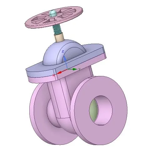
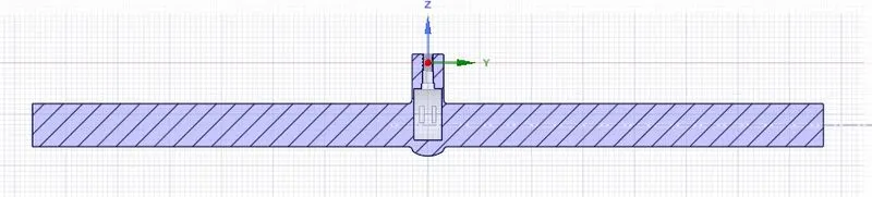
- The gate is adjusted to the required position
- parameter grouping is done to the gate and reqired position is set from the grouping.
Extraction:
- The fluid volume is extracted by selecting the edges.
- extend the fluid volume on both sides for 800mm on both sides.
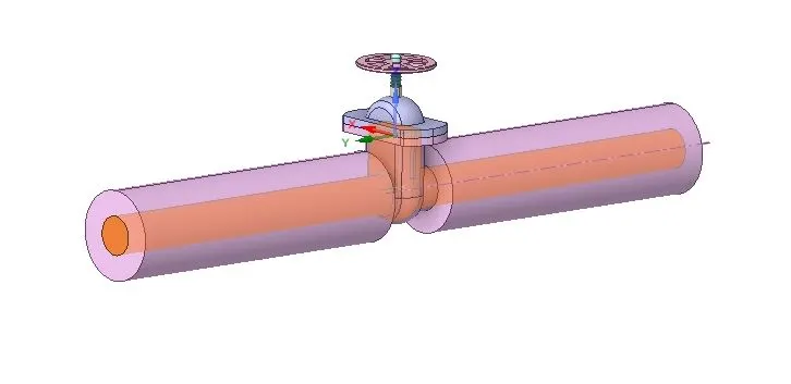
Fluid volume:
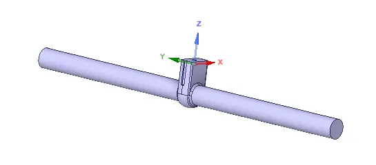
- The parts other than the fluid volume is supressed for physics.
If the opening of gate is changed we can click on the volume and click set as current contex the fluid adjusts itself to the gate opening.
Meshing:
In the meshing the best mesh possible for simulation in which number of cells are within the limits of the academic version of ansys.
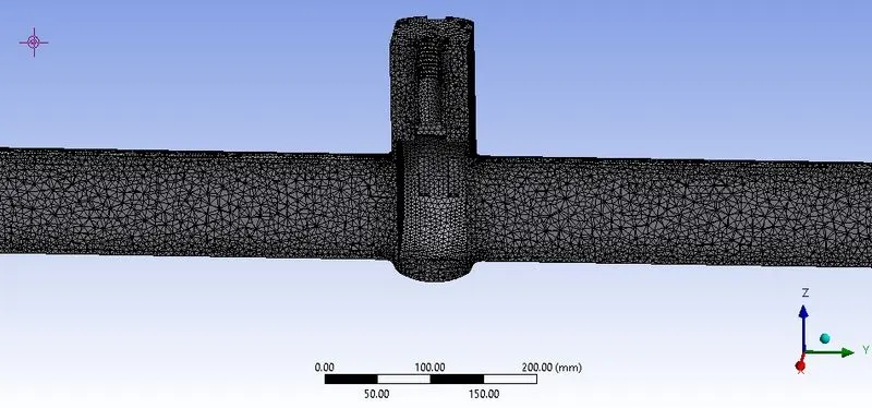
element size: 5.4mm
No of elements:508998
- Naming of inlet and outlet is given
Pre-processing:
- Fluent is opened and gravity is set to -9.81 in z direction.
- viscous model is selected as k -epsilon with realizable and scaled wall function.
- from materials copy water and in cell zones add water to the fluid and remove the air.
Creating plots and contours:
- In definitions flux report add mass flow rate and create a plane along the pipe to view the contours.
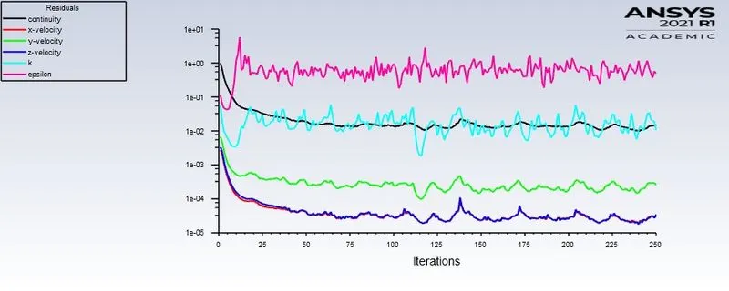
- In contours give pressure and velocity on the created plane.Simulation is ru for 250 iterations after initializing as staandard from the inlet.
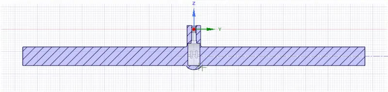
case 1:Gate opening 10mm
gate valve position:
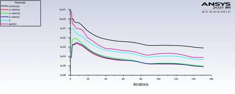
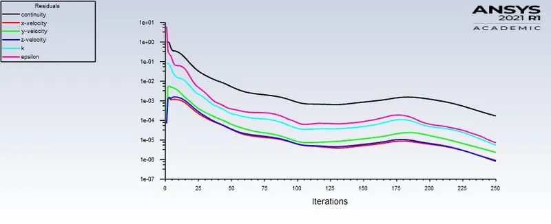
Residulas:
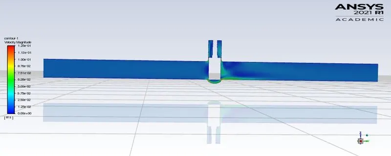
Velocity contour:
Pressure contour:
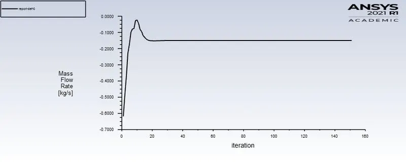
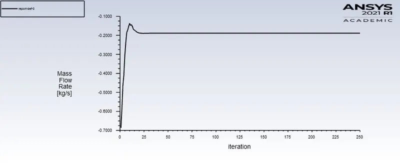
mass flow rate:
case 2:Gate opening 15mm
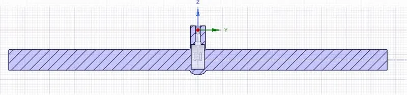
gate valve position:
Residuals:
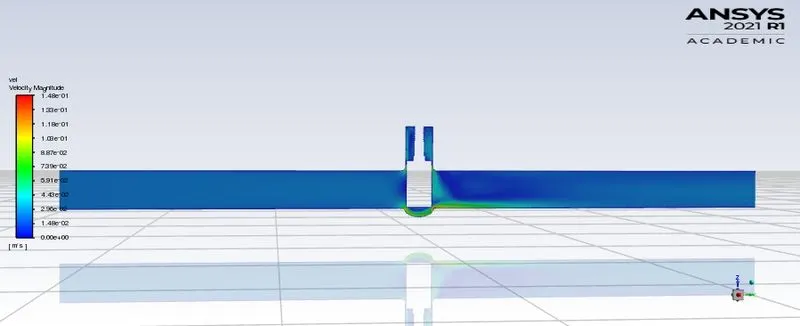
Velocity contour:
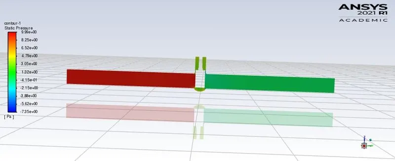
Pressure contour:
Mass flow rate:
case 3:Gate opening 25mm
gate valve position:
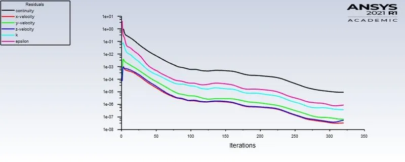
Residulas:
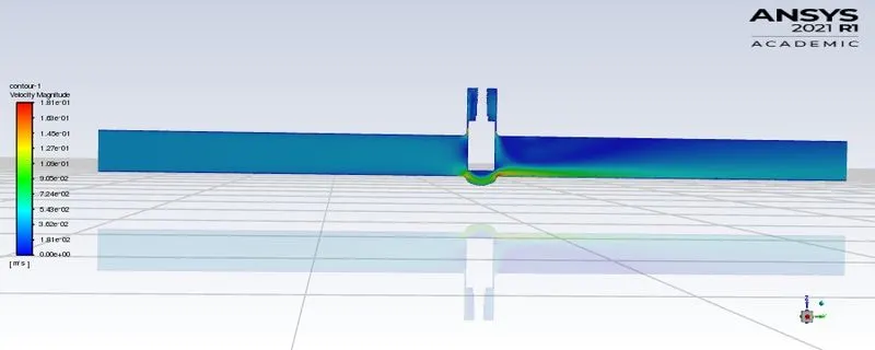
Velocity contour:
Pressure contour:
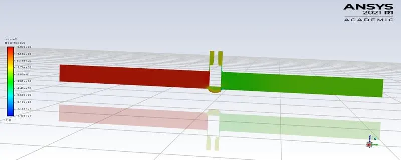
mass flow rate:
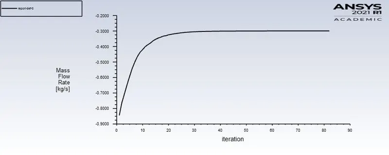
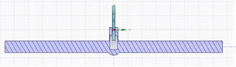
case 4:Gate opening 35mm
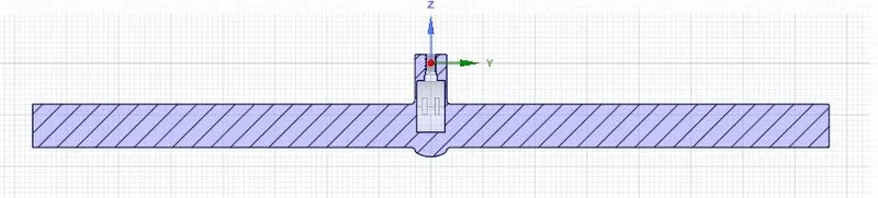
gate valve position:
Residulas:
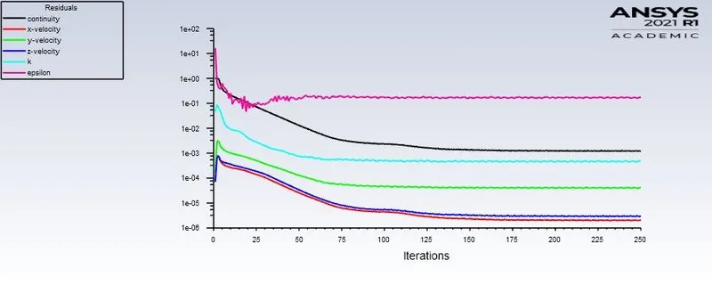
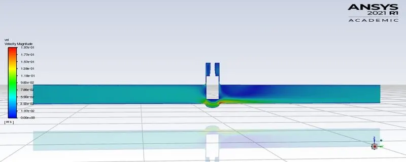
Velocity contour:
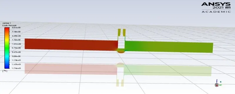
Pressure contour:
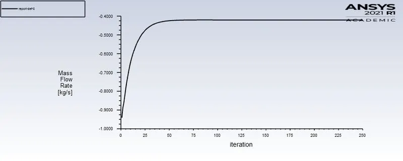
mass flow rate:
case 5:Gate opening 45mm
gate valve position:
Residulas:
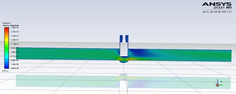
Velocity contour:
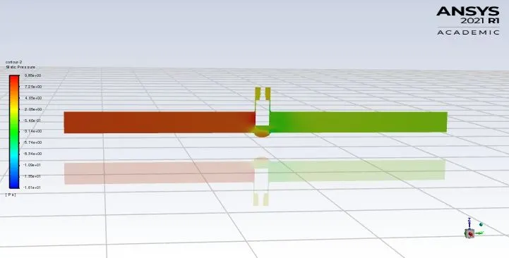
Pressure contour:
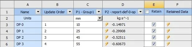
Parametric study:

Flow coefficient:
Flow coefficient is measure of the capacity or relative efficiency of a valve.It takes into consideration the pressure drop the specific gravity of fluids and flow rates.It is an important paarameter in sizing the valve.
Flow factor is denoted by `C_v`
`C_v = Q*sqrt((SG)/(DeltaP))`
Q is the mass flow rate in Gallons per minute
SG is the specific gravity of fluid flowing through valve(SG of water is 1)
`DeltaP`is the pressure drop across the valve
Flow factor:
Flow factor is the same as the flow coefficient the only difference is in the units .it is in metric units
`K_v`=0.865*`C_v`
Table showing different parameters for different gate disk openings
| Gate position(lift) | Max velocity(m/s) | Mass flow rate (kg/s) | Mass flow rate(GPM) | Pressure drop(psi) | flow coefficient(`C_v`) | Flow factor(`K_v`) |
| 10 | 0.125 | 0.14971 | 2.37 | 8.66 | 67 | 57.955 |
| 15 | 0.148 | 0.18852 | 2.99 | 7.96 | 87.9 | 75.25 |
| 25 | 0.181 | 0.29908 | 4.74 | 6.17 | 158 | 136.67 |
| 35 | 0.197 | 0.4218 | 6.69 | 5.23 | 242 | 209 |
| 45 | 0.208 | 0.52511 | 8.32 | 4.71 | 318 | 275 |
Conclusion:
- It is observed that the mass flow rate increased with the increase in the lift of gate disk.As this allows the fluid to be less restricted flow.
- As the gate lift is increassed the pressure drop is also decreased.
- With the decrease in the pressure drop the flow coefficient increases as it is inversely proportional to the pressure drop.
- Velocity is increased with the increase in the lift of the gate.
Referances:https://www.burkert.com/en/Service-Support/Support/Glossary/Fluid-Calculator