Week 9 - Parametric study on Gate valve.
Aim: To understand the flow through the valve and calculate the flow parameters required to estimate the difference in valve lift.
Objective:
- To simulate gate valve.
- Estimate flow parameters.
- To carry out parametric study.
GATE VALVE FUNCTION :
-
Gate valves are used to shut off the flow of liquids rather than for flow regulation.
-
When fully open, the typical gate valve has no obstruction in the flow path, resulting in very low flow resistance.
-
The size of the open flow path generally varies in a nonlinear manner as the gate is moved. This means that the flow rate does not change evenly with stem travel.
-
Depending on the construction, a partially open gate can vibrate from the fluid flow.Gate valves are mostly used with larger pipe diameters (from 2" to the largest pipelines) since they are less complex to construct than other types of valves in large sizes.
-
At high pressures, friction can become a problem. As the gate is pushed against its guiding rail by the pressure of the medium, it becomes harder to operate the valve. Large gate valves are sometimes fitted with a bypass controlled by a smaller valve to be able to reduce the pressure before operating the gate valve itself.
-
Gate valves without an extra sealing ring on the gate or the seat are used in applications where minor leaking of the valve is not an issue, such as heating circuits or sewer pipes.
Flow Coefficient :
- Valve Flow Coefficient (Cv) is a valve’s capacity for a liquid or gas to flow through it.
- It is technically defined as “the volume of water at 60°F (in US gallons) that will flow through a valve per minute with a pressure drop of 1 psi across the valve.”
- In simpler terms, the larger the opening in a valve, the larger the Cv. As a valve is opening, the Cv increases until the valve is fully open, where it reaches its highest possible Cv, or 100% open Cv.
- The flow coefficient of a device is a relative measure of its efficiency at allowing fluid flow.
- It describes the relationship between the pressure drop across an orifice valve or other assembly and the corresponding flow rate.
- In more practical terms, the flow coefficient Cv is the volume (in US gallons) of water at 60 °F (16 °C) that will flow per minute through a valve with a pressure drop of 1 psi (6.9 kPa) across the valve.
- The use of the flow coefficient offers a standard method of comparing valve capacities and sizing valves for specific applications that is widely accepted by industry.
- The general definition of the flow coefficient can be expanded into equations modeling the flow of liquids, gases and steam using the discharge coefficient.
- Mathematically it is expressed as,
`C_v=Q*sqrt(SG)/(DeltaP)`
Where,
Q = mass flow rate. (Gallons per minute)
SG = Specific Gravity.
`DeltaP` = Pressure Drop across the valve. (psi)
Flow factor:
- The kv factor of a valve indicates "The water flow in m3/h, at a pressure drop across the valve of 1 kgf/cm2 when the valve is completely open.
- The complete definition also says that the flow medium must have a specific gravity of 1000 kg/m3 and a kinematic viscosity of 10−6 m2/s. e.g. water.
- Mathematically it is expressed as,
`K_v = Q*sqrt((SG)/(DeltaP)`
`K_v`= Flow factor.
Q = mass flow rate.
SG = Specific Gravity.
`Delta P` = Pressure Drop across the valve.
It is also expressed as,
`K_v=0.865*C_v`
Simulation Procedure :
Simulation is carried for 8 different case setups :
- 10 mm
- 20 mm
- 30 mm
- 40 mm
- 50 mm
- 60 mm
- 70 mm
- 80 mm
- The mass flow rate at the outlet is compaired for different disc lift.
Creating Geometry :
- Load the geometry.
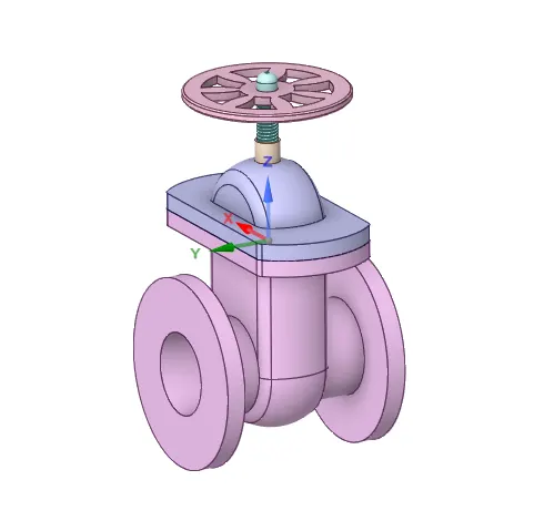
Increase the length of the pipe by 800 mm from both the sides by using 'Pull' tool.
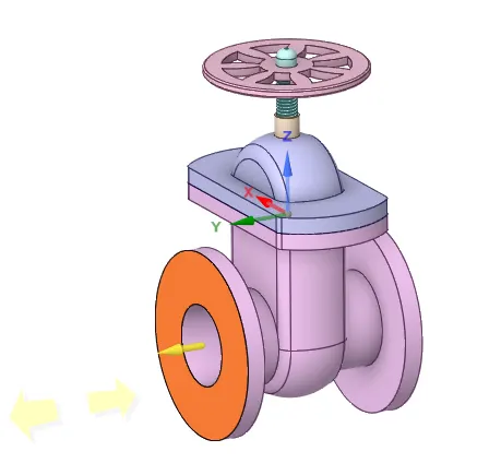
- Geometry after pulling,
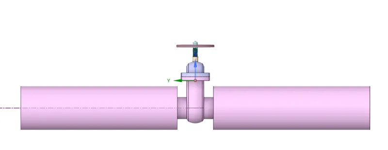
- Next step is to create the volume inside the valve setup.
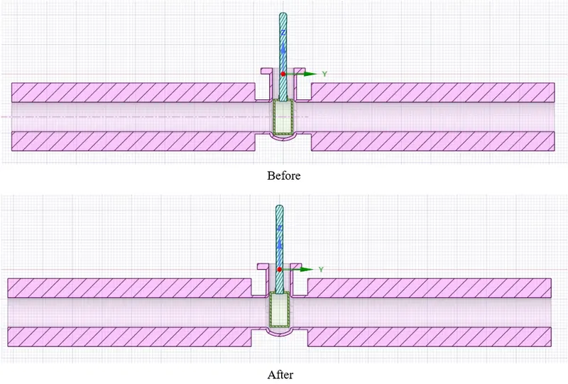
- Before creating the fluid volume, we must lift the dics by 10mm for the first case.
- This is done by selecting the Disc and the Spindle together and dragging it upwards and assigning the dimensions.
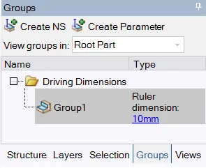
- Then go to groups and select 'Create Parameter'. This will only activiate after moving the component (disc and spindle).
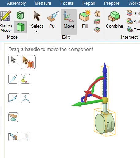
- Now we are ready to create the volume.
- Suppress the handle and bonnet.
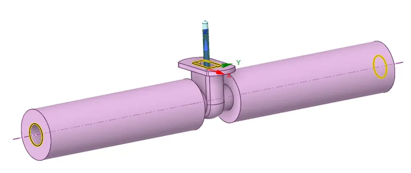
- Click on extract volume (Prepare). Select edge selection.
- Select the two extreme edges and the top edge to create the volume.
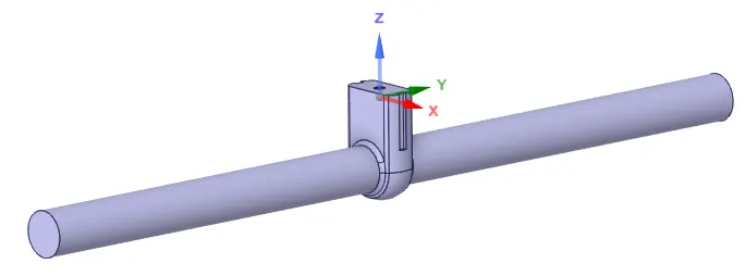
- Final volume should look like this:
- Below is the geometry for 20mm to 80 mm.
Case 1 -20 mm
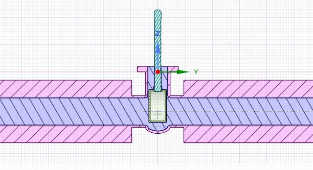
Case 2-30 mm
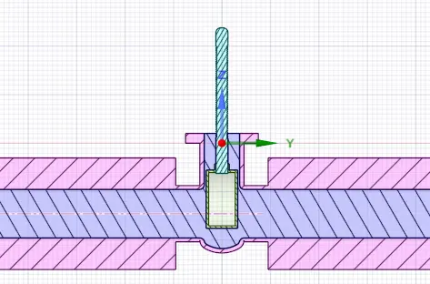
Case 3-40 mm
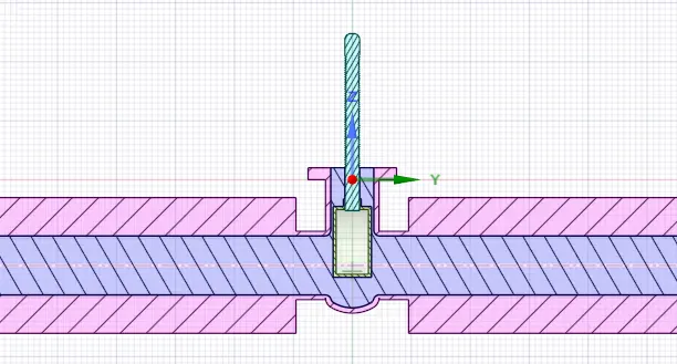
Case 4-50 mm
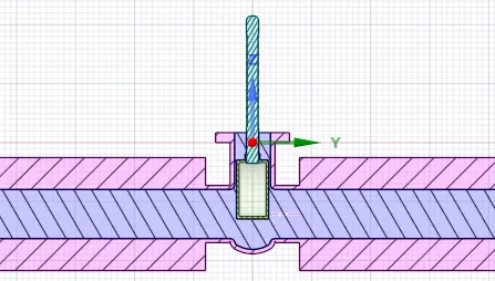
Case 5-60 mm
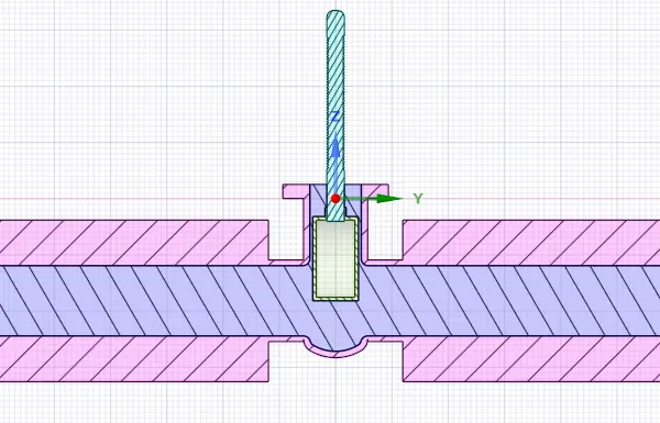
Case 6-70 mm
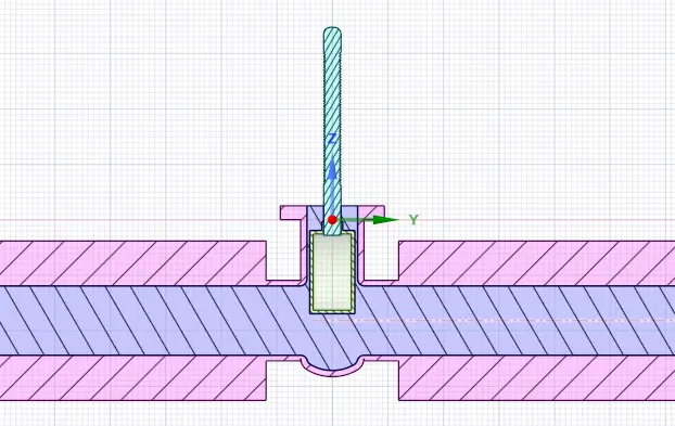
Case 7-80 mm
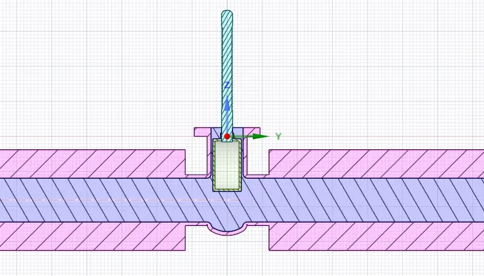
- The parametric study :
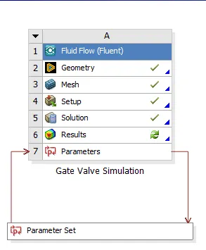
- Initially one must only create for 10 mm, and then start adding values to the parameter setup page. As shown below:
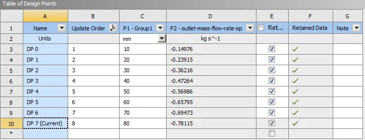
- This makes our task easier by just giving an input of different lift. The rest calculation is done by Ansys.
- This helps in easy comparison of wide variety of cases without even editing the volume manually.
Meshing:
- Meshing is same for all the cases.
- Before meshing, it is good practice to name the entities.
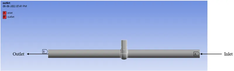
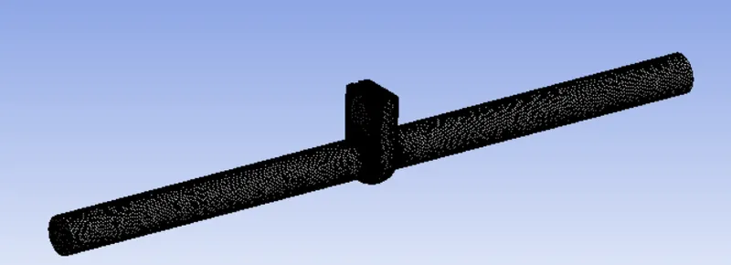
- Update the mesh.
Setting up the Physics:
- Carry out steady-state simulation.
- For this simulation the setup is quite easy.
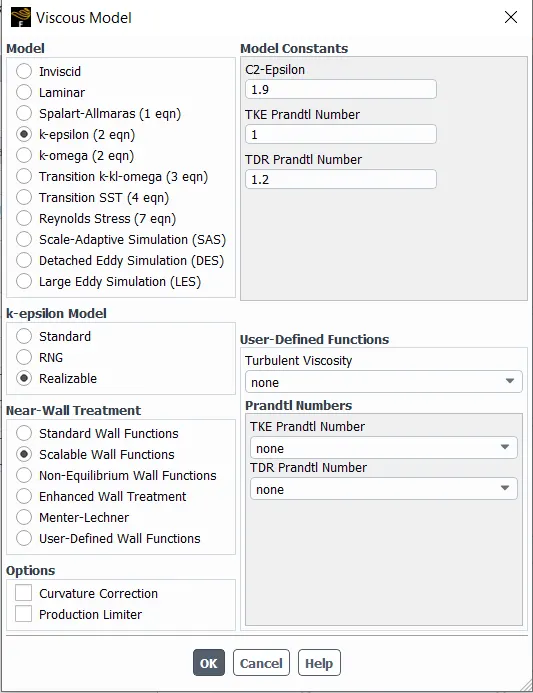
- Viscous model: k-epsilon, realizable, scalable wall function.
- Go to boundaries and select inlet boundary condition type as 'pressure-inlet' and a value of 10 Pa.
- This will help us in deciding whether the flow is turbulent or laminar.
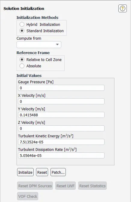
- But for Reynolds number we need the velocity of the free stream. This can be don with the help of Ansys initialization section.
- Select standard initialization and select compute from inlet. It will show the velocity.
- Therefore,
`R_e=(rho*U*D)/mu`
`rho = 998.2k(g)/m^3`
U = 0.1415 m/s
D = 0.1 m
μ">μμ = 0.00103
Substituting the values, Re = 13713.135 which is greater than 2000 for a flow to be turbulent.
- Initialize the solution and compute form inlet.
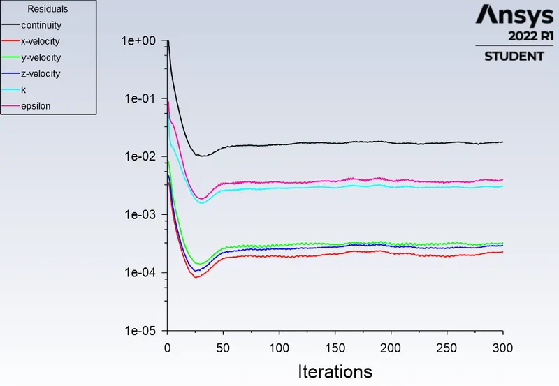
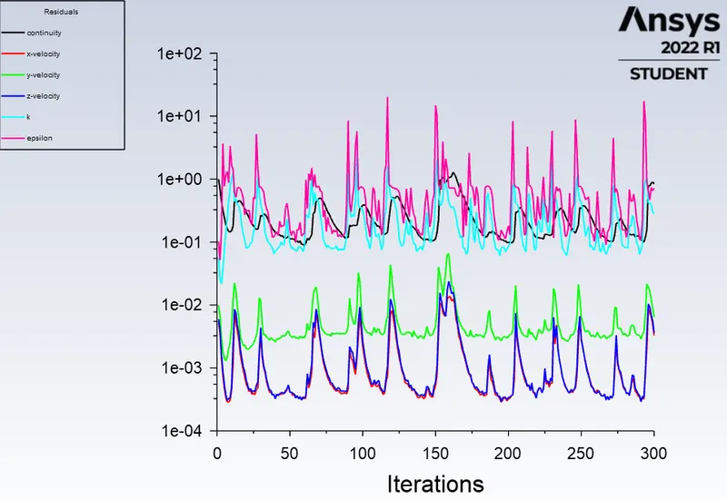
- Run the calculation for 300 iterations.
REAULTS :
Case 1 = 10 mm
- Residual Plot:
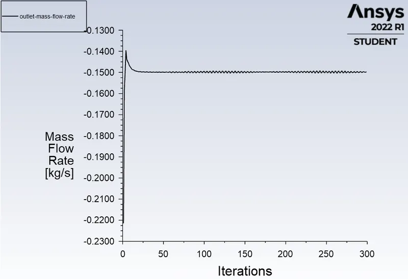
- Mass Flow Rate at outlet of the gate valve :

- Flow Coefficient and Flow Factor Calculation:
Flow coefficient:
Pressure Drop = Total pressure at inlet - Total pressure at outlet.
Therefore, △P">△P△P = 10 - 0 = 10 Pa
We need the pressure in terms of psi, conversion form Pascal to psi is 1Pa = 0.000145038 psi
So, 10 Pa = 0.00145038 psi.
Q = 0.1497 kg/s
Q is expressed in Gallons per minute (GPM).
Q in GPM = 3.21 GPM
Specific Gravity of water = 1
Therefore,
`C_v=Q*sqrt(SG)/(DeltaP`
Substituting the value,
`C_v` = 84.2987
Flow factor:
`K_v` = 0.865*`C_v`
`K_v`= 72.9183
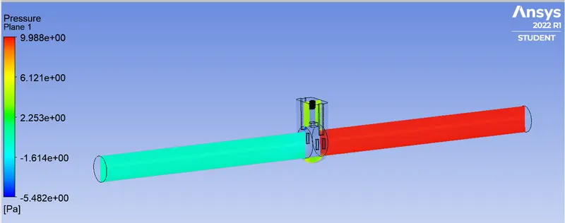
- Pressure contour:
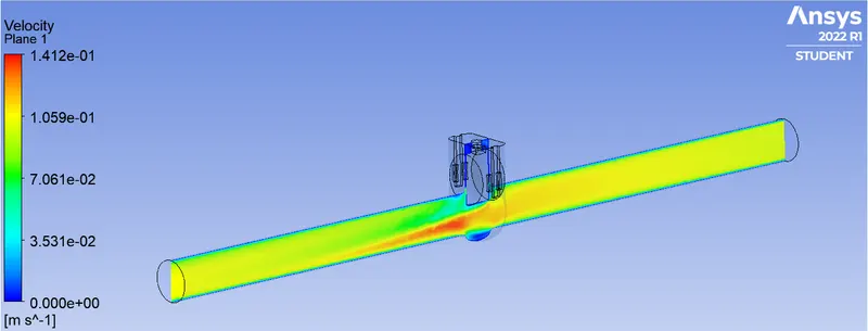
- Velocity Contour:
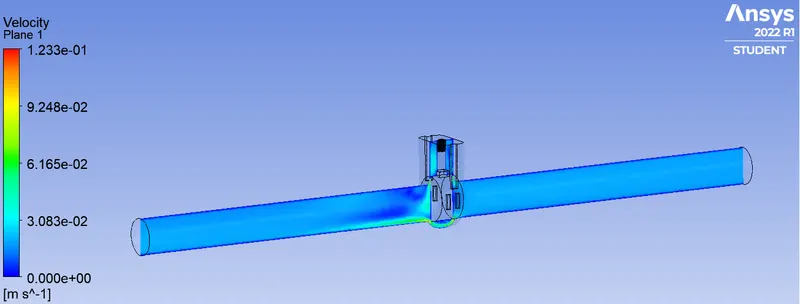
Case 2 = 20 mm:
- Residual Plot:
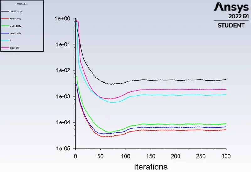
- Mass Flow Rate at outlet:
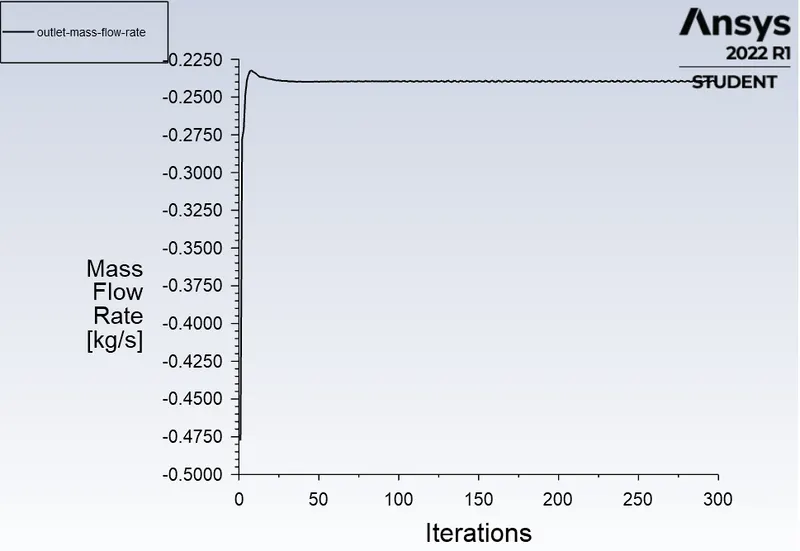

- Flow Coefficient and Flow Factor Calculation:
Flow coefficient:
Pressure Drop = Total pressure at inlet - Total pressure at outlet.
Therefore, △P">△P△P = 10 - 0 = 10 Pa
We need the pressure in terms of psi, conversion form Pascal to psi is 1Pa = 0.000145038 psi
So, 10 Pa = 0.00145038 psi.
Q = 0.2391 kg/s
Q is expressed in Gallons per minute (GPM).
Q in GPM = 5.13 GPM
Specific Gravity of water = 1
Therefore,
`C_v=Q*sqrt(SG)/(DeltaP`
Substituting the value,
`C_v` = 134.7027
Flow factor:
`K_v` = 0.865*`C_v`
`K_v`= 116.5178
- Pressure Contour:
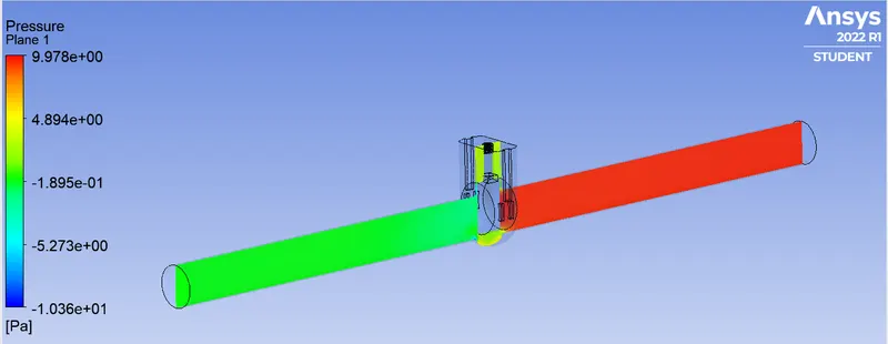
- Velocity Contour:
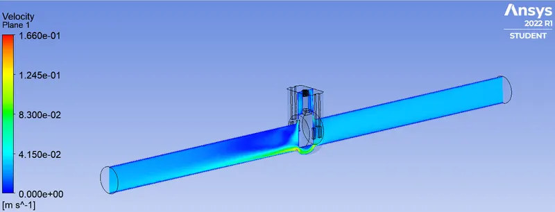
Case 3: 30 mm
- Residual Plot:
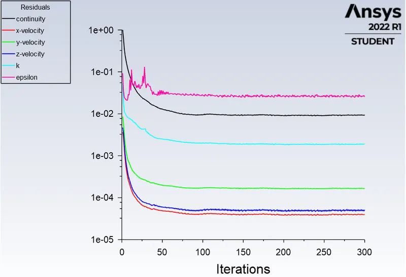
- Mass Flow Rate at outlet:
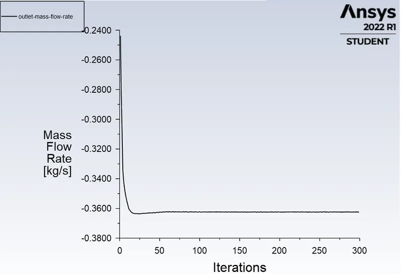

- Flow Coefficient and Flow Factor Calculation:
Flow coefficient:
Pressure Drop = Total pressure at inlet - Total pressure at outlet.
Therefore, △P">△P△P = 10 - 0 = 10 Pa
We need the pressure in terms of psi, conversion form Pascal to psi is 1Pa = 0.000145038 psi
So, 10 Pa = 0.00145038 psi.
Q = 0.3621 kg/s
Q is expressed in Gallons per minute (GPM).
Q in GPM = 7.76 GPM
Specific Gravity of water = 1
Therefore,
`C_v=Q*sqrt(SG)/(DeltaP`
Substituting the value,
`C_v` = 203.7608
Flow factor:
`K_v` = 0.865*`C_v`
`K_v`= 176.253
- Pressure Contour:
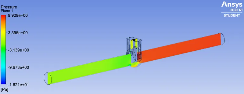
- Velocity Contour:
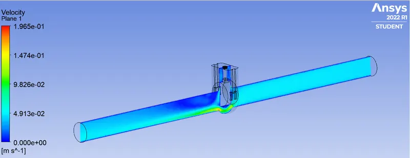
Case 4: 40 mm
- Residual Plot:
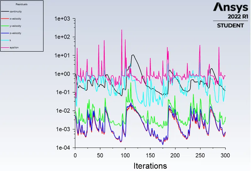
- Mass Flow Rate at outlet:
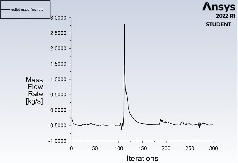

- Flow Coefficient and Flow Factor Calculation:
Flow coefficient:
Pressure Drop = Total pressure at inlet - Total pressure at outlet.
Therefore, △P">△P△P = 10 - 0 = 10 Pa
We need the pressure in terms of psi, conversion form Pascal to psi is 1Pa = 0.000145038 psi
So, 10 Pa = 0.00145038 psi.
Q = 0.4726 kg/s
Q is expressed in Gallons per minute (GPM).
Q in GPM = 10.13 GPM
Specific Gravity of water = 1
Therefore,
`C_v=Q*sqrt(SG)/(DeltaP`
Substituting the value,
`C_v` = 266.0268
Flow factor:
`K_v` = 0.865*`C_v`
`K_v`= 230.1131
- Pressure Contour:
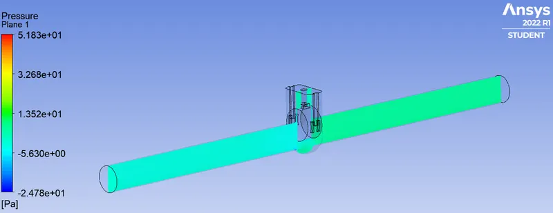
- Velocity Contour:
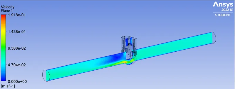
Case 5 : 50 mm
- Residual Plot:
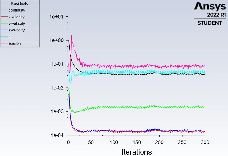
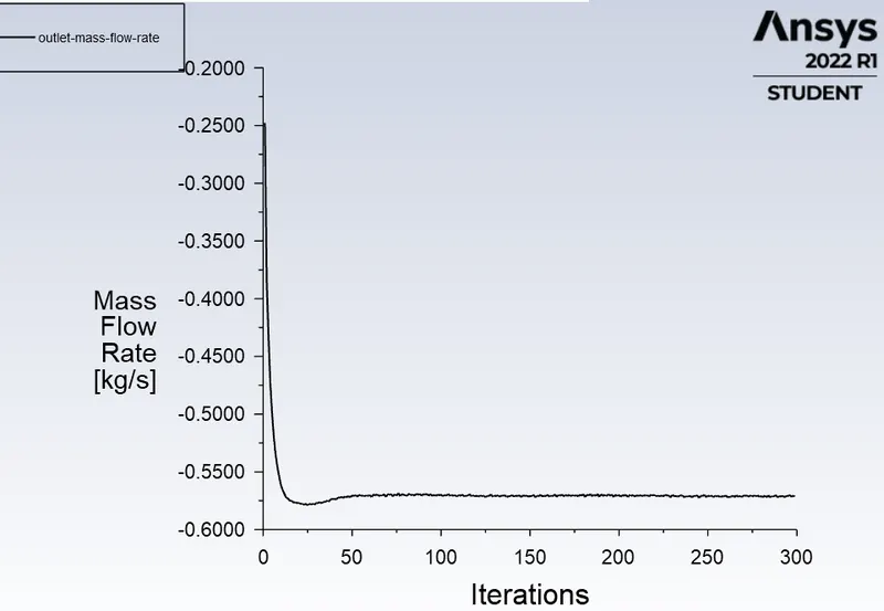
- Mass Flow Rate at outlet:

- Flow Coefficient and Flow Factor Calculation:
Flow coefficient:
Pressure Drop = Total pressure at inlet - Total pressure at outlet.
Therefore, △P">△P△P = 10 - 0 = 10 Pa
We need the pressure in terms of psi, conversion form Pascal to psi is 1Pa = 0.000145038 psi
So, 10 Pa = 0.00145038 psi.
Q = 0.5698 kg/s
Q is expressed in Gallons per minute (GPM).
Q in GPM = 12.22 GPM
Specific Gravity of water = 1
Therefore,
`C_v=Q*sqrt(SG)/(DeltaP`
Substituting the value,
`C_v` = 320.8708
Flow factor:
`K_v` = 0.865*`C_v`
`K_v`= 277.5532
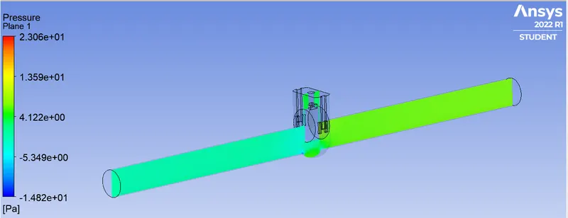
- Pressure Contour:
- Velocity Contour:
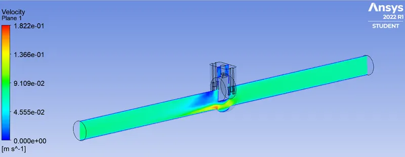
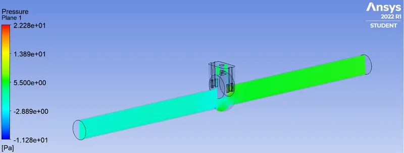
Case 6: 60 mm
- Residual Plot:
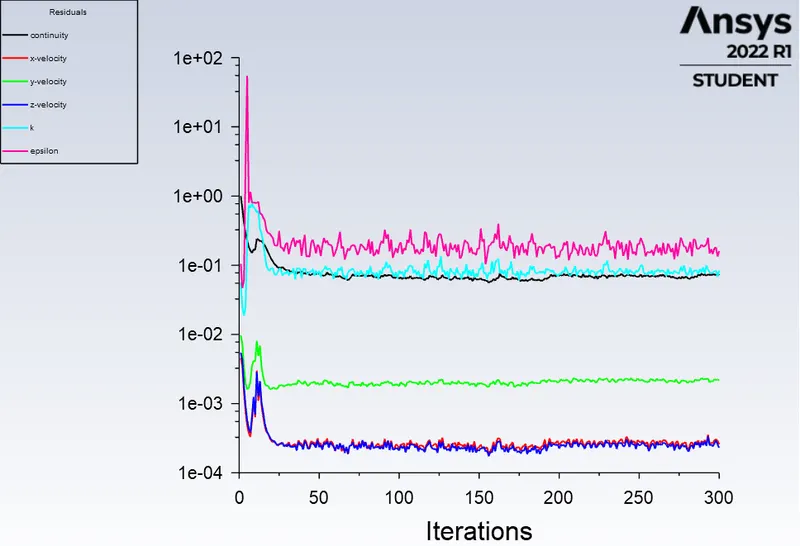
- Mass Flow Rate at outlet:
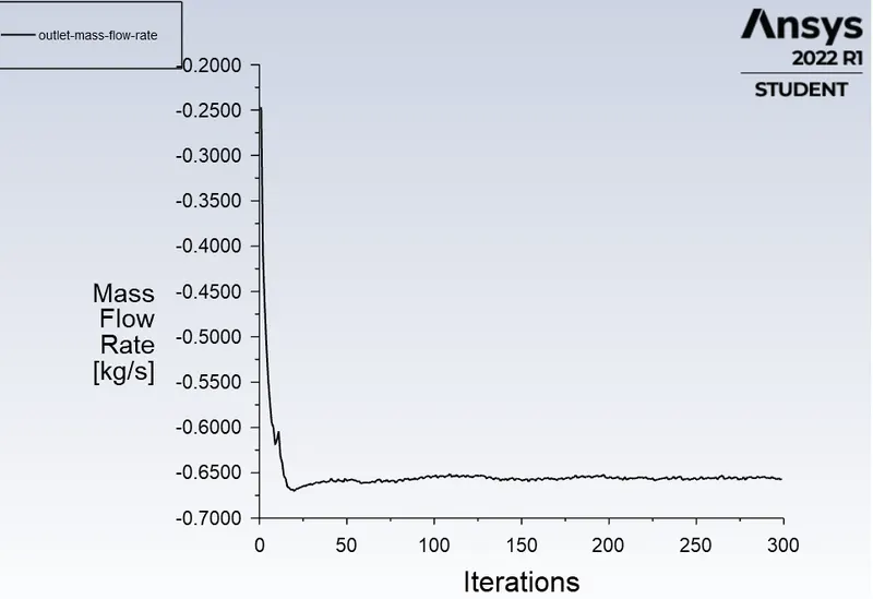

- Flow Coefficient and Flow Factor Calculation:
Flow coefficient:
Pressure Drop = Total pressure at inlet - Total pressure at outlet.
Therefore, △P">△P△P = 10 - 0 = 10 Pa
We need the pressure in terms of psi, conversion form Pascal to psi is 1Pa = 0.000145038 psi
So, 10 Pa = 0.00145038 psi.
Q = 0.6579 kg/s
Q is expressed in Gallons per minute (GPM).
Q in GPM = 14.10 GPM
Specific Gravity of water = 1
Therefore,
`C_v=Q*sqrt(SG)/(DeltaP`
Substituting the value,
`C_v` = 367.8724
Flow factor:
`K_v`= 0.865*`C_v`
`K_v`= 315.6146
- Pressure Contour:
- Velocity Contour:
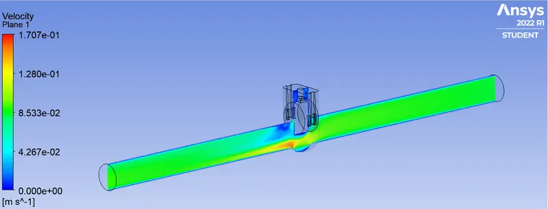
Case 7: 70 mm
- Residual Plot:
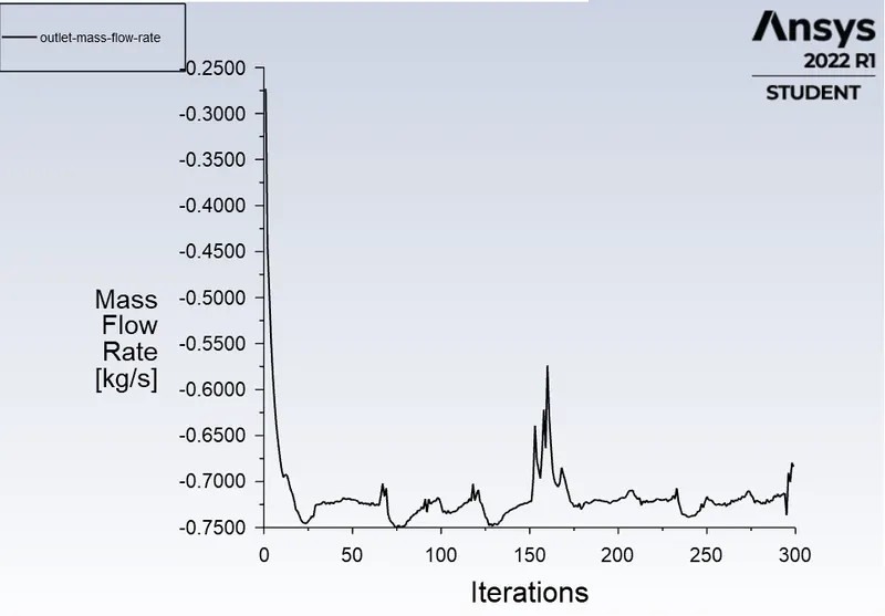
- Mass Flow Rate at outlet:

- Flow Coefficient and Flow Factor Calculation:
Flow coefficient:
Pressure Drop = Total pressure at inlet - Total pressure at outlet.
Therefore, △P">△P△P = 10 - 0 = 10 Pa
We need the pressure in terms of psi, conversion form Pascal to psi is 1Pa = 0.000145038 psi
So, 10 Pa = 0.00145038 psi.
Q = 0.6947 kg/s
Q is expressed in Gallons per minute (GPM).
Q in GPM = 14.89 GPM
Specific Gravity of water = 1
Therefore,
`C_v=Q*sqrt(SG)/(DeltaP`
Substituting the value,
`C_v` = 390.9793
Flow factor:
`K_v` = 0.865*`C_v`
`K_v` = 338.1970
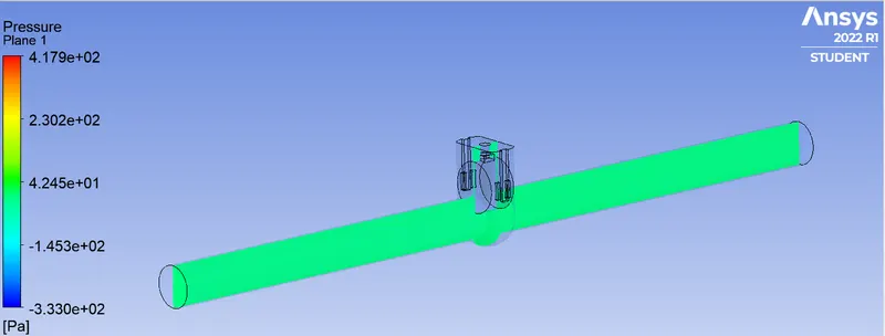
- Pressure Contour:
- Velocity Contour:
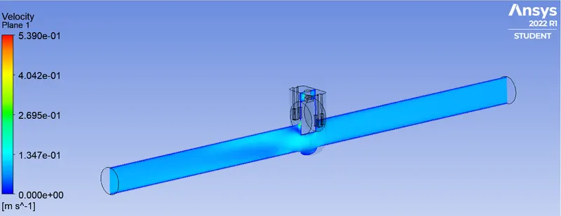
Case 8: 80 mm
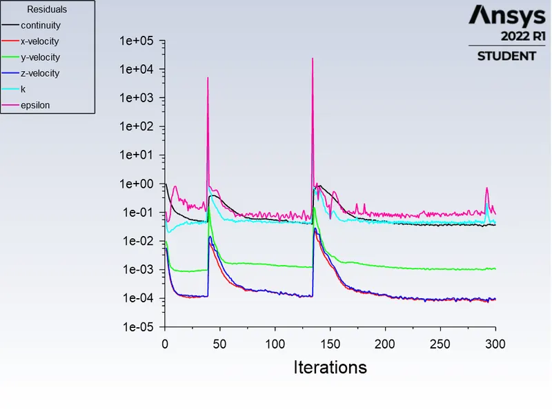
- Residual Plot:
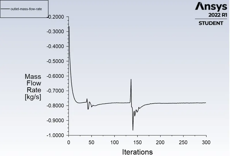
- Mass Flow Rate at outlet:

Flow coefficient:
Pressure Drop = Total pressure at inlet - Total pressure at outlet.
Therefore, △P">△P△P = 10 - 0 = 10 Pa
We need the pressure in terms of psi, conversion form Pascal to psi is 1Pa = 0.000145038 psi
So, 10 Pa = 0.00145038 psi.
Q = 0.7811 kg/s
Q is expressed in Gallons per minute (GPM).
Q in GPM = 16.75 GPM
Specific Gravity of water = 1
Therefore,
`C_v=Q*sqrt(SG)/(DeltaP`
Substituting the value,
`C_v` = 439.81
Flow factor:
`K_v` = 0.865*`C_v`
`K_v` = 380.43
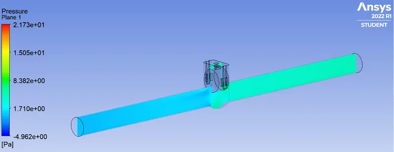
- Pressure Contour:
- Velocity Contour:
Conclusion :
| Disc Lift | Mass Flow Rate | Flow Coefficient | Flow Factor |
| 10 mm | 0.14976 | 84.2987 | 72.9183 |
| 20 mm | 0.23915 | 134.7027 | 116.5178 |
| 30 mm | 0.36216 | 203.7608 | 176.253 |
| 40 mm | 0.47264 | 266.0268 | 230.1131 |
| 50 mm | 0.56986 | 320.8708 | 277.5532 |
| 60 mm | 0.65795 | 367.8724 | 315.6146 |
| 70 mm | 0.69473 | 390.9793 | 338.197 |
| 80 mm | 0.78115 | 439.81 | 380.43 |
- As the disc lift height increases, the value of flow coefficient and flow factor increases.
- The value of pressure below the dics decreases as the resistance to flow decreases.
- A higher value of Flow coefficient indicates lower resistance to the flow and lower Flow coefficient indicates higher resistancce to flow.
- Flow coefficient and pressure drop are essential parameters for designing the valve and could be a great justification for the material selection of the valve.
- The mass flow rate of water increases with increase in disc lift height, as more water can flow through the gap and there is less resistance.