Week -2
1.Making a simulink model of a doorbell using a solenoid block :
Door bell model -
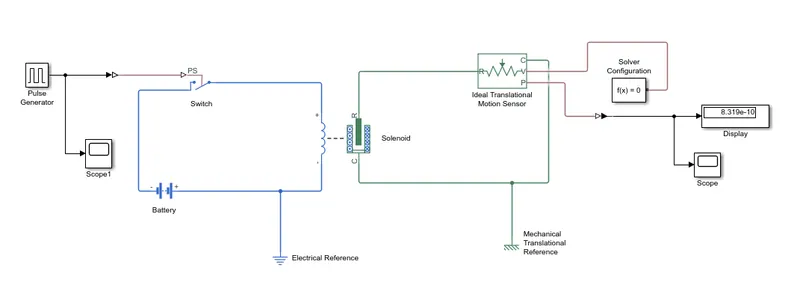
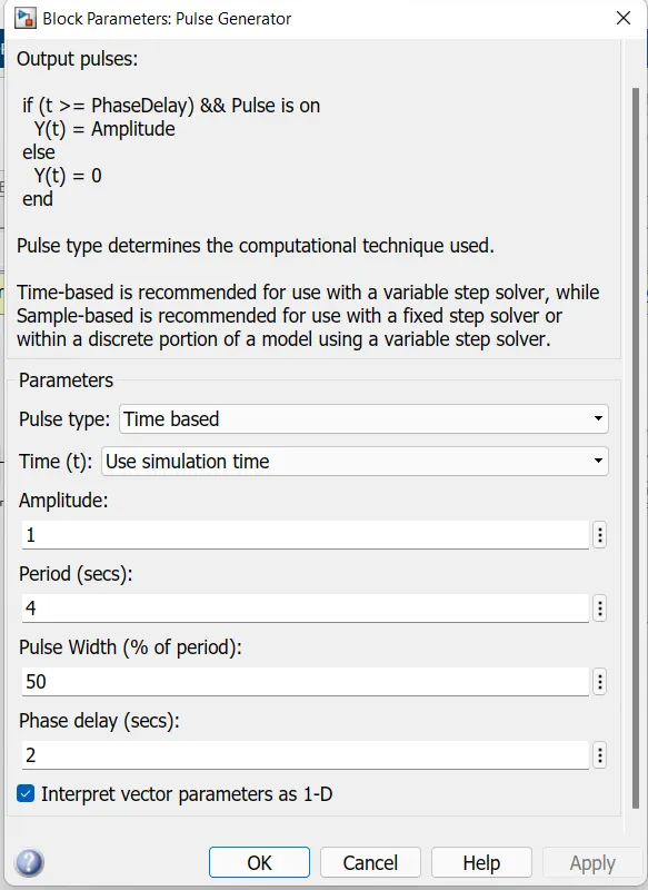
1. Pulse generator - The pulse generator is used to create square wave pulses at regular time intervals.The block waveform parameters Amplitudde,pulse width,period and
phase delay,determining the shpe of the output waveform.
2.Switch - The switch block used is controlled by the external physical signal. If the external signal is greater than the threshhold parameters then the
switch is closed,otherwise switch is open.
3.Battery - The battery block is used in the door bell model for electrical energy transmission. One end of the battery is connected to switch and anothetr end is connected to solenoid.
4.Solenoid - The solenoid block is connected with the switch and battery and we will get a complete electrical circuit.Another end of solenoid is connected to ideal translational
motion sensor and lower end of the solenoid is connected to c port of the ideal translational motion sensor.
5.Electrical reference - Electrical reference is used due to the formation of electrical circuit .
6.Ideal translational motion sensor -Ideal translational motion sensor is connected to solenoid for sensing the signals from the solenoid.A mechanical circuit is formed.
7.Mechanical translational reference -A mechanical translational reference is used due to the formation of mechanical circuit.
8.PS-Simulink convertor is used for converting the signals.
9.Solver configuration -A solver configuration is used for getting the equation of the model.
10.Scope -A scope displays the plot of the model after running the model.
11.Display - A display block shows the output value of the model.
PLOT OF PULSE GENERATOR :
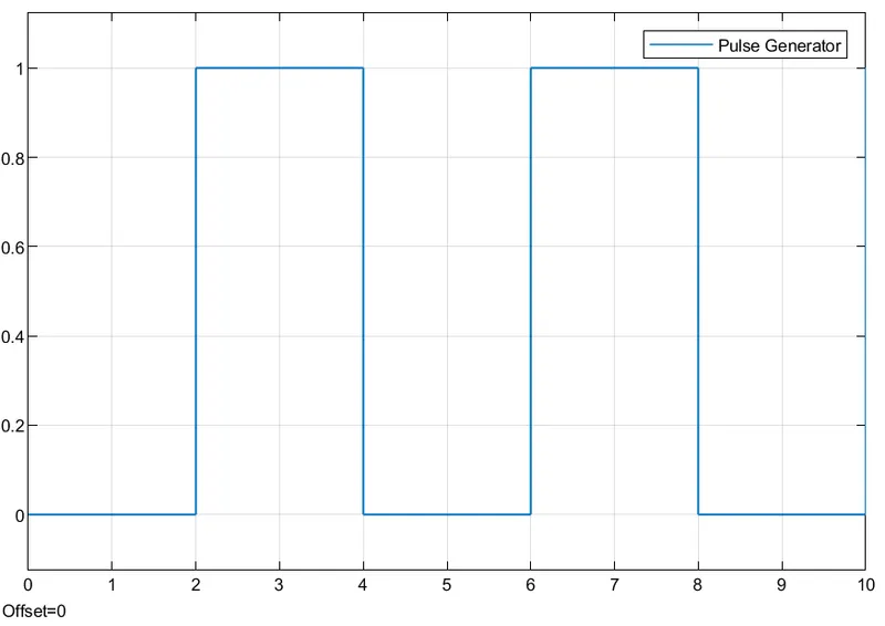
Time period given is 2 seconds to the pulse generator to open and close the switch.When the switch is closed the solenoid block receives electrical power from the battery
and plunger moves from port R to C to hit the bell and produces sound. This plot shows in the scope one which is connected to pulse generator.
PLOT OF PS_SIMULINK CONVERTER :
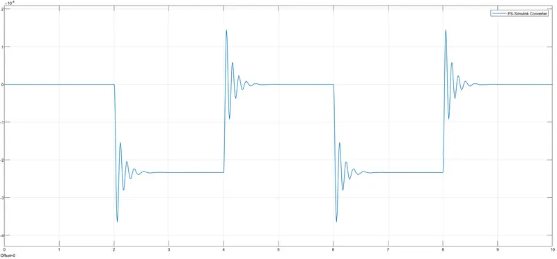
The scope 2 shows above plot of the PS-simulink converter .The scope 2 is connected to the display terminal.
2.Use a thermistor to sensor the temperature of a heater and turn on or turn off the fan as per the below conditions :
Temperature Source : 20 degeree celsius from 0 to 10 seconds,27 degree celsius from 10 to 30 seconds,23 degree celsius from 30 to 50 seconds.
Fan conditions : ON if the temperature above 25 degree celsius,OFF otherwise.
THERMISTOR : A thermistor is a semiconductor that has a resistance capacity more than a conducting material and less than a insulatting material.
It's electrical resistance varies with the change in the temperature or thermally sensitive resistor.There are namely two types of thermistors they are
1. Negative Temperature Coefficient (NTC).
2.Positive Temperature Coefficient (PTC).
Thermistor's relation with temperature also depends on the material in which it is made . A NTC thermistor will decrease it's resistance value when temperature increases
Whereas a PTC will increase it's resistance when it's temperature increases.
Thermistors have high sensitivity which can be upto 10 percent change per degree celsius and their typical response time is 0.5 to 5s with an operating range from -50 to -300 degree celsius.
THERMISTOR MODEL :
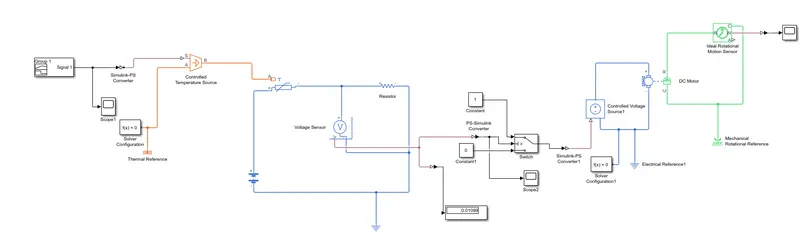
BLOCKS USED :
1. Signal builder : to generate the signal according to the input conditions given.
2.PS-Simulink converter : This block converts the simulink singnals to the respective physical signals.
3. Controlled Temperature Source (CTC) : Provides a temperature physical output based on the condition given to port S.
4.Thermal reference : This block provides the required intial conditions to the connected thermal block of the solver.
5.Thermistor : Uses NTC thermistor relation between temperature and resistance.
6.Battery : It is a storage device that provides the required voltage based on the parameter given.
7.Resistor : Resistor which provides the opposing nature of current in a circuit.
8.Voltage sensor : It is used to measure the voltage or potential difference across any electrical component abnd it should connect in parallel only.
9.Electrical reference :These block provide thr required initial conditions to the connected thermal block solver.
10.Solver configuration : This block specifies the solver parameters that your model needs before you can begin simulation and this is mandatory for all simscape models.
11.PS-Simulink converter : Converts physical signals to the respective simulink signals.
12.Constant : Provides a constant output value.
13.Switch : It has three inputs namely Port 1,Port 2 and Port 3 is a control input where the signal given to Port 2 is satisfied with the condition and threshhold of the switch block
then it passses Port 1 as output and if it is not satisfied then it will pass Port 3 as output.
14.Scope : This block provides the output plot.
15.Controlled voltage source : This block is an ideal voltage source that gives a constant output based on the load requirement connected to it.
16.DC motor : This block represents the electrical and torque characteristics of a DC motor.
17.Ideal Rotational Motion sensor : This block is used to detect whether their is any rotational motion in the DC motor during the simulation.
18. Mechanical Rotational Reference : It given as a reference to the ideal rotational motion sensor.
PLOT IN SIGNAL BUILDER AS A INPUT SIGNAL :
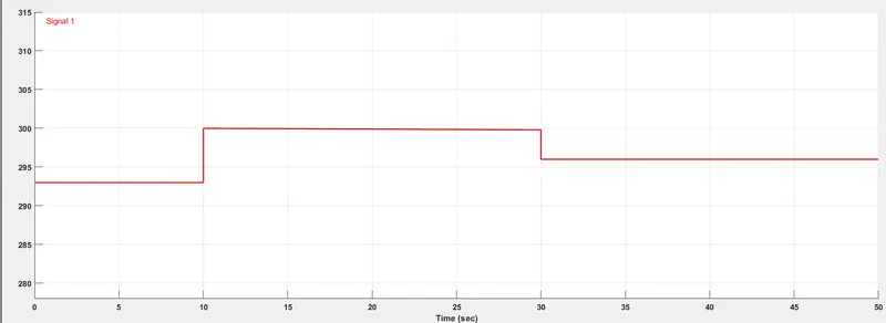
The above plot is the signal builder in which signal are generated according to the given temperature and time.
Then generated signals are given as input to the controlled temperature source.
In the plot time is taken 50 seconds and temperature in 300 kelvin.
from 1 to 10 seconds - 293 k.
from 10 to 30 seconds - 300 k.
from 30 to 50 seconds - 298 k.
INPUT SIGNAL IN SCOPE :
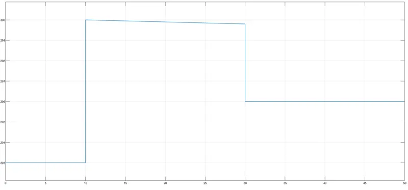
This is the signal plot which shows in the scope which is connected to the signal builder.
OUTPUT SIGNAL OF VOLTAGE VS TIME :
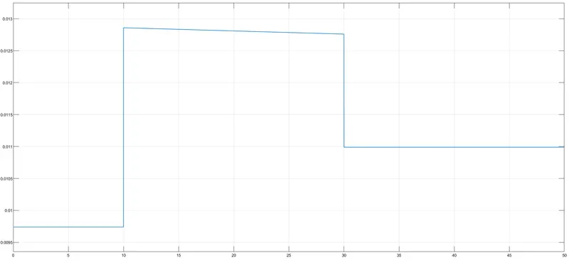
The above plot shows the voltage generated in the voltage sensor .
This plot is shown in the scope which is connected by ps- simulink converter.
And the value of the voltage is displayed in the display block ,which is connected by ps-simulink connverter.
Obtained value is 0.01099.
OUTPUT OF THE IDEAL ROTATIONAL MOTION SENSOR :
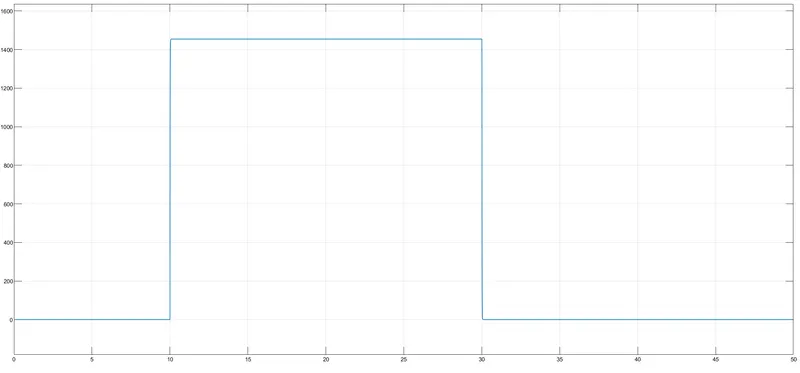
The output of the ideal rotational motion sensor is plotted in the scope.
Their is a change in the plot from 10 to 30 seconds which shows the angular velocity.
The above plot shows the Fan conditions ON when the temperature is above 25degree ,by the motor getting power and rotating.