Week 9 - Parametric study on Gate valve.
Parametric study on Gate valve
Aim: To perform gate valve simulation and parametric study on gate valve.
Objevtive: To perform a parametric study on the gate valve simulation by setting the opening from 10 % to 80%.
- Obtain the mass flow rates at the outlet for each design point.
- Calculate the flow coefficient and flow factor for each opening and plot the graph.
- Discuss the results of the mass flow rate and flow coefficient.
Theory:
Gate valves are devices that are used to shut off the flow of liquids rather than for flow regulation. When fully open, the typical gate valve has no obstruction in the flow path, resulting in very low flow resistance.
Gate valves are mostly used with larger pipe diameter since they are less complex to construct than other types of valves in large sizes. At high pressures, friction can become a problem. As the gate is pushed against its guiding rail by the pressure of the medium, it becomes harder to operate the valve.
Gate valve structure and working, it is actuated by a threaded stem that connects the actuator (handwheel) to the gate.
Flow-Factor(kv):
Kv is the flow coefficient in metric units. It is defined as the flow rate in cubic meters per hour [m3/h] of water at a temperature of 16º celsius with a pressure drop across the valve of 1 bar. Cv is the flow coefficient in imperial units.
`K_v = 0.865 *C_v`
Flow-coefficient(Cv):
The coefficient of flow (Cv) is a formula which is used to determine a valve's flows under various conditions and to select the correct valve for a flow application. The Cv was designed for use with liquid flows, it expresses the flow in gallons per minute of 60º F water with a pressure drop across the valve of 1 psi.
Mathematical formula:
`C_v = Qsqrt((SG)/(grad P))`
Procedure:
Geometry:
Import the model in space claim.
Extract the fluid volume, suppress other parts for physics.
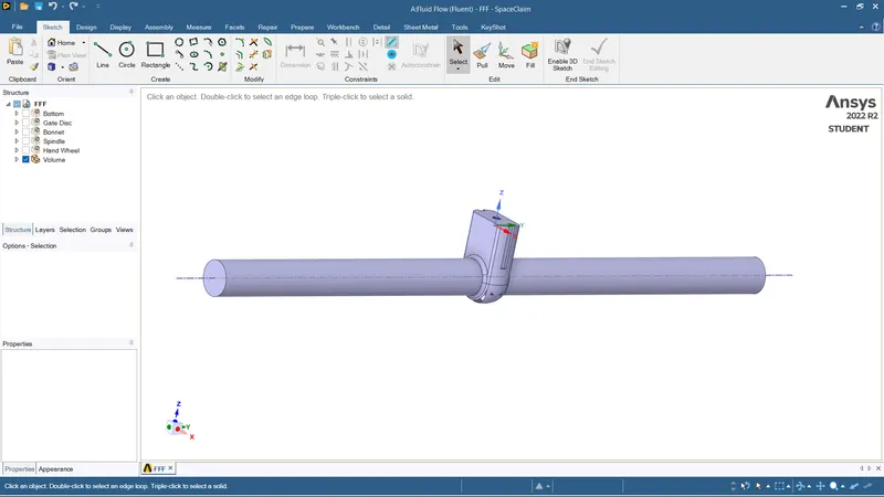
Parameter the gate valve of 10 mm.
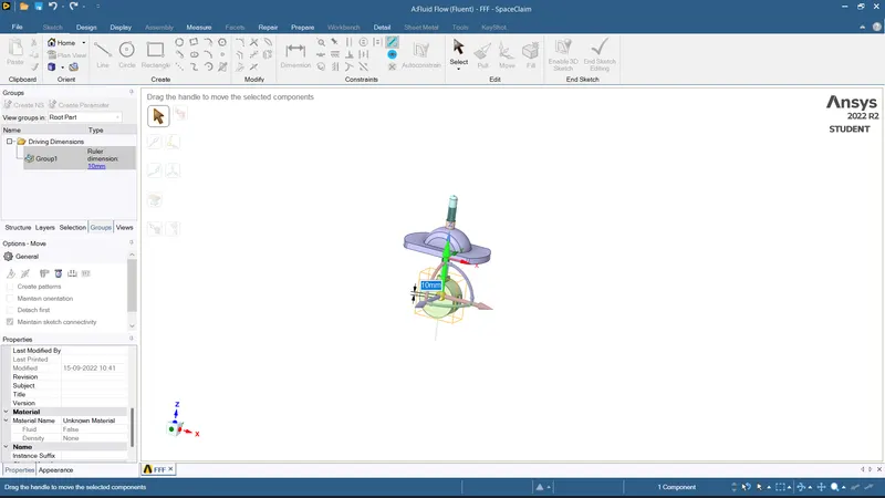
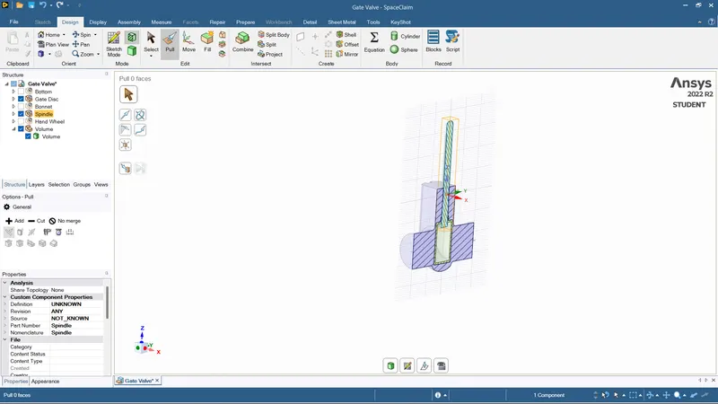
Update the volume context
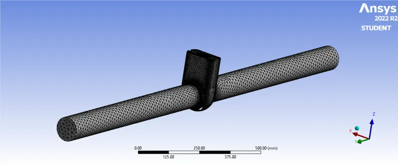
Meshing:
Length = 10 mm
Assign the inlet and outlet conditions.
Setup:
Viscous model - Realizable K-epsilon
Inlet - Pressure inlet
Standard initialization from inlet.
Set the outlet mass flow rate as Output parameter.
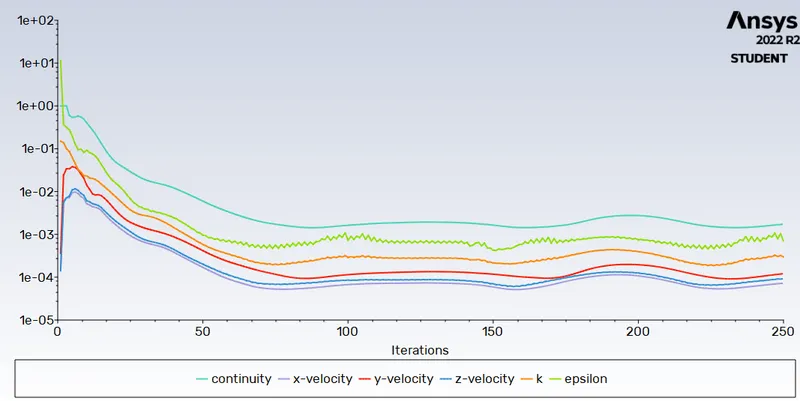
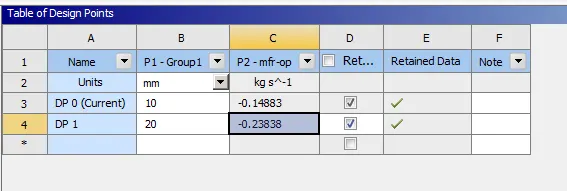
mass floe rate outlet = -0.14883755
Create the parametric list for increment of 10 mm
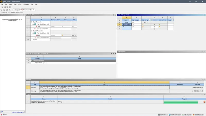
Update all design points
for 30 mm
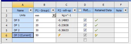
Mass flow rate = 0.36633
Likewise for lift upto = 80 mm
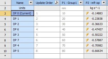
| Lift | Outlet pressure | mass flow rate | Pressure drop | Flow - coeffecient |
| 10 | 0.00177 | 0.14883 | 9.9983 | 0.047 |
| 20 | 0.00355 | 0.23838 | 9.9965 | 0.0753 |
| 30 |
0.004108 |
0.36656 | 9.991 | 0.1299 |
| 40 |
0.009782 |
0.47457 | 9.9901 | 0.1505 |
| 50 |
0.10395 |
0.5022 | 9.8961 | 0.1589 |
| 60 |
0.30524 |
0.57887 | 9.6948 | 0.1858 |
| 70 |
0.6306 |
0.70982 | 9.3694 | 0.2318 |
| 80 |
0.9843 |
0.66634 | 9.0157 | 0.2218 |
(Due to student version of Ansys some error showed up at 70 mm )
Concusion:
As lift of the gate valve is increased, increase in mass flow rate of fluid is observed and decrease in the level of pressure drop also increase in flow- coeffecient.
Parametric study helps a lot to reduce the solving time in studying the effect of change of parameters on the system.