Week 9 - Parametric study on Gate valve.
Aim: To make use of parametric option in order to study the effciency of gate valve by setting up simulation.
What isparametric study?
A parametric analysis is the study of the influence of different geometric or physical parameters or both on the solution of the problem.All you have to do is to set a list of alternative values to each input parameter. When you view the result of any output, it displays a table or graph of how it varies for each combinations of the input parameters.
Gate Valve:
Gate valve controls the media's flow by lifting the gate (open) and lowering the gate (closed). A gate valve's distinct feature is the straight-through unobstructed passageway, which induces minimal pressure loss over the valve. A gate valve's main components are body, seat, gate, stem, bonnet, and actuator. The primary operation mechanism is straightforward. Turning the handwheel rotates the stem, which moves the gate up or down via the threads. They require more than one 360° turn to fully open/close the valve. Lifting the gate from the path of the flow, the valve opens. Lowering the gate to its closed position seals the bore resulting in a full closure of the valve.
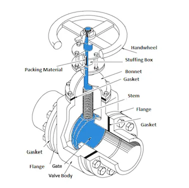
Methodology: We have been provided with geometry of gate valve, which will be prepared for the simuation, using the set parameter option we are going to vary the input parameter lift of the gate body. With varying lift we will get two main output i.e the mass flow rate at outlet and pressure at the outlet, to calculate the flow coeffcient and flow factor.
Geometry:
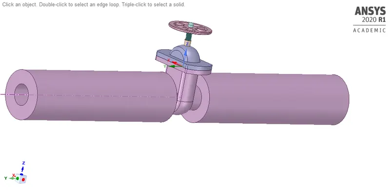
The geometry is prepared using spaceclaim, where the gate disc is given a lift using move option and the volume under consideration is extracted for our analysis. the inlet and outlet are extended at about 800mm in order to visualize the flow more properly.
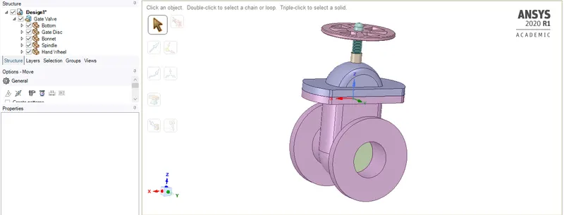
Prepared geometry:
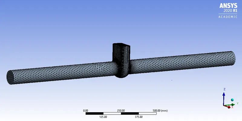
Meshing:
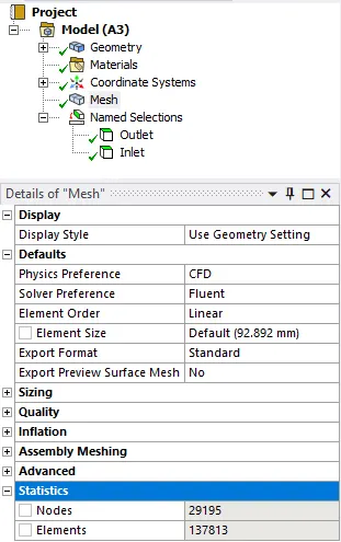
The meshing of geometry is set to default mesh size.
Solution setup:
Model:
k-epsilon realizable(good for moderately complex behaviour like pipe flow) with scalable wall function.
Material:
water-liquid
Boundary condition:
Inlet-pressure inlet (10 pascal)
Outlet-pressure outlet
Report defination:
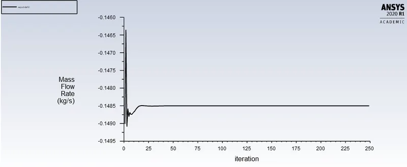
mass flow rate at outlet
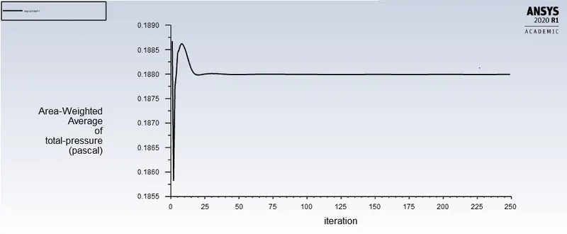
pressure(total) at outlet
Contour:
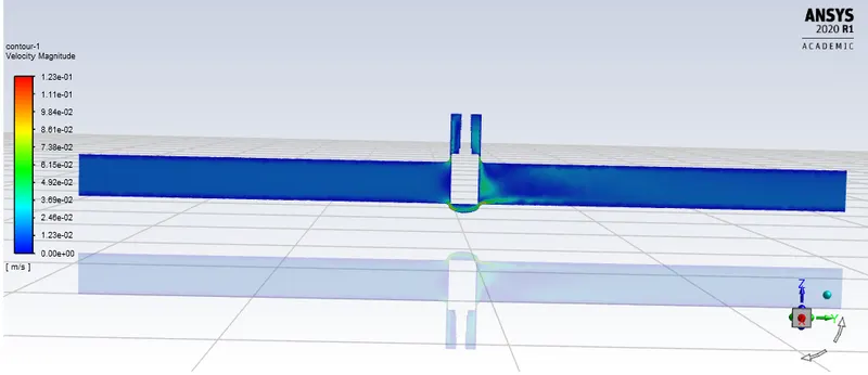
Velocity contour at plane 3
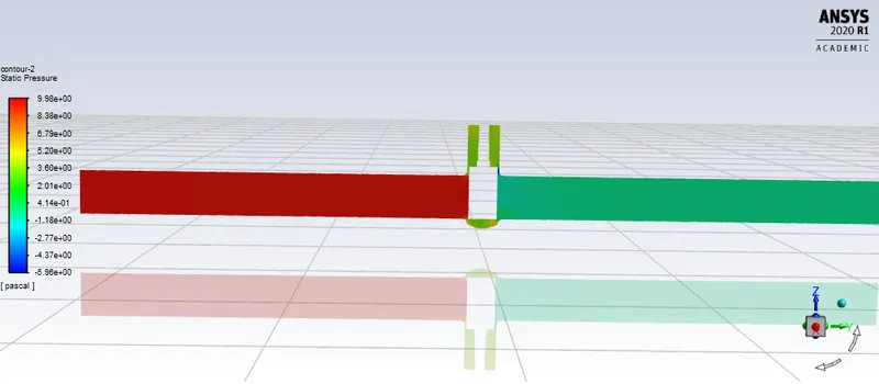
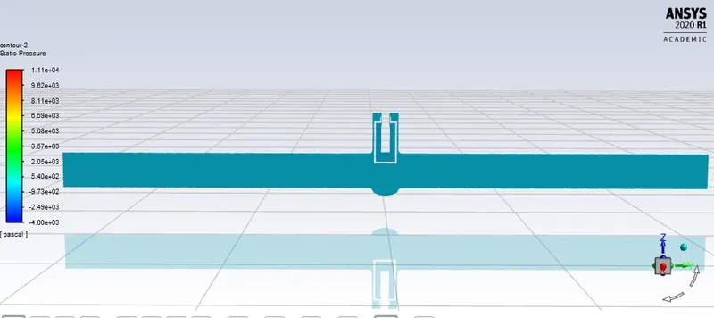
Pressure contour at plane 3
Initialization:
Standard initialization-inlet
Calculation:
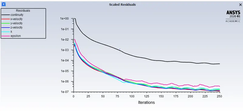
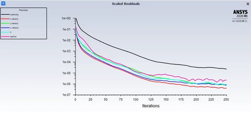
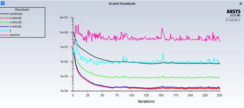
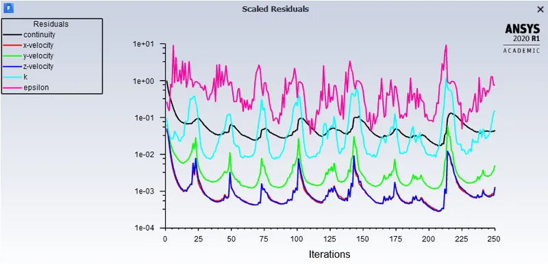
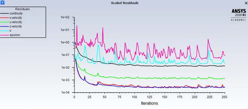
The simulation is performed for 250 iterations
Case1) 10 mm lift of gate disc
Residual plot:
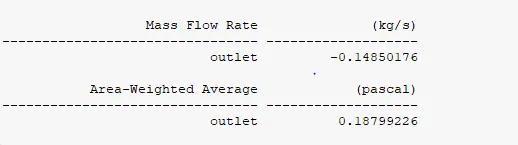
Mass flow rate at outlet:
Total pressure at outlet:
Velocity contour plot:
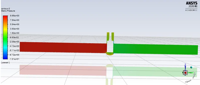
Pressure contour plot:
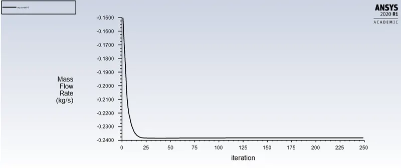
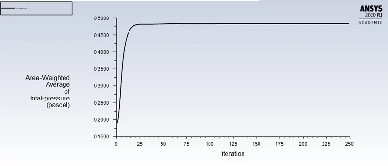
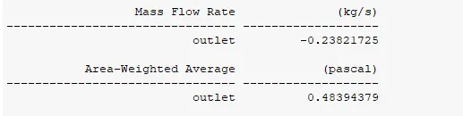
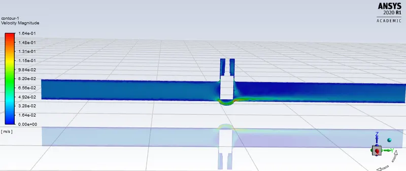
Case 2) 20 mm lift of gate disc
Residual plot:
Mass flow rate at outlet:
Total pressure at outlet:
Velocity contour plot:
Pressure contour plot:
Case 3) 35 mm lift of gate disc
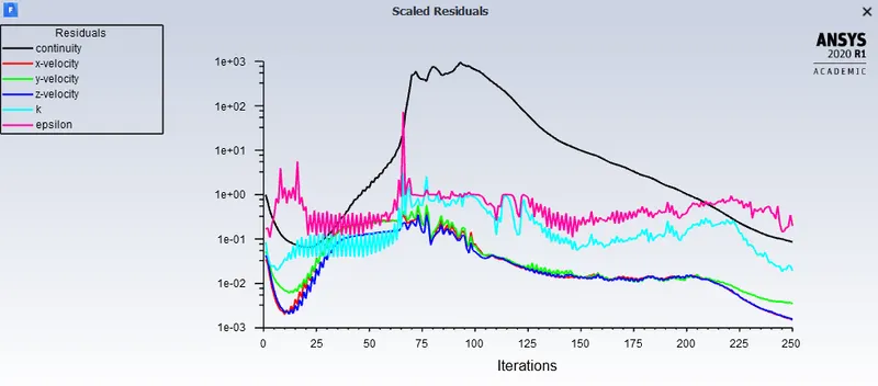
Residual plot:
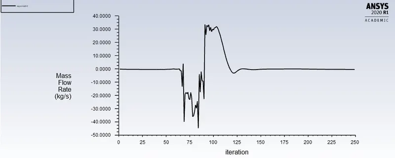
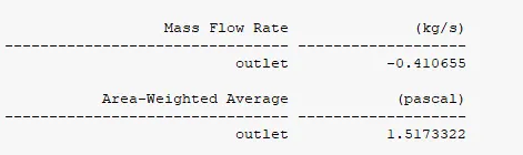
Mass flow rate at outlet:
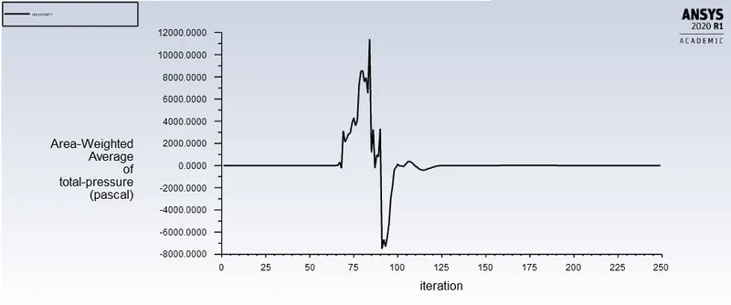
pressure at outlet:
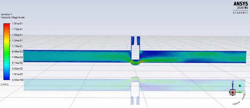
Velocity contour plot:
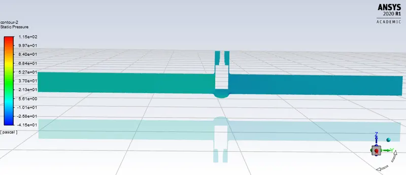
Pressure contour plot:
Case 4) 40 mm lift of gate disc
Residual:
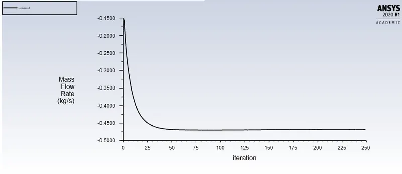
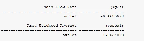
Mass flow rate at outlet:
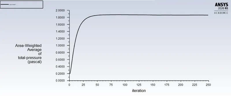
pressure at outlet:
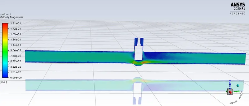
Velocity contour plot:
 Pressure contour plot:
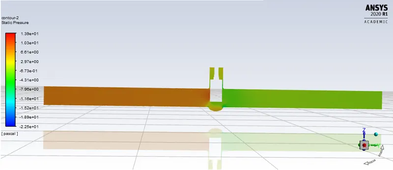
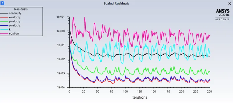
Case 5) 50 mm lift of gate disc
Residual:
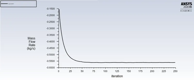
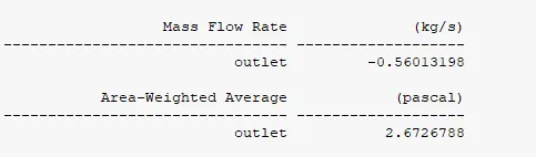
Mass flow rate at outlet:
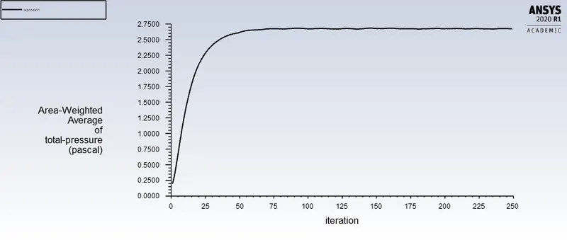
Pressure at outlet:
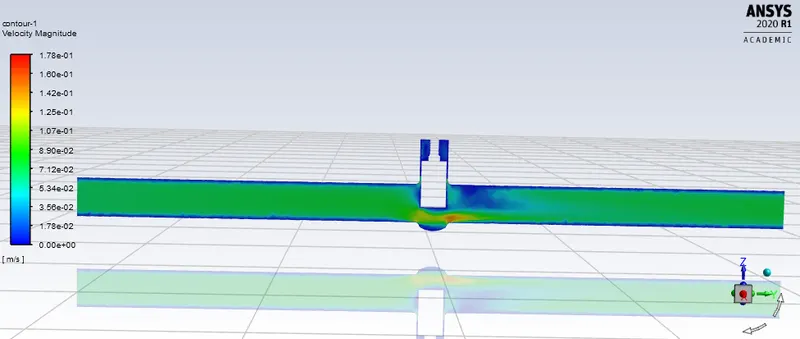
Velocity contour plot:
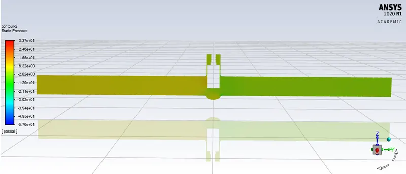
Pressure contour plot:
Case 6) 65 mm lift of gate disc
Residual:
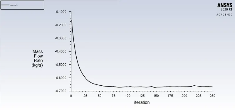
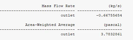
Mass flow rate at outlet:
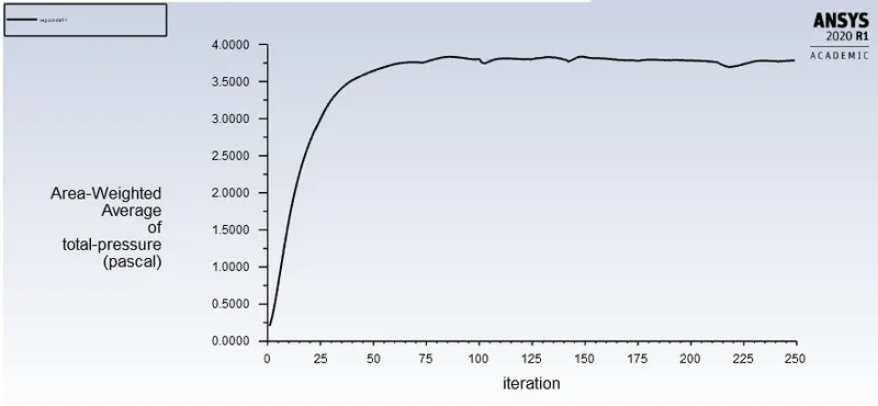
Pressure at outlet:
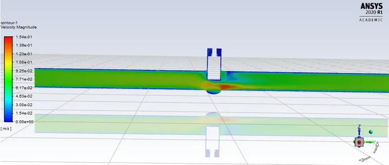
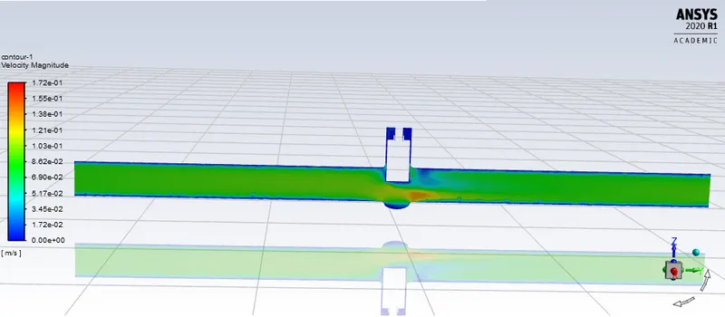
Velocity contour plot:
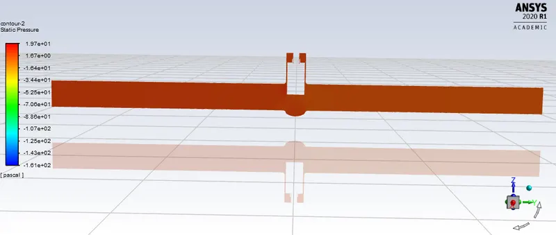
Pressure contour plot:
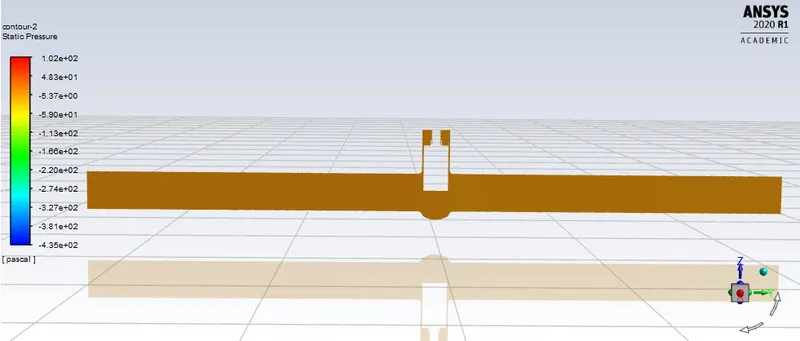
Case 7) 70 mm lift of gate disc
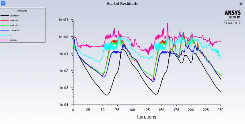
Residual:
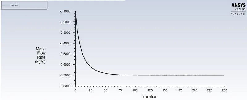
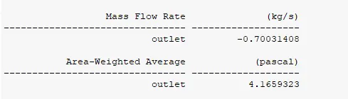
Mass flow rate at outlet:
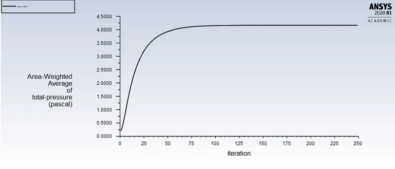
Pressure at outlet:
Velocity contour plot:
Pressure contour plot:
Case 8) 81 mm lift of gate disc
Residual:
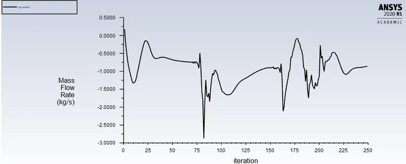
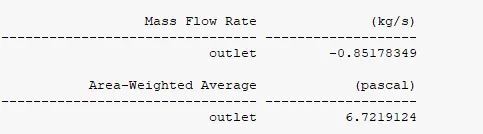
Mass flow rate at outlet:
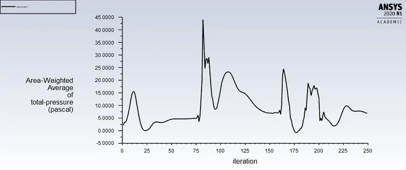
Pressure at outlet:
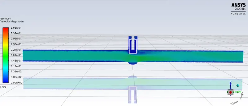
Velocity contour plot:
Pressure contour plot:
Flow coeffcient:
It describes the relationship between the pressure drop across an orifice valve or other assembly and the corresponding flow rate.
Mathematically the flow coefficient Cv is expressed as :
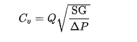
where:
- Q is the rate of flow (expressed in US gallons per minute),
- SG is the specific gravity of the fluid (for water = 1),
- ΔP is the pressure drop across the valve (expressed in psi).
Flow factor:
The metric equivalent flow factor (Kv; commonly used everywhere else in the world with the exception of the United States) is calculated using metric units :
where
- Kv is the flow factor (expressed in {\displaystyle [m^{3}.h^{-1}]}
 ).
). - Q is the flowrate (expressed in cubic metres per hour [{\displaystyle m^{3}/h}
 ]),
]), - SG is the specific gravity of the fluid (for water = 1),
- ∆P is the differential pressure across the device (expressed in [bar]).
Kv can be calculated from Cv using the equation:

Result:
| Lift of gate disc | Mass flow rate kg/s | Inlet pressure (pascal) | outlet pressure (pascal) | pressure drop | Flow coeffcient Cv | Flow factor Kv |
| 10 | 0.1485 | 10 | 0.1879 | 9.8121 | 0.0474 | 0.041 |
| 20 | 0.2382 | 10 | 0.4839 | 9.5161 | 0.07721 | 0.06679 |
| 30 | 0.4106 | 10 | 1.5173 | 8.4827 | 0.14097 | 0.1219 |
| 40 | 0.4685 | 10 | 1.8624 | 8.1376 | 0.16422 | 0.142 |
| 50 | 0.5601 | 10 | 2.6726 | 7.3274 | 0.20685 | 0.17893 |
| 60 | 0.6675 | 10 | 3.7832 | 6.2168 | 0.274 | 0.237 |
| 70 | 0.7003 | 10 | 4.165 | 5.835 | 0.2899 | 0.2507 |
| 80 | 0.8517 | 10 | 6.7219 | 3.2781 | 0.4006 | 0.346 |
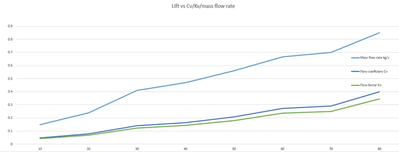
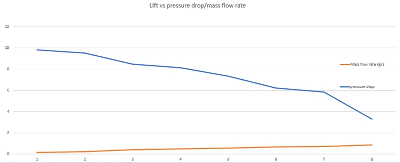
Graph:
Conclusion:
1) The flow rate is increased when pressure drop is reducing in pipe,this is beacuse the as lift increases more amount of fluid flows without obstruction which produces high pressure region at outlet, reducing the presure drop.
2) The velocity increases as the lift of the disc is increased, which reduces onstruction to the flow.
3) The flow factor, flow coefficient and mass flow rate gradually increases with increase in lift along with decreasing preddure drop.